Table of Contents
Advertisement
Quick Links
Important
Please read this User's Manual, and Setup Manual (separate volume)
carefully to familiarize yourself with safe and effective usage.
• Please refer to the Setup Manual for basic information ranging from
connection of the monitor to a PC to using the monitor.
• The latest User's Manual is available for download from our web site:
http://www.radiforce.com
Advertisement
Table of Contents

Related Manuals for Eizo RadiForce RX840


Summary of Contents for Eizo RadiForce RX840
-
Page 1: Cover
Important Please read this User’s Manual, and Setup Manual (separate volume) carefully to familiarize yourself with safe and effective usage. • Please refer to the Setup Manual for basic information ranging from connection of the monitor to a PC to using the monitor. •... - Page 2 EIZO NANAO CORPORATION. EIZO NANAO CORPORATION is under no obligation to hold any submitted material or information confidential unless prior arrangements are made pursuant to EIZO NANAO CORPORATION’s receipt of said information.
-
Page 3: Notice For This Monitor
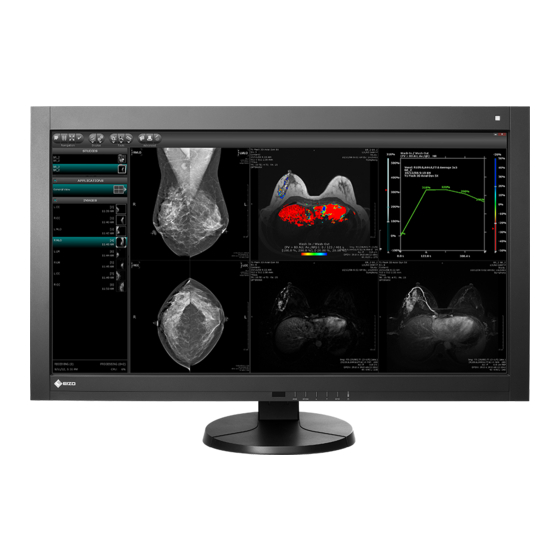
Notice for this monitor This product is suited to display medical images of such modalities as MRI, CT, and PET. It does not support the display of mammography images for diagnosis. This product has been adjusted specifically for use in the region to which it was originally shipped. If the product is used outside the region, it may not operate as specified in the specifications. -
Page 4: Cleaning
Cleaning Attention • Chemicals such as alcohol and antiseptic solution may cause gloss variation, tarnishing, and fading of the cabinet or panel, and also quality deterioration of the image. • Never use any solvents or chemicals, such as thinner, benzene, wax, alcohol, and abrasive cleaner, which may damage the cabinet or panel. -
Page 5: Table Of Contents
4-2. Checking Grayscale ........23 1-1. Features ............7 ● ExecutingGrayscaleCheck ......23 ● 1-2. EIZO LCD Utility Disk........8 ViewingGrayscaleCheckresult....23 ● Diskcontentsandsoftwareoverview..... 8 4-3. Setting On/Off for Warning and QC ● TouseRadiCSLE/ScreenManagerPro History ............23 forMedical... - Page 6 China Measures for RoHS Compliance in ChinaRoHS ............55 CONTENTS...
-
Page 7: Chapter 1 Introduction
Chapter 1 Introduction Thank you very much for choosing an EIZO color LCD monitor. 1-1. Features • 36.4 inches • Applicable to the resolution of 8M pixels (4096 × 2160 dots) • Uses high-contrast panel (1000:1). Enables the display of sharp images. -
Page 8: Eizo Lcd Utility Disk
1-2. EIZO LCD Utility Disk An “EIZO LCD Utility Disk” (CD-ROM) is supplied with this product. The following table shows the disk contents and the overview of the software programs. ● Disk contents and software overview The disk includes application software programs for adjustment, and User’s Manual. Refer to Readme.txt file on the disk for software startup procedures or file access procedures. -
Page 9: Basic Operations And Functions
1-3. Basic Operations and Functions ● Basic Adjustment menu operations Displaying Adjustment Menu 1. Press . The Adjustment menu appears. Menutitle Currentmode Item Settings Menu Adjusting/Setting 1. Choose a menu to adjust/set with , , and then press 2. Choose an item to adjust/set with , , and then press 3. -
Page 10: Functions
● Functions The following table shows all the Adjustment menu’s adjustment and setting menus. Main menu Item Reference Color “2-4.AdjustingColor”(page13) Brightness Contrast Temperature Gamma Advanced Settings Saturation Gain HybridArea HybridAssignment HighlightArea “3-7.ReturnToDefaultSetting”(page21) ColorReset RadiCSSelfQC “4-1.ExecutingCalibration”(page22) SelfCalibration “4-2.CheckingGrayscale”(page23) GrayscaleCheck “4-3.SettingOn/OffforWarningandQC Settings History”(page23) Screen “2-3.SettingtheScreenPosition”(page12) -
Page 11: Chapter 2 Adjusting Screens
Chapter 2 Adjusting Screens 2-1. Compatible Resolutions For details on compatible resolutions, refer to “Compatible Resolutions” in the Setup Manual. 2-2. Setting the Resolution When you connect the monitor to the PC and find that the resolution is improper, or when you want to change the resolution, follow the procedure below. -
Page 12: Setting The Screen Position
Windows XP 1. Right-click the mouse anywhere on the desktop except for icons. 2. From the displayed menu, click “Properties”. 3. When the “Display Properties” dialog box is displayed, click the “Settings” tab and select desired resolution for “Screen resolution” under “Display”. 4. -
Page 13: Adjusting Color
2-4. Adjusting Color ● To select the display mode (CAL Switch mode) This function allows easy selection of a desired mode according to monitor application. Color Mode Mode Purpose 1-DICOM AvailabletodisplayinDICOMmode. 2-Custom Selectoneoftheseusermodestodefineadesiredsetofparametersettings. 3-CAL1 Displaysthescreenadjustedbycalibrationsoftware. 4-CAL2 5-CAL3 6-Hybrid-γ Automaticallyidentifiesthedisplayareaforthemonochromeandcolorimagesonthe samescreen,anddisplayseachsetstatus. 7-sRGB SuitableforcolormatchingwithsRGBcompatibleperipherals. -
Page 14: Adjustable Settings In Each Mode
● Adjustable settings in each mode The adjustable settings depend on the mode. (You cannot select any non-adjustable or non-settable function.) √: Adjustable -: Not adjustable CAL Switch mode 3-CAL1 Icon Function 1-DICOM 2-Custom 4-CAL2 6-Hybrid-γ 7-sRGB 8-Text 5-CAL3 Brightness √... -
Page 15: To Adjust Contrast
● To adjust contrast The luminance of the screen is adjusted by varying the video signal level. Adjustable range 0 to 100% Procedure 1. Choose “Color” from the Adjustment menu, and press 2. Choose “Contrast” from “Color”, and press “Contrast” appears. 3. -
Page 16: To Adjust Gamma
● To adjust gamma Gamma can be adjusted. The brightness of the monitor varies depending on the input signal, however, the variation rate is not proportional to the input signal. To keep the balance between the input signal and the brightness of the monitor is called as “Gamma correction”. -
Page 17: To Adjust Gain
● To adjust gain The brightness of each color component red, green, and blue is called Gain. You can change the hue of “white” by adjusting gain. Adjustable range 0 to 100% Procedure 1. Choose “Color” from the Adjustment menu, and press 2. -
Page 18: To Set The Detection Type In The Monochrome Display Area
● To set the detection type in the monochrome display area You can set the detection type in the monochrome image display area. Procedure 1. Choose “Color” from the Adjustment menu, and press 2. Choose “Hybrid Assignment” from “Color”, and press 3. -
Page 19: Chapter 3 Setting Monitor
Chapter 3 Setting Monitor 3-1. Enabling/Disabling Mode Selection Allows you to select the specified modes only. Use this function when all the display modes are not available or when keeping the display mode unchanged. Procedure 1. Choose “Tools” from the Adjustment menu, and press 2. -
Page 20: Locking Buttons
3-4. Locking Buttons This function allows you to lock the adjusted/set status to prevent changing them. Procedure 1. Press to turn off the monitor. 2. Holding down, press for at least two seconds to turn on the monitor. The “Optional Settings” menu appears. 3. -
Page 21: Enabling/Disabling Dc5V Output
3-6. Enabling/Disabling DC5V Output This function allows you to enable/disable the DC5V output. Normally, turn it off during use. Procedure 1. Press to turn off the monitor. 2. Holding down, press for at least two seconds to turn on the monitor. The “Optional Settings”... -
Page 22: Chapter 4 Controlling Monitor Quality
Chapter 4 Controlling Monitor Quality This product has the built-in Integrated Front Sensor, which allows the user to perform periodic calibration and Grayscale Check for the monitor independently. Note • To perform advanced quality control that conforms to medical standards, use the optional monitor quality control software kit “RadiCS UX1”. -
Page 23: Checking Grayscale
4-2. Checking Grayscale This function allows you to execute Grayscale Check and view the latest result. In addition, when the schedule is set using RadiCS, the next grayscale check schedule appears. ● Executing Grayscale Check Procedure 1. Choose “RadiCS SelfQC” from the Adjustment menu, and press 2. -
Page 24: Chapter 5 Power Saving Functions
Chapter 5 Power Saving Functions 5-1. Setting Power Save This function allows you to set the monitor into the power saving mode according to the PC status. When the monitor has shifted to the power saving mode, the images on the screen are not displayed. Attention •... -
Page 25: Setting The Power Saving Mode When A Person Leaves The Monitor
5-3. Setting the power saving mode when a person leaves the monitor The sensor on the front side of the monitor detects the movement of a person by setting a value from “Level-1” to “Level-4” of the Presence Sensor function. When a person moves away from the monitor, it shifts to the power saving mode automatically and does not display the images on the screen to reduce the power consumption. -
Page 26: Chapter 6 Troubleshooting
Chapter 6 Troubleshooting If a problem still remains after applying the suggested remedies, contact your local dealer. 6-1. No picture Problem Possible cause and remedy 1. No picture • Checkwhetherthepowercordandtheadapterpower • Powerindicatordoesnotlight. cableareconnectedproperly. • TurntheACadaptermainpowerswitchon. • Press . • TurnofftheACadaptermainpower,andthenturniton againafewminuteslater. -
Page 27: Imaging Problems
Problem Possible cause and remedy • Themessageshowsthattheinputsignalisout • CheckwhetherthePCisconfiguredtomeettheresolution ofthespecifiedfrequencyrange.(Suchsignal andverticalscanfrequencyrequirementsofthemonitor frequencyisdisplayedinmagenta.) (see“CompatibleResolutions”intheSetupManual.). Example: • RebootthePC. • Selectanappropriatedisplaymodeusingthegraphics board’sutility.Refertothemanualofthegraphicsboard fordetails. fD: Dotclock fH: Horizontalscanfrequency fV: Verticalscanfrequency 6-2. Imaging problems Problem Possible cause and remedy 1. The screen is too bright or too dark. •... -
Page 28: Other Problems
6-3. Other problems Problem Possible cause and remedy 1. The adjustment menu does not appear. • Checkwhethertheoperationlockfunctionworks(see“3-4. LockingButtons”(page20)). 2. No mode menu is displayed. • Checkwhethertheoperationlockfunctionworks(see“3-4. LockingButtons”(page20)). 3. (When using Presence Sensor) • Checkthesettingenvironmentofthemonitor.Presence The images remain to be displayed when Sensormaynotworkcorrectlyinthefollowing... -
Page 29: Error Code Table
Problem Possible cause and remedy 7. The Hybrid Gamma function cannot be • Checkwhethertheinputresolutionsoftheleftandright used. screensarethesame. • Thisfunctioncanbeusedonlywhentheinputresolutions oftheleftandrightscreensarethesameorthesignals areinputtoeitherscreenonly. 8. SelfCalibration/Grayscale Check failure • Refertotheerrorcodetable. • Ifanerrorcodethatdoesnotappearintheerrorcode tableisdisplayed,contactyourlocaldealer. ● Error Code Table Error Code Details 0*** • ErrorsthatoccurredduringSelfCalibration 1*** •... -
Page 30: Chapter 7 Reference
Chapter 7 Reference 7-1. How to Attach the Arm Another manufacturer’s arm (or another manufacturer’s stand) can be attached by removing the stand section of the monitor. Attention • When attaching an arm or stand, follow the instructions of their User’s Manual. •... -
Page 31: How To Install The Wall Mounting Device
7-2. How to Install the Wall Mounting Device The monitor and AC adapter can be attached to a wall mounting device. Attention • Ask an installation contractor for the attachment. • Prepare a wall mounting device separately. • When installing a wall mounting device, follow the instructions of its User’s Manual. •... -
Page 32: Connecting Multiple Pcs
7-3. Connecting Multiple PCs The product has multiple connections to PCs and allows you to switch to one of the connections for display. Connection examples DisplayPortconnector DVI-Dconnector Digital Digital (DVI) (DisplayPort) Signalcable Signalcable (suppliedPP200) (suppliedDD200-DL) DVIconnector DVIconnector DisplayPortconnector DisplayPortconnector Port1 Port2 Port1 Port2... -
Page 33: To Set Input Signal Selection
● To set input signal selection Setting Function Auto ThemonitorrecognizestheconnectorthroughwhichPCsignalsareinput. WhenaPCisturnedofforentersthepowersavingmode,themonitorautomatically displaysanothersignal. Manual ThemonitordetectsonlythePC’ssignalscurrentlydisplayingautomatically.Selectan activeinputsignalwith“Input”. Procedure 1. Choose “Tools” from the Adjustment menu, and press 2. Choose “Input Selection” from “Tools”, and press 3. Select “Auto” or “Manual” with or . 4. -
Page 34: Making Use Of Usb (Universal Serial Bus)
1. A PC equipped with a USB port or another USB hub connected to a USB compatible PC 2. Windows 2000/XP/Vista/7 or Mac OS 9.2.2 and Mac OS X 10.2 or later 3. EIZO USB cable (MD-C93) Attention • This monitor may not work depending on PC, OS or peripheral devices to be used. For USB compatibility of peripheral devices, contact their manufactures. -
Page 35: Displaying Monitor Information
7-5. Displaying Monitor Information ● Displaying the signal information This function displays the information about the current input signals displayed. Procedure 1. Choose “Tools” from the Adjustment menu, and press 2. Choose “Signal Info” from “Tools”, and press The “Signal Info” appears. (Example) ●... -
Page 36: Specifications
7-6. Specifications LCDPanel Size 36.4inch(92cm)TFTcolorLCD Surfacetreatment RX840: Anti-glare RX830-AR: Anti-reflection Surfacehardness Viewingangles Horizontal176˚,vertical176˚(CR≥10) Dotpitch 0.1995mm Responsetime Black-white-black:Approx.25ms Horizontalscanfrequency 31-140kHz Verticalscanfrequency 29.5-61Hz(non-interlace) Resolution 4096dots×2160lines Max.dotclock DVI: 310MHz DisplayPort: 290MHz Max.displaycolor Approx.1073.74millioncolors(forDisplayPort10bit,DVI10bitinput) RecommendedBrightness 400cd/m (Approx.52%) Displayarea(H×V) 817.15mm×430.92mm(32.17inch×16.97inch) Powersupply Input 100-240Vac±10%,50/60Hz3.5-1.5A Output DC24.5V,12A Power... -
Page 37: Main Default Settings
Environmental Temperature Operating: Mainunit:0˚Cto35˚C(32˚Fto95˚F) conditions ACadapter:0˚Cto40˚C(32˚Fto104˚F) Storage: -20˚Cto60˚C(-4˚Fto140˚F) Humidity Operating: 20%to80%R.H.(nocondensation) Storage: Mainunit:10%to90%R.H.(no condensation) ACadapter:10%to90%R.H.(no condensation) Airpressure Operating: 700hPato1060hPa Storage: 200hPato1060hPa Standard USBSpecificationRevision2.0 Upstreamport×1,Downstreamport×2 Port 480Mbps(high),12Mbps(full) Communication 1.5Mbps(low) Speed Supplycurrent Downstream:Max.500mA/1port Main Default Settings CAL Switch Mode : The default display mode setting is DICOM. Mode Brightness Temperature... -
Page 38: Outside Dimensions
Outside Dimensions Unit:mm(inch) Monitor 586 (23.1) 50 (1.97) 373 (14.7) SWIVEL RANGE LOWEST POSITION 896 (35.3) 38 (1.50) 820 (32.3) 38 (1.50) 348 (13.7) 200 (7.9) 348 (13.7) 30.5 (1.20) 298 (11.7) 296 (11.7) 323 (12.7) 351 (13.8) HIGHEST POSITION AC adapter (PSA-064) Chapter7Reference... - Page 39 Accessories CalibrationKit EIZO“RadiCSUX1”Ver.4.0.0orlater EIZO“RadiCSVersionUpKit”Ver.4.0.0orlater NetworkQCManagementSoftware EIZO“RadiNETPro”Ver.4.0.0orlater EIZO“RadiNETProLite”Ver.4.0.0orlater CleaningKit EIZO“ScreenCleaner” For the latest information about the accessories and information about the latest compatible graphics board, refer to our web site. http://www.radiforce.com Chapter7Reference...
-
Page 40: Glossary
7-7. Glossary DDC (Display Data Channel) VESA provides the standardization for the interactive communication of the setting information, etc. between a PC and the monitor. DICOM (Digital Imaging and Communication in Medicine) The DICOM standard was developed by the American College of Radiology and the National Electrical Manufacturer’s Association of the USA. - Page 41 Resolution The LCD panel consists of numerous pixels of specified size, which are illuminated to form images. This monitor consists of horizontal 4096 pixels and 2160 vertical pixels. At a resolution of 4096 × 2160, all pixels are illuminated as a full screen (1:1). sRGB (Standard RGB) International standard for color reproduction and color space among peripheral devices (such as monitors, printers, digital cameras, scanners).
-
Page 42: Appendix
EIZO, the EIZO Logo, ColorEdge, DuraVision, FlexScan, FORIS, RadiForce, RadiCS, RadiNET, Raptor, and ScreenManager are registered trademarks of EIZO NANAO CORPORATION in Japan and other countries. ColorNavigator, EIZO EasyPIX, EcoView NET, EIZO ScreenSlicer, i • Sound, Screen Administrator, and UniColor Pro are trademarks of EIZO NANAO CORPORATION. -
Page 43: Medical Standard
Medical Standard • It shall be assured that the final system is in compliance to IEC60601-1-1 requirement. • Power supplied equipment can emit electromagnetic waves, that could influence, limit or result in malfunction of the monitor. Install the equipment in a controlled environment, where such effects are avoided. -
Page 44: Fcc Declaration Of Conformity
ThisequipmenthasbeentestedandfoundtocomplywiththelimitsforaClassBdigitaldevice,pursuant toPart15oftheFCCRules.Theselimitsaredesignedtoprovidereasonableprotectionagainst harmfulinterferenceinaresidentialinstallation.Thisequipmentgenerates,uses,andcanradiateradio frequencyenergyand,ifnotinstalledandusedinaccordancewiththeinstructions,maycauseharmful interferencetoradiocommunications.However,thereisnoguaranteethatinterferencewillnotoccurin aparticularinstallation.Ifthisequipmentdoescauseharmfulinterferencetoradioortelevisionreception, whichcanbedeterminedbyturningtheequipmentoffandon,theuserisencouragedtotrytocorrect theinterferencebyoneormoreofthefollowingmeasures. * Reorientorrelocatethereceivingantenna. * Increasetheseparationbetweentheequipmentandreceiver. * Connecttheequipmentintoanoutletonacircuitdifferentfromthattowhichthereceiverisconnected. * Consultthedealeroranexperiencedradio/TVtechnicianforhelp. Changesormodifi cationsnotexpresslyapprovedbythepartyresponsibleforcompliancecouldvoidthe user’sauthoritytooperatetheequipment. Note Usetheattachedspecifi edcablebeloworEIZOsignalcablewiththismonitorsoastokeepinterference withinthelimitsofaClassBdigitaldevice. - ACCord - ShieldedSignalCable(enclosed) Canadian Notice ThisClassBdigitalapparatuscomplieswithCanadianICES-003. CetappareilnumériquedeleclasseBestcomformeàlanormeNMB-003duCanada. Appendix... -
Page 45: Emc Information
EMC Information Essential performance of RadiForce series is to display images and operate functions normally. CAUTION The RadiForce series requires special precautions regarding EMC and need to be installed, put into service and used according to the following information. Do not use any cables other than the cables that provided or specifi ed by us. Using other cables may cause the increase of emission or decrease of immunity. - Page 46 Guidance and manufacturer’s declaration - electromagnetic immunity TheRadiForceseriesisintendedforuseintheelectromagneticenvironmentspecifi edbelow.Thecustomerortheuser oftheRadiForceseriesshouldassurethatitisusedinsuchanenvironment. Immunity test IEC/EN60601 test Compliance level Electromagnetic environment - guidance level ConductedRF 3Vrms 3Vrms PortableandmobileRFcommunications IEC/EN61000-4-6 150kHzto80MHz equipmentshouldbeusednoclosertoanypart oftheRadiForceseries,includingcables,than therecommendedseparationdistancecalculated RadiatedRF 3V/m 3V/m fromtheequationapplicabletothefrequencyof IEC/EN61000-4-3 80MHzto2.5GHz thetransmitter. RecommendedSeparationdistance d=1.2 d=1.2...
- Page 47 Recommended separation distances between portable and mobile RF communications equipment and the RadiForce Series TheRadiForceseriesisintendedforuseinanelectromagneticenvironmentinwhichradiatedRFdisturbances arecontrolled.ThecustomerortheuseroftheRadiForceseriescanhelppreventelectromagneticinterferenceby maintainingaminimumdistancebetweenportableandmobileRFcommunicationsequipment(transmitters)andthe RadiForceseriesasrecommendedbelow,accordingtothemaximumoutputpowerofthecommunicationsequipment. Ratedmaximumoutput Separationdistanceaccordingtofrequencyoftransmitter poweroftransmitter 150kHzto80MHz 80MHzto800MHz 800MHzto2.5GHz d=1.2 d=1.2 d=2.3 0.01 0.12 0.12 0.23 0.38 0.38 0.73 For transmitters rated at a maximum output power not listed above, the recommended separation distance “d” in meters (m) can be estimated using the equation applicable to the frequency of the transmitter, where “P”...
-
Page 48: Limited Warranty
CONSEQUENTIAL OR OTHER DAMAGE WHATSOEVER (INCLUDING, WITHOUT LIMITATION, DAMAGES FOR LOSSOFPROFIT,BUSINESSINTERRUPTION,LOSSOFBUSINESSINFORMATION,ORANYOTHERPECUNIARY LOSS)ARISINGOUTOFTHEUSEORINABILITYTOUSETHEPRODUCTORINANYCONNECTIONWITHTHE PRODUCT,WHETHERBASEDONCONTRACT,TORT,NEGLIGENCE,STRICTLIABILITYOROTHERWISE,EVEN IFEIZOORDISTRIBUTORSHAVEBEENADVISEDOFTHEPOSSIBILITYOFSUCHDAMAGES.THISEXCLUSION ALSO INCLUDESANY LIABILITY WHICH MAYARISE OUT OFTHIRD PARTY CLAIMSAGAINSTTHE ORIGINAL PURCHASER. THE ESSENCE OF THIS PROVISION IS TO LIMIT THE POTENTIAL LIABILITY OF EIZOAND DISTRIBUTORSARISINGOUTOFTHISLIMITEDWARRANTYAND/ORSALES. Appendix... - Page 49 EIZO UND DIE EIZO-VERTRAGSIMPORTEURE GEBEN WEDER EXPLIZITE NOCH IMPLIZITE GARANTIEN IN BEZUGAUF DIESES PRODUKT UND SEINE QUALITÄT, LEISTUNG, VERKÄUFLICHKEIT ODER EIGNUNG FÜR EINEN BESTIMMTEN ZWECK.AUF KEINEN FALL SIND EIZO ODER DIE EIZO-VERTRAGSIMPORTEURE VERANTWORTLICH FÜR JEGLICHE ZUFÄLLIGE, INDIREKTE, SPEZIELLE, FOLGE- ODERANDERE SCHÄDEN...
- Page 50 EIZO et ses Distributeurs cesseront de tenir ou conserver en stock toute pièce de ce Produit après l’expiration de la période de sept (7) ans suivant l’arrêt de la production de telles pièces. Pour réparer le moniteur, EIZO et ses...
- Page 51 (7)añosdesdequesedejedefabricarelmismo.Paralareparacióndelmonitor,EIZOylosdistribuidoresutilizarán repuestosquecumplanconnuestrosestándaresdecontroldecalidad. LaGarantíaesválidasóloenlospaísesyterritoriosdondeestánubicadoslosDistribuidores.LaGarantíanorestringe ningúnderecholegaldelCompradororiginal. A pesar de las estipulaciones de esta Garantía, EIZO y sus Distribuidores no tendrán obligación alguna bajo esta Garantíaenningunodeloscasosexpuestosacontinuación: (a) CualquierdefectodelProductocausadopordañoseneltransporte,modifi cación,alteración,abuso,usoincorrecto, accidente, instalación incorrecta, desastre, mantenimiento incorrecto y/o reparación indebida realizada por un terceroquenoseaEIZOosusDistribuidores.
-
Page 52: Garanzia Limitata
EIZO e i suoi Distributori cesseranno di tenere o di conservare qualsiasi ricambio del Prodotto allo scadere di sette (7) anni dopo che la produzione ditali ricambi èstataterminata.Per lariparazionedel monitor,EIZOe iDistributori utilizzerannopartidiricambioconformiainostristandarddicontrollodellaqualità. La Garanzia è valida soltanto nei paesi dove ci sono i Distributori EIZO. La Garanzia non limita alcun diritto legale dell’Acquirenteoriginale. IndipendentementedaqualsiasialtracondizionediquestaGaranzia,EIZOeisuoiDistributorinonavrannoalcunobbligo... - Page 53 ochfärgtemperaturen är7500K).EIZOochDistributörerskainteundernågravillkorhanågotannatansvaränvadsomangesidennagaranti gällandeProduktenirelationtilldenUrsprungligeköparenellertredjepart. EIZOochDistributörerkommerattupphöramedlagerhållningavProduktensdelareftersju(7)årefterattproduktionen av dessa delar upphört. Nät skärmen repareras använder EIZO och distributörer reservdelar som uppfyller våra kvalitetsstandarder. Garantin är endast giltig i de länder där det finns Distributörer. Garantin begränsar inte några av den Ursprunglige köparenslagstadgaderättigheter. OavsettandravillkoridennagarantiskainteEIZODistributörerundernågravillkorhanågotansvarinågotavdefall...
- Page 54 本产品的任何部件停产七 (7) 年后 EIZO 和经销商将不再保留或保管任何这类部件 维修显示器时 EIZO 与经销商将使 用符合我方质量控制标准的替换零件 本保证书仅对于设有经销商的国家或地区有效 本保证书并不限定原买方的任何法律权利 无论本保证书的任何其他条款如何规定 对于任何下列情况之一 EIZO 和经销商将不承担本保证书规定责任 (a) 由于运输损害 改装 改动 滥用 误用 意外事故 错误安装 灾害 维护不善和 / 或由除 EIZO 和经销商以外的 第三方进行不适当的修理造成本产品的任何故障 (b) 由于可能发生的技术变更和 / 或调整造成本产品的任何不兼容性 (c) 传感器的任何劣化 (d) 由于诸如液晶显示屏 LCD 和 / 或背景照明等消耗品部件的老化造成的任何显示性能低劣 如亮度均一性变化 色...
-
Page 55: China Measures For Rohs Compliance In Chinarohs
China Measures for RoHS Compliance in ChinaRoHS 关于电子信息产品污染控制标识 本标识根据「电子信息产品污染控制管理办法」 ,适用于在中华人民共和国销售的电子信息产品。标识中央的 数字为环保使用期限的年数。只要您遵守该产品相关的安全及使用注意事项,在自制造日起算的年限内,不会 产生对环境污染或人体及财产的影响。上述标识粘贴在机器背面。 • 有毒有害物质或元素的名称及含量 部件名称 有毒有害物质或元素 铅 汞 镉 六价铬 多溴联苯 多溴二苯醚 (Pb) (Hg) (Cd) (Cr(VI) ) (PBB) (PBDE) 印刷电路板 × ○ ○ ○ ○ ○ 机箱 ○ ○ ○ ○... - Page 56 1st Edition-September, 2011 03V23568A1 (U.M-RX840)
Need help?
Do you have a question about the RadiForce RX840 and is the answer not in the manual?
Questions and answers