Table of Contents
Advertisement
Advertisement
Table of Contents

Related Manuals for Supero X9DR3-F


Summary of Contents for Supero X9DR3-F
- Page 1 X9DR3-F X9DRi-F USER’S MANUAL Revision 1.1b...
- Page 2 The information in this User’s Manual has been carefully reviewed and is believed to be accurate. The vendor assumes no responsibility for any inaccuracies that may be contained in this document, and makes no commitment to update or to keep current the information in this manual, or to notify any person or organization of the updates.
-
Page 3: About This Motherboard
PC users. It provides information for the installation and use of the X9DR3-F/X9DRi-F motherboard. About This Motherboard The Super X9DR3-F/X9DRi-F motherboard supports dual Intel E5-2600(v2) Series ® Processors (Socket R LGA 2011) that offer QPI (Intel QuickPath Interface) Tech- nology (V.1.1), providing point-to-point connection with a transfer speed of up to... -
Page 4: Conventions Used In The Manual
X9DR3-F/X9DRi-F Motherboard User’s Manual Conventions Used in the Manual Pay special attention to the following symbols for proper system installation and to prevent damage to the system or injury to yourself. Warning: Important information given to ensure proper system installation or to prevent... -
Page 5: Contacting Supermicro
Preface Contacting Supermicro Headquarters Address: Super Micro Computer, Inc. 980 Rock Ave. San Jose, CA 95131 U.S.A. Tel: +1 (408) 503-8000 Fax: +1 (408) 503-8008 Email: marketing@supermicro.com (General Information) support@supermicro.com (Technical Support) Web Site: www.supermicro.com Europe Address: Super Micro Computer B.V. Het Sterrenbeeld 28, 5215 ML 's-Hertogenbosch, The Netherlands Tel:... -
Page 6: Table Of Contents
X9DR3-F/X9DRi-F Motherboard User’s Manual Table of Contents Preface Chapter 1 Overview Overview ......................1-1 Processor and Chipset Overview..............1-11 Special Features ................... 1-12 PC Health Monitoring ..................1-12 ACPI Features ....................1-13 Power Supply ....................1-13 Super I/O ....................... 1-14 Advanced Power Management ..............1-14... - Page 7 Table of Contents Video Connection ..................2-19 Universal Serial Bus (USB) ..............2-20 Ethernet Ports ..................2-21 Front Control Panel ..................2-22 Front Control Panel Pin Definitions............... 2-23 NMI Button ....................2-23 Power LED ....................2-23 HDD LED ....................2-24 NIC1/NIC2 LED Indicators ...............
- Page 8 X9DR3-F/X9DRi-F Motherboard User’s Manual 2-10 Serial ATA Connections ................. 2-39 Serial ATA Ports..................2-39 SCU Ports ....................2-39 Chapter 3 Troubleshooting Troubleshooting Procedures ................3-1 Technical Support Procedures ................ 3-5 Battery Removal and Installation ..............3-6 Frequently Asked Questions ................3-7 Returning Merchandise for Service..............
-
Page 9: Chapter 1 Overview
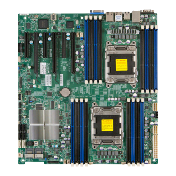
One (1) Supermicro Mainboard • Two (2) Serial ATA cables (CBL-0044Lx2) • Two (2) I-Pass to Serial ATA cables (CBL-097L-03 x2) (for X9DR3-F) • One (1) I-Pass to Serial ATA cables (CBL-097L-03) (for X9DRi-F) • One (1) I/O Shield (MCP-260-00042-0N) •... - Page 10 X9DR3-F/X9DRi-F Motherboard User’s Manual Motherboard Image Note: All graphics shown in this manual were based upon the latest PCB Revision available at the time of publishing of the manual. The motherboard you've received may or may not look exactly the same as the graphics...
-
Page 11: Motherboard Layout
Chapter 1: Overview Motherboard Layout COM1 LAN2 LAN1 USB 2/3 USB 0/1 JPB1 JPL1 CTRL KB/Mouse CTRL IPMI_LAN JPG1 FAN6 FAN5 COM2 CPU2 JIPMB1 JRK1 JPME1 X9DR3/i-F USB6 Battery Rev. 1.11a JITP0 CPU1 C602/ C606 BIOS FANB JOH1 FAN4 FANA FAN1 SCU0~3 SCU4~7... - Page 12 X9DR3-F/X9DRi-F Motherboard User’s Manual X9DR3-F/X9DRi-F Quick Reference COM1 LAN2 LAN1 USB 2/3 USB 0/1 JPB1 CTRL JPL1 KB/Mouse CTRL IPMI_LAN JPG1 FAN6 FAN5 COM2 CPU2 JIPMB1 JRK1 JPME1 X9DR3/i-F USB6 Battery Rev. 1.11a JITP0 CPU1 C602/ C606 BIOS FANB JOH1...
- Page 13 PS2 Keyboard/Mouse (optional) LAN1/LAN2 G-bit Ethernet Ports 1/2 (IPMI) LAN IPMI_Dedicated LAN SCU 0~3, 4~7 Storage Control Unit (SCU) Connectors 0~3, 4~7 (SCU 4~7: X9DR3-F only) Onboard Buzzer (Internal Speaker) Slot2, Slot4, Slot6 CPU1 Slot2/CPU2 Slot4/CPU2 Slot6 PCI-Exp. 3.0 x16...
- Page 14 X9DR3-F/X9DRi-F Motherboard User’s Manual Slot1, Slot3, Slot5 CPU1 Slot1/CPU1 Slot3/CPU2 Slot5 PCI-Exp. 3.0 x8 T-SGPIO 1/2 Serial_Link General Purpose I/O Headers BP USB 0/1, 2/3 Back Panel USB 0/1, 2/3 USB 4/5, USB 6, USB Front Panel Accessible USB Connections...
-
Page 15: Motherboard Features
Chapter 1: Overview Motherboard Features • Dual Intel E5-2600(v2) Series Processors (Socket ® R LGA2011); each processor supports four full-width Intel QuickPath Interconnect (QPI) links (with support of up to 25.6 GT/s per QPI link and with Data Trans- fer Rate of up to 8.0 GT/s per direction). Note: For Intel E5-2600(v2) processor support, BIOS version 3.0 or above is required. -
Page 16: Peripheral Devices
SCU (Storage Control Unit) Connections • SCU Ports 0~3, 4~7 (X9DR3-F) 0~3 (X9DRi-F) • RAID Support RAID 0, 1, 10 (X9DR3-F) RAID 0, 1, 5, 10 (X9DRi-F) Integrated IPMI 2.0 • IPMI 2.0 supported by the WPCM450R BMC Serial (COM) Port •... - Page 17 Chapter 1: Overview • CPU/System overheat LED and control • CPU Thermal Trip support • Thermal Monitor 2 (TM2) support Fan Control • Fan status monitoring with firmware thermal man- agement via IPMI 2.0 • Low noise fan speed control •...
-
Page 18: System Block Diagram
X9DR3-F/X9DRi-F Motherboard User’s Manual #1-8 #1-7 #1-6 #2-8 #1-5 #2-7 #2-6 #1-4 #2-5 #1-3 #2-4 #1-2 #2-3 #1-1 #2-2 E5-2600(v2) Series E5-2600(v2) Series #2-1 Processor#1 Processor#2 DDR3 DDR3 #2 #3A #3B #1B DMI2 DMI2 PCI-E X16 G3 PCI-E X16 G3... -
Page 19: Processor And Chipset Overview
Built upon the functionality and the capability of Intel E5-2600(v2) Series Proces- ® sor (Socket R LGA 2011) and the PCH C606/C602 chipset, the X9DR3-F/X9DRi-F motherboard provides the performance and feature sets required for dual_proces- sor-based HPC/Cluster/Database servers. (See note below for processor support.) -
Page 20: Special Features
X9DR3-F/X9DRi-F Motherboard User’s Manual Special Features Recovery from AC Power Loss The Basic I/O System (BIOS) provides a setting that determines how the system will respond when AC power is lost and then restored to the system. You can choose for the system to remain powered off (in which case you must press the power switch to turn it back on), or for it to automatically return to the power-on state. -
Page 21: Acpi Features
It is even more important for processors that have high CPU clock rates. The X9DR3-F/X9DRi-F motherboard accommodates 24-pin ATX power supplies. Although most power supplies generally meet the specifications required by the CPU, some are inadequate. In addition, two 12V 8-pin power connections are also required to ensure adequate power supply to the system. -
Page 22: Super I/O
X9DR3-F/X9DRi-F Motherboard User’s Manual It is strongly recommended that you use a high quality power supply that meets ATX power supply Specification 2.02 or above. It must also be SSI compliant. (For more information, please refer to the Website at http://www.ssiforum.org/). Additionally, in areas where noisy power transmission is present, you may choose to install a line filter to shield the computer from noise. -
Page 23: Overview Of The Nuvoton Wpcm450 Controller
Chapter 1: Overview Overview of the Nuvoton WPCM450 Controller The Nuvoton WPCM450R Controller, a Baseboard Management Controller (BMC), supports 2D/VGA-compatible Graphic Cores with PCI interface, creating multi-media virtualization via Keyboard/Video/Mouse Redirection (KVMR). The WPCM450R Controller is ideal for remote system management. The WPCM450R Controller interfaces with the host system via PCI connections to communicate with the graphics cores. - Page 24 X9DR3-F/X9DRi-F Motherboard User’s Manual • RMCP+ protocol supported Note 1: For more information on IPMI configuration, please refer to the IPMI User's Guide posted on our website at http://www.supermicro.com/ support/manuals/. Note 2: The term "IPMI controller" and the term "BMC controller" can be used interchangeably in this section.
-
Page 25: Chapter 2 Installation
Chapter 2: Installation Chapter 2 Installation Standardized Warning Statements The following statements are industry-standard warnings, provided to warn the user of situations which have the potential for bodily injury. Should you have questions or experience difficulty, contact Supermicro's Technical Support department for assis- tance. - Page 26 X9DR3-F/X9DRi-F Motherboard User’s Manual Attention Danger d'explosion si la pile n'est pas remplacée correctement. Ne la remplacer que par une pile de type semblable ou équivalent, recommandée par le fabricant. Jeter les piles usagées conformément aux instructions du fabricant. ¡Advertencia! Existe peligro de explosión si la batería se reemplaza de manera incorrecta.
-
Page 27: Product Disposal
Chapter 2: Installation Product Disposal Warning! Ultimate disposal of this product should be handled according to all national laws and regulations. 製品の廃棄 この製品を廃棄処分する場合、 国の関係する全ての法律 ・ 条例に従い処理する必要が あります。 警告 本产品的废弃处理应根据所有国家的法律和规章进行。 警告 本產品的廢棄處理應根據所有國家的法律和規章進行。 Warnung Die Entsorgung dieses Produkts sollte gemäß allen Bestimmungen und Gesetzen des Landes erfolgen. -
Page 28: Static-Sensitive Devices
X9DR3-F/X9DRi-F Motherboard User’s Manual Static-Sensitive Devices Electrostatic Discharge (ESD) can damage electronic com ponents. To avoid dam- aging your system board, it is important to handle it very carefully. The following measures are generally sufficient to protect your equipment from ESD. -
Page 29: Processor And Heatsink Installation
Chapter 2: Installation Processor and Heatsink Installation Warning: When handling the processor package, avoid placing direct pressure on the label area. Notes: • Always connect the power cord last, and always remove it before adding, removing or changing any hardware components. Make sure that you install the processor into the CPU socket before you install the CPU heatsink. - Page 30 X9DR3-F/X9DRi-F Motherboard User’s Manual 2. Press the second load lever labeled 'Close 1st' to release the load plate that covers the CPU socket from its locking position. Press down on Load the Pull lever away from Lever labeled 'Close 1st' the socket 3.
- Page 31 Chapter 2: Installation 1. Using your thumb and the index finger, remove the 'WARNING' plastic cap from the socket. 2. Use your thumb and index finger to hold the CPU on its edges. Align the CPU keys, which are semi-circle cutouts, against the socket keys. Socket Keys CPU Keys 3.
- Page 32 X9DR3-F/X9DRi-F Motherboard User’s Manual 4. With the CPU inside the socket, inspect the four corners of the CPU to make sure that the CPU is properly installed. 5. Close the load plate with the CPU inside the socket. Lock the lever labeled 'Close 1st' first, then lock the lever labeled 'Open 1st' second.
-
Page 33: Installing A Passive Cpu Heatsink
Chapter 2: Installation Installing a Passive CPU Heatsink 1. Do not apply any thermal grease to the heatsink or the CPU die -- the re- quired amount has already been applied. 2. Place the heatsink on top of the CPU so that the four mounting holes are aligned with those on the Motherboard's and the Heatsink Bracket under- neath. -
Page 34: Removing The Heatsink
X9DR3-F/X9DRi-F Motherboard User’s Manual Removing the Heatsink Warning: We do not recommend that the CPU or the heatsink be removed. However, if you do need to uninstall the heatsink, please follow the instructions below to uninstall the heatsink to prevent damage done to the CPU or the CPU socket. -
Page 35: Installing And Removing The Memory Modules
Chapter 2: Installation Installing and Removing the Memory Modules Note: Check Supermicro's website for recommended memory modules. CAUTION Exercise extreme care when installing or removing DIMM modules to prevent any possible damage. Installing & Removing DIMMs 1. Insert the desired number of DIMMs into the memory slots, starting with P1-DIMMA1. - Page 36 X9DR3-F/X9DRi-F Motherboard User’s Manual Memory Support for the X9DR3-F/X9DRi-F Motherboard The X9DR3-F/X9DRi-F motherboard supports up to 1 TB of Load Reduced (LRDIMM), 512 GB of Registered (RDIMM) or 128 GB of Unbuffered (UDIMM) ECC/Non-ECC DDR3 800/1066/1333/1600/1866 MHz 240-pin 4-channel memory modules in 16 DIMM slots.
- Page 37 Chapter 2: Installation Populating UDIMM (ECC/Non-ECC) Memory Modules Intel E5-2600(v2) Series Processor UDIMM Memory Support Ranks Memory Capacity Speed (MT/s) and Voltage Validated by Slot per Channel (SPC) and Per DIMM DIMM Per Channel (DPC) DIMM 2 Slots Per Channel 3 Slots Per Channel &...
- Page 38 X9DR3-F/X9DRi-F Motherboard User’s Manual Populating UDIMM (ECC/Non-ECC) Memory Modules Intel E5-2600 Series Processor UDIMM Memory Support Ranks Memory Capacity Speed (MT/s) and Voltage Validated by Slot per Channel (SPC) and Per DIMM DIMM Per Channel (DPC) DIMM 2 Slots Per Channel 3 Slots Per Channel &...
- Page 39 Chapter 2: Installation Populating LRDIMM (ECC) Memory Modules Intel E5-2600(v2) Series Processor LRDIMM Memory Support Ranks Memory Speed (MT/s) and Voltage Validated by Slot per Channel (SPC) and DIMM Per Capacity Channel (DPC) DIMM Per DIMM 2 Slots Per Channel 3 Slots Per Channel &...
-
Page 40: Motherboard Installation
X9DR3-F/X9DRi-F Motherboard User’s Manual Motherboard Installation All motherboards have standard mounting holes to fit different types of chassis. Make sure that the locations of all the mounting holes for both motherboard and chassis match. Although a chassis may have both plastic and metal mounting fas- teners, metal ones are highly recommended because they ground the motherboard to the chassis. -
Page 41: Installing The Motherboard
Chapter 2: Installation Installing the Motherboard 1. Install the I/O shield into the chassis. 2. Locate the mounting holes on the motherboard. 3. Locate the matching mounting holes on the chassis. Align the mounting holes on the motherboard against the mounting holes on the chassis. 4. -
Page 42: Control Panel Connectors And I/O Ports
X9DR3-F/X9DRi-F Motherboard User’s Manual Control Panel Connectors and I/O Ports The I/O ports are color coded in conformance with the PC 99 specification. See the picture below for the colors and locations of the various I/O ports. Back Panel Connectors and I/O Ports... -
Page 43: Serial Ports
Chapter 2: Installation Serial Ports Serial COM) Ports Pin Definitions Two COM connections (COM1 & Pin # Definition Pin # Definition COM2) are located on the mother- board. COM1 is located on the Back- plane I/O panel. COM2, located close to PCI-E Slot1, provides front access support. -
Page 44: Universal Serial Bus (Usb)
X9DR3-F/X9DRi-F Motherboard User’s Manual Universal Serial Bus (USB) FP USB (4/5, 8/9, 10/11, USB 6) Backplane Pin Definitions USB (0/1, 2/3) Four Universal Serial Bus ports (USB Pin Definitions USB 4, 8,10, 6, 7 USB 5, 9, 11 0/1, USB 2/3) are located on the... -
Page 45: Ethernet Ports
Chapter 2: Installation Ethernet Ports LAN Ports Pin Definition Two Gigabit Ethernet ports (LAN1, Pin# Definition LAN2) are located on the I/O back- P2V5SB SGND plane on the motherboard. In addition, TD0+ Act LED an IPMI_Dedicated LAN is located TD0- P3V3SB above USB 0/1 ports on the backplane TD1+ Link 100 LED (Yel-... -
Page 46: Front Control Panel
X9DR3-F/X9DRi-F Motherboard User’s Manual Front Control Panel JF1 contains header pins for various buttons and indicators that are normally lo- cated on a control panel at the front of the chassis. These connectors are designed specifically for use with Supermicro's server chassis. See the figure below for the descriptions of the various control panel buttons and LED indicators. -
Page 47: Front Control Panel Pin Definitions
Chapter 2: Installation Front Control Panel Pin Definitions NMI Button NMI Button Pin Definitions (JF1) The non-maskable interrupt button Pin# Definition header is located on pins 19 and 20 Control of JF1. Refer to the table on the right Ground for pin definitions. Power LED Power LED Pin Definitions (JF1) The Power LED connection is located Pin#... -
Page 48: Hdd Led
X9DR3-F/X9DRi-F Motherboard User’s Manual HDD LED HDD LED Pin Definitions (JF1) The HDD LED connection is located Pin# Definition on pins 13 and 14 of JF1. Attach a 3.3V Standby cable here to indicate HDD activ- HD Active ity. See the table on the right for pin definitions. -
Page 49: Overheat (Oh)/Fan Fail Led
Chapter 2: Installation Overheat (OH)/Fan Fail LED OH/Fan Fail/PWR Fail LED Pin Definitions (JF1) Connect an LED cable to pins 7 and 8 Pin# Definition of JF1 to provide advanced warnings of chassis overheating and fan failure. OH/Fan Fail LED) Refer to the table on the right for pin OH/Fan Fail Indicator definitions. -
Page 50: Reset Button
X9DR3-F/X9DRi-F Motherboard User’s Manual Reset Button Reset Button Pin Definitions (JF1) The Reset Button connection is located Pin# Definition on pins 3 and 4 of JF1. Attach it to a Reset hardware reset switch on the computer Ground case. Refer to the table on the right for pin definitions. -
Page 51: Connecting Cables
Chapter 2: Installation Connecting Cables ATX Power 24-pin Connector Pin Definitions Pin# Definition Pin # Definition Power Connectors +3.3V +3.3V -12V +3.3V A 24-pin main power supply connector(J22) and two 8-pin CPU PWR connectors PS_ON (JPWR1/2) are located on the motherboard. These power connectors meet the SSI EPS 12V specification. -
Page 52: Fan Headers
X9DR3-F/X9DRi-F Motherboard User’s Manual Fan Headers Fan Header Pin Definitions This motherboard has eight system/CPU Pin# Definition fan headers (Fan 1~Fan 10, Fan A, Fan Ground B) on the motherboard. All these 4-pin +12V fans headers are backward compatible Tachometer with the traditional 3-pin fans. The fan... -
Page 53: Internal Speaker
Chapter 2: Installation Internal Speaker Internal Buzzer (SP1) Pin Definition The Internal Speaker, located at SP1, Pin# Definitions can be used to provide audible indica- Pin 1 Pos. (+) Beep In tions for various beep codes. See the Pin 2 Neg. (-) Alarm table on the right for pin definitions. -
Page 54: Tpm Header/Port 80
X9DR3-F/X9DRi-F Motherboard User’s Manual TPM Header/Port 80 TPM/Port 80 Header Pin Definitions A Trusted Platform Module/Port 80 Pin # Definition Pin # Definition header is located at JTPM1 to provide LCLK TPM support and Port 80 connection. LFRAME# <(KEY)> Use this header to enhance system... -
Page 55: Power Smb (I 2 C) Connector
Chapter 2: Installation Power SMB (I C) Connector PWR SMB Pin Definitions Power System Management Bus (I Pin# Definition Connector (JI C1) monitors power Clock supply, fan and system temperatures. Data See the table on the right for pin PWR Fail definitions. -
Page 56: T-Sgpio 1/2 Headers
X9DR3-F/X9DRi-F Motherboard User’s Manual T-SGPIO 1/2 Headers T-SGPIO Pin Definitions Two SGPIO (Serial-Link General Pin# Definition Definition Purpose Input/Output) headers are located on the motherboard. These Ground Data headers support Serial_Link interface Load Ground for onboard SATA connections. See Clock the table on the right for pin defini- Note: NC= No Connection tions. -
Page 57: Jumper Settings
Chapter 2: Installation Jumper Settings Explanation of Jumpers Connector Pins To modify the operation of the mother- board, jumpers can be used to choose between optional settings. Jumpers create Jumper shorts between two pins to change the function of the connector. Pin 1 is identified with a square solder pad on the printed circuit board. -
Page 58: Cmos Clear
X9DR3-F/X9DRi-F Motherboard User’s Manual CMOS Clear JBT1 is used to clear CMOS. Instead of pins, this "jumper" consists of contact pads to prevent accidental clearing of CMOS. To clear CMOS, use a metal object such as a small screwdriver to touch both pads at the same time to short the connection. -
Page 59: Vga Enable
Chapter 2: Installation VGA Enable VGA Enable Jumper Settings Jumper JPG1 allows the user to enable Jumper Setting Definition the onboard VGA connector. The default Enabled (Default) setting is 1-2 to enable the connection. Disabled See the table on the right for jumper settings. -
Page 60: Management Engine (Me) Recovery
X9DR3-F/X9DRi-F Motherboard User’s Manual Management Engine (ME) Recovery ME Recovery Jumper Settings Use Jumper JPME1 to select ME Firm- Jumper Setting Definition ware Recovery mode, which will limit Normal (Default) resource allocation for essential system ME Recovery operation only in order to maintain nor- mal power operation and management. -
Page 61: Onboard Led Indicators
Chapter 2: Installation Onboard LED Indicators GLAN LEDs Link Speed LED Activity LED There are two GLAN ports on the moth- erboard. Each Gigabit Ethernet LAN port Rear View (when facing the rear side of the chassis) has two LEDs. The Yellow LED on the GLAN Activity Indicator (Right) right indicates connection and activity. -
Page 62: Onboard Power Led
X9DR3-F/X9DRi-F Motherboard User’s Manual Onboard Power LED Onboard PWR LED Indicator (LE1) LED Settings An Onboard Power LED is located at LE1 LED Color Definition on the motherboard. When this LED is on, System Off (PWR cable not connected) the system is on. Be sure to turn off the... -
Page 63: 2-10 Serial Ata Connections
Eight SCU (Storage Control Unit) Ports (SCU 0~3, 4~7) are located on the X9DR3-F and four SCU (SCU 0~3) ports are on the X9DRi-F to provide serial link connections. These ports are supported by the Intel PCH. See the table on the right for pin definitions. - Page 64 X9DR3-F/X9DRi-F Motherboard User’s Manual Notes 2-40...
-
Page 65: Chapter 3 Troubleshooting
Chapter 3: Troubleshooting Chapter 3 Troubleshooting Troubleshooting Procedures Use the following procedures to troubleshoot your system. If you have followed all of the procedures below and still need assistance, refer to the ‘Technical Support Procedures’ and/or ‘Returning Merchandise for Service’ section(s) in this chapter. Note: Always disconnect the power cord before adding, changing or installing any hardware components. -
Page 66: System Boot Failure
X9DR3-F/X9DRi-F Motherboard User’s Manual No Video 1. If the power is on, but you have no video, remove all the add-on cards and cables. 2. Use the speaker to determine if any beep codes exist. Refer to Appendix A for details on beep codes. -
Page 67: Memory Errors
Chapter 3: Troubleshooting Memory Errors When a No-Memory Beep Code is issued by the system, check the following: 1. Make sure that the memory modules are compatible with the system and that the DIMM modules are properly and fully installed. (For memory compatibility, refer to the Memory Compatibility Chart posted on our Website @ http://www. - Page 68 X9DR3-F/X9DRi-F Motherboard User’s Manual 4. System cooling: Check system cooling to make sure that all heatsink fans, and CPU/system fans, etc., work properly. Check Hardware Monitoring set- tings in the BIOS to make sure that the CPU and System temperatures are within the normal range.
-
Page 69: Technical Support Procedures
Chapter 3: Troubleshooting Technical Support Procedures Before contacting Technical Support, please take the following steps. Also, please note that as a motherboard manufacturer, Supermicro also sells motherboards through its channels, so it is best to first check with your distributor or reseller for troubleshooting services. -
Page 70: Battery Removal And Installation
X9DR3-F/X9DRi-F Motherboard User’s Manual Battery Removal and Installation Battery Removal To remove the onboard battery, follow the steps below: 1. Power off your system and unplug your power cable. 2. Locate the onboard battery as shown below. 3. Using a tool such as a pen or a small screwdriver, push the battery lock out- wards to unlock it. -
Page 71: Frequently Asked Questions
Chapter 3: Troubleshooting Frequently Asked Questions Question: What are the various types of memory that my motherboard can support? Answer: The motherboard supports Registered/Load Reduced ECC or Unbuffered ECC/Non-ECC DDR3 DIMM modules. To enhance memory performance, do not mix memory modules of different speeds and sizes. Please follow all memory installation instructions given on Section 2-4 in Chapter 2. -
Page 72: Returning Merchandise For Service
X9DR3-F/X9DRi-F Motherboard User’s Manual Returning Merchandise for Service A receipt or copy of your invoice marked with the date of purchase is required before any warranty service will be rendered. You can obtain service by calling your ven- dor for a Returned Merchandise Authorization (RMA) number. When returning the... -
Page 73: Chapter 4 Bios
BIOS Introduction This chapter describes the AMI BIOS Setup utility for the X9DR3-F/X9DRi-F. It also provides the instructions on how to navigate the AMI BIOS Setup utility screens. The AMI ROM BIOS is stored in a Flash EEPROM and can be easily updated. -
Page 74: Main Setup
X9DR3-F/X9DRi-F Motherboard User’s Manual Note: For AMI UEFI BIOS Recovery, please refer to the UEFI BIOS Re- covery User Guide posted @http://www.supermicro.com/support/manuals/. Starting the Setup Utility Normally, the only visible Power-On Self-Test (POST) routine is the memory test. As the memory is being tested, press the <F2> key to enter the main menu of the AMI BIOS Setup utility. -
Page 75: 4-3 Advanced Setup Configurations
Day MM/DD/YY format. The time is entered in HH:MM:SS format. (Note: The time is in the 24-hour format. For example, 5:30 P.M. appears as 17:30:00.) X9DR3-F/i SMC Version This item displays the SMC Version of the BIOS used in the system. - Page 76 X9DR3-F/X9DRi-F Motherboard User’s Manual Quiet Boot Set this value to allow the bootup screen options to be modified between POST messages or the OEM logo. Select Disabled to allow the computer system to display the POST messages. Select Enabled to allow the computer system to display the OEM logo.
-
Page 77: Socket 0 Cpu Information
Chapter 4: AMI BIOS CPU Configuration This submenu displays the information of the CPU as detected by the BIOS. It also allows the user to configure CPU settings. Socket 0 CPU Information This submenu displays the following information regarding the CPU installed in Socket 0. - Page 78 X9DR3-F/X9DRi-F Motherboard User’s Manual 64-bit This item indicates if the CPU installed in Socket 1 supports 64-bit technology. Hyper-threading Select Enabled to support Intel Hyper-threading Technology to enhance CPU performance. The options are Enabled and Disabled. Active Processor Cores Set to Enabled to use a processor's Second Core and beyond. (Please refer to Intel's web site for more information.) The options are All, 1, 2, and 4.
- Page 79 Chapter 4: AMI BIOS DCU IP Prefetcher Select Enabled for DCU (Data Cache Unit) IP Prefetcher support, which will prefetch IP addresses to improve network connectivity and system performance. The options are Enabled and Disabled. Intel® Virtualization Technology (Available when supported by the CPU) Select Enabled to support Intel Virtualization Technology, which will allow one platform to run multiple operating systems and applications in independent parti- tions, creating multiple "virtual"...
- Page 80 X9DR3-F/X9DRi-F Motherboard User’s Manual P-STATE Coordination This feature selects the type of coordination for the P-State of the processor. P-State is a processor operational state that reduces the processor's voltage and frequency. This makes the processor more energy efficient, resulting in further gains.
-
Page 81: North Bridge
Chapter 4: AMI BIOS Chipset Configuration North Bridge This feature allows the user to configure the settings for the Intel North Bridge. IOH (IO Hub) Configuration Intel VT-d Select Enabled to enable Intel Virtualization Technology support for Direct I/O VT-d by reporting the I/O device assignments to the VMM (Virtual Working Memory) through the DMAR ACPI Tables. - Page 82 X9DR3-F/X9DRi-F Motherboard User’s Manual Port 1B Link Speed Select GEN1 to enable PCI-Exp Generation 1 support for Port 1B. Select GEN2 to enable PCI-Exp Generation 2 support for Port 1B. Select GEN3 to enable PCI-Exp Generation 3 support for Port 1B. The options are GEN1, GEN2, and GEN3.
- Page 83 Chapter 4: AMI BIOS Port 1A Link Speed Select GEN1 to enable PCI-Exp Generation 1 support for Port 1A. Select GEN2 to enable PCI-Exp Generation 2 support for Port 1A. Select GEN3 to enable PCI-Exp Generation 3 support for Port 1A. The options are GEN1, GEN2, and GEN3.
- Page 84 X9DR3-F/X9DRi-F Motherboard User’s Manual DIMM Configuration • Total Memory: This item displays the total memory size available in the system. • Current Memory Mode: This item displays the current memory mode. • Current Memory Speed: This item displays the current memory speed.
- Page 85 Chapter 4: AMI BIOS DRAM RAPL Mode RAPL which stands for Running Average Power Limit is a feature that provides mechanisms to enforce power consumption limits on supported processors The options are DRAM RAPL MODE0 , DRAM RAPL MODE1, and Disabled. MPST Support Select Enabled to enable the Message Processing Subscriber Terminal which is used to process short messages.
-
Page 86: South Bridge
X9DR3-F/X9DRi-F Motherboard User’s Manual DRAM RAPL RAPL which stands for Running Average Power Limit is a feature that provides mechanisms to enforce power consumption limits on supported processors The options are Mode 0, MODE1, and Disabled. Device Tagging Select Enabled to support device tagging. The options are Disabled and En- abled. - Page 87 Chapter 4: AMI BIOS available for EFI (Extensive Firmware Interface) applications only. The settings are Enabled, Disabled and Auto. Port 60/64 Emulation Select Enabled to enable I/O port 60h/64h emulation support for the legacy USB keyboard so that it can be fully supported by the operating systems that do not recognize a USB device.
- Page 88 X9DR3-F/X9DRi-F Motherboard User’s Manual Port 0~Port 5 Hot Plug Select Enabled to enable hot-plug support for a port specified by the user so that the user is allowed to change a hardware component or a device without shutting down the system. The options are Enabled and Disabled.
- Page 89 Chapter 4: AMI BIOS ME SMBus Thermal Reporting This feature appears when Thermal Management is set to Enabled. Select Enabled to support ME SMBus (Management Engine System Management Bus) reporting. The options are Enabled and Disabled. If set to Enabled, the following items appear: PCH Temp Read, CPU Energy Read, CPU Temp Read Set the above items to Enabled to activate these monitors.
- Page 90 X9DR3-F/X9DRi-F Motherboard User’s Manual Maximum Payload This feature selects the setting for the PCIE maximum payload size. The options are Auto, 128 Bytes, 256 Bytes, 512 Bytes, 1024 Bytes, 2048 Bytes, and 4096 Bytes. Maximum Read Request This feature selects the setting for the PCIE maximum Read Request size. The options are Auto, 128 Bytes, 256 Bytes, 512 Bytes, 1024 Bytes, 2048 Bytes, and 4096 Bytes.
-
Page 91: Serial Port Console Redirection
Chapter 4: AMI BIOS Serial Port 0 Configuration/Serial Port 1 Configuration The submenus allow the user to configure the following settings for Serial Port 0 or Serial Port 1: Serial Port Select Enabled to enable a serial port specified by the user. The options are Enabled and Disabled. - Page 92 X9DR3-F/X9DRi-F Motherboard User’s Manual character set. Select VT-UTF8 to use UTF8 encoding to map Unicode characters into one or more bytes. The options are ANSI, VT100, VT100+, and VT-UTF8. Bits Per Second This item sets the transmission speed for a serial port used in Console Redirec- tion.
-
Page 93: Console Redirection Settings
Chapter 4: AMI BIOS Resolution 100x31 Select Enabled for extended-terminal resolution support. The options are Dis- abled and Enabled. Legacy OS Redirection Use this feature to select the number of rows and columns used in Console Redirection for legacy OS support. The options are 80x24 and 80x25. Putty Keypad Use this feature to select function key and keypad setting on Putty. -
Page 94: Acpi Settings
X9DR3-F/X9DRi-F Motherboard User’s Manual Flow Control This feature allows the user to set the flow control for Console Redirection to prevent data loss caused by buffer overflow. Send a "Stop" signal to stop send- ing data when the receiving buffer is full. Send a "Start" signal to start sending data when the receiving buffer is empty. - Page 95 Chapter 4: AMI BIOS Current Status Information: This item displays the information regarding the current TPM status. TPM Enable Status If a security device is detected by the BIOS, this item displays the status of TPM Support to indicate if TPM is currently enabled or disabled. TPM Active Status If a security device is detected by the BIOS, this item displays the status of TPM Support to indicate if TPM is currently active or deactivated.
-
Page 96: Event Logs
X9DR3-F/X9DRi-F Motherboard User’s Manual Event Logs Use this menu to configure Event Log settings. Change SmBIOS Event Log Settings Enabling/Disabling Options Smbios Event Log Change this item to enable or disable all features of the Smbios Event Logging during boot. The options are Enabled and Disabled. - Page 97 Chapter 4: AMI BIOS MECI The Multiple Event Count Increment (MECI) counter counts the number of oc- curences a duplicate event must happen before the MECI counter is incremented. This is a numeric value ranging from 1 to 255. METW The Multiple Event Time Window (METW) defines number of minutes must pass between duplicate log events before MECI is incremented.
-
Page 98: Ipmi
X9DR3-F/X9DRi-F Motherboard User’s Manual IPMI Use this menu to configure Intelligent Platform Management Interface (IPMI) set- tings. System Event Log Enabling/Disabling Options SEL Components Select Enabled for all system event logging at bootup. The options are Enabled and Disabled. - Page 99 Chapter 4: AMI BIOS Log EFI Status Codes Select Enabled to log EFI (Extensible Firmware Interface) Status Codes, Error Codes or Progress Codes. The options are Disabled and Enabled. Note: After making changes on a setting, be sure to reboot the system for the changes to take effect.
-
Page 100: Boot
X9DR3-F/X9DRi-F Motherboard User’s Manual Boot This menu allows the user to configure the following boot settings for the system. Boot Option Priorities Boot Option #1/ Boot Option #2/ Boot Option #3 Use this feature to specify the sequence of boot device priority. -
Page 101: Security
Chapter 4: AMI BIOS Security This menu allows the user to configure the following security settings for the system. Administrator Password Use this feature to set the Administrator Password which is required to enter the BIOS setup utility. The length of the password should be from 3-characters to 8-characters long. -
Page 102: Save & Exit
X9DR3-F/X9DRi-F Motherboard User’s Manual Save & Exit This menu allows the user to configure the Save and Exit settings for the system. Discard Changes and Exit Select this option to quit the BIOS Setup without making any permanent changes to the system configuration, and reboot the computer. Select Discard Changes and Exit, and press <Enter>. - Page 103 Chapter 4: AMI BIOS Discard Changes Select this feature and press <Enter> to discard all the changes and return to the BIOS setup. When the dialog box appears, asking you if you want to load previ- ous values, click Yes to load the values previous saved, or click No to keep the changes you've made so far.
- Page 104 X9DR3-F/X9DRi-F Motherboard User’s Manual Notes 4-32...
-
Page 105: Appendix A Bios Error Beep Codes
Appendix A: BIOS POST Error Codes Appendix A BIOS Error Beep Codes During the POST (Power-On Self-Test) routines, which are performed at each system boot, errors may occur. Non-fatal errors are those which, in most cases, allow the system to continue to boot. - Page 106 X9DR3-F/X9DRi-F Motherboard User’s Manual Notes...
-
Page 107: Appendix B Software Installation Instructions
Appendix B: Software Installation Instructions Appendix B Software Installation Instructions B-1 Installing Software Programs After you've installed the operating system, a screen as shown below will appear. You are ready to install software programs and drivers that have not yet been in- stalled. -
Page 108: Configuring Superdoctor® Iii
X9DR3-F/X9DRi-F Motherboard User’s Manual Note 3: Changing BMC log-in information is recommended during initial sys- tem power-on. The default username is ADMIN and password is ADMIN. For BMC best practices, please refer to: http://www.supermicro.com/products/ nfo/files/IPMI/Best_Practices_BMC_Security.pdf B-2 Configuring SuperDoctor III The SuperDoctor® III program is a Web-based management tool that supports remote management capability. - Page 109 Appendix B: Software Installation Instructions SuperDoctor® III Interface Display Screen-II (Remote Control) Note: The SD III utility and user guide can be downloaded from our website at: http://www.supermicro.com/products/accessories/software/ SuperDoctorIII.cfm. For Linux, we will still recommend that you use SuperDoctor II.
- Page 110 X9DR3-F/X9DRi-F Motherboard User’s Manual Notes...
- Page 111 (Disclaimer Continued) The products sold by Supermicro are not intended for and will not be used in life support systems, medical equipment, nuclear facilities or systems, aircraft, aircraft devices, aircraft/emergency communication devices or other critical systems whose failure to perform be reasonably expected to result in significant injury or loss of life or catastrophic property damage.
Need help?
Do you have a question about the X9DR3-F and is the answer not in the manual?
Questions and answers