
Subscribe to Our Youtube Channel
Related Manuals for Generac Power Systems 00940-2


Summary of Contents for Generac Power Systems 00940-2
-
Page 1: Installation Instructions
® POWER SYSTEMS, INC. Owner’s Manual and Installation Instructions Air-cooled Recreational Vehicle Generator • Model Nos: 00940-2 & 00941-2 IMPACT-36 plus II with Inverter... -
Page 2: Introduction
ING, CAUTION, and NOTE blocks are used to alert 00940-2 and 00941-2. In addition, the latter portion you to special instructions about a particular oper- of this manual contains information necessary for the ation that may be hazardous if performed incorrect- proper installation of these generators. -
Page 3: Table Of Contents
Exercising the Generator ..........15 Section 5 – Electrical Data............39 3.17 Out of Service Protection ..........15 Section 6 – Exploded Views and Parts Lists ......42 3.18 Return Unit to Service After Storage......15 Section 7 – Warranty..............52 Notes ....................16 Generac ® Power Systems, Inc. -
Page 4: Safety Rules
• Keep hands, feet, clothing, etc., away from drive Generac cannot possibly anticipate every possible cir belts, fans, and other moving or hot parts. Never cumstance that might involve a hazard. The warn-... -
Page 5: Electrical Hazards
Inspect the unit’s fuel system fre- quently and correct any leaks immediately. Before placing this equipment into service, the fuel supply lines must be properly installed, purged, and leak- tested according to applicable fuel-gas codes. Generac ® Power Systems, Inc. -
Page 6: Section 1 - General Information
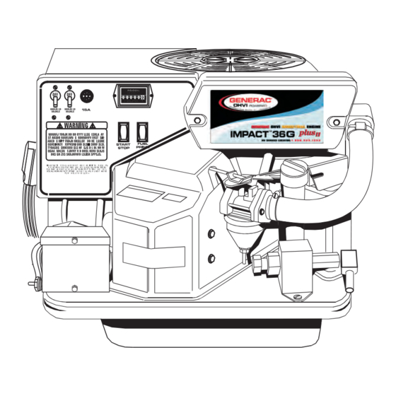
3. Air Intake Tube 10. Engine Start/Stop Switch 4. Oil Dipstick and Filler Tube 11. Generator DC Output Leads 5. Fuel Pump 12. Circuit Breaker 6. Gasoline Carburetor 13. Fuse 7. Fuel Primer Switch 14. Hour Meter Generac ® Power Systems, Inc. -
Page 7: Impact-36Lpg Plus Features
11. Engine Start/Stop Switch 4. LP Fuel Regulator 12. Generator DC Output Leads 5. Oil Dipstick and Filler Tube 13. Circuit Breaker 6. LP Carburetor 14. Fuse 7. LP Fuel Solenoid 15. Hour Meter 8. Fuel Primer Switch Generac ® Power Systems, Inc. -
Page 8: Inverter Features
Section 1 – General Information IMPACT-36 plus II Recreational Vehicle Generator 1.1.3 INVERTER FEATURES (PART NO. 0D4885) REFERENCE NUMBER IDENTIFICATION 1. Inverter 4. DC Input 2. 12 Pin Connection 5. Cooling Fan 3. Customer AC Output Generac ® Power Systems, Inc. -
Page 9: Generator Applicability
RULES to prevent accidents and damage to it for any application other than for what it was equipment and/or property. Generac suggests copy- designed. If there are questions pertaining to its ing and posting the GENERAL SAFETY RULES in application, write or call the factory. -
Page 10: Hour Meter
1.6.1.1 Initial Startup During initial startup, a time delay built into the shut- down control system allows oil pressure to build. The delay allows the engine to run for about 10 seconds before sensing oil pressure. Generac ® Power Systems, Inc. -
Page 11: Section 2 - Operation
START. Release the switch when the Close windows, doors and other openings in the vehi- engine starts. cle that, if open, might permit exhaust gases to enter the vehicle. Generac ® Power Systems, Inc. -
Page 12: Stopping The Generator
Holding the switch for any submersion in water, have an authorized longer than 15 seconds may damage the Generac Service Facility thoroughly clean and dry the starter motor. generator. 3. Let the engine run at no-load for a few minutes to stabilize and warm up the engine. -
Page 13: Fuel Requirements (Lp Units)
Section 2 – Operation IMPACT-36 plus II Recreational Vehicle Generator 2.11 GAS GENERATOR SPECIFICATIONS Model ..........Impact-36G plus II Generac does not recommend using any gaso- Rated Maximum Continuous line containing alcohol, it must not contain AC Power Output ......3600 watts (3.6 kW) more than 10 percent ethanol and it must be Rated Voltage ..........120 volts AC... -
Page 14: Section 3 - Maintenance
Then tighten an addi- tional 3/4 to one turn by hand. • Run engine and check for leaks. NOTE: Check oil level and fill to full mark after checking for leaks. Filter will retain some oil. 12 Generac ® Power Systems, Inc. -
Page 15: Engine Air Cleaner
Inspect the area around the generator exhaust muf- fler periodically and remove all grass, leaves, dirt, etc. from this area. Fuel Filter Figure 3.4 — Clean Air Intake Screen Air Intake Screen Customer Fuel Connection Generac ® Power Systems, Inc. 13... -
Page 16: Inverter
Also check battery fluid level, and, if necessary, fill your generator is used at altitudes in excess of 5,000 with DISTILLED WATER ONLY. DO NOT USE TAP feet, consult your Generac Authorized Service Facility WATER IN BATTERY. regarding high altitude jetting changes. -
Page 17: Adjusting Valve Clearance
Correct clearance is 0.001-0.003 inch (0.03-0.07mm). Adjust valve clearance as follows: Generac recommends that you start and operate the generator at least once every seven days. Let the unit 1. Loosen the rocker arm jam nut. Use an allen run for at least 30 minutes to “exercise”... -
Page 18: Notes
Notes IMPACT-36 plus II Recreational Vehicle Generator 16 Generac ® Power Systems, Inc. -
Page 19: Part Ii - Installation Instructions
PART II – INSTALLATION INSTRUCTIONS ONLY QUALIFIED ELECTRICIANS OR CONTRACTORS SHOULD ATTEMPT INSTALLATION!! -
Page 20: Safety Rules
(a) use of common hand tools, breathed in sufficient concentrations, can cause unconsciousness or even death. This exhaust sys- (b) use of special Generac tools, and (c) use of any tools and/or equipment from other suppliers. tem must be installed properly, in strict compli- ance with applicable codes and standards. - Page 21 • Never wear jewelry when working on this equip- connection point and the rigid fuel lines. ment. Jewelry can conduct electricity, resulting in electric shock, or may get caught in moving com- ponents, causing injury. Generac ® Power Systems, Inc. 19...
-
Page 22: Section 1 - General Information
Instructions and information in this section pertain The installation should comply strictly with all to Generac Impact air-cooled generators — more applicable codes, standards, and regulations pertain- specifically, the installation of Impact-34 plus II and ing to the installation and use of this product. -
Page 23: Section 2 - Installation
• The installer must make certain that selected loca- zontal support tubing or suspended below the tub- tion will permit adequate cooling and ventilating ing, the supporting frame used must be structural- air flow to be supplied. ly sound. Generac ® Power Systems, Inc. 21... -
Page 24: Generator Restraint
• If the compartment is lined with galvanized steel, it ing framework (Figure 2.3). All bolts must be long may be constructed of any material. Generac rec- enough so that when tight, at least 3 threads are vis- ommends that the compartment be constructed of ible past the retaining lock nuts. -
Page 25: Compartment Size
You may need to use approved non-flammable insulating materials in high temperature areas. Generac ® Power Systems, Inc. 23... -
Page 26: Sound Insulating Materials
For example, a sheet of lead or visco-elastic material, along with a layer of other acoustical mate- rial, is more effective than when a single material is used. Figure 2.7 – Compartment Floor Cutout 24 Generac ® Power Systems, Inc. -
Page 27: Acoustics
Generator Do not install any insulation or other absorbent materials on the interior or under- side of the compartment floor. • Seal all compartment door edges to prevent noise leakage around the door perimeter. Generac ® Power Systems, Inc. 25... -
Page 28: Cooling Air Inlet Openings
When the unit is installed on a suspended mounting system, one of several different methods of supplying air flow may be used as follows: • Provide a door in the vehicle skirt having an air inlet opening (Figure 2.11). 26 Generac ® Power Systems, Inc. -
Page 29: Compensating For Restrictions
Gasoline longer than needed, coil the excess near the inverter vapors must not enter the vehicle interior. unit. If a greater length is needed, contact Generac. Factory installed generator fuel system components DO NOT ATTEMPT TO SHORTEN OR LENGTHEN include (a) fuel filter, (b) 12-volt DC electric pump, (c) THE SUPPLIED sensing harnesses. -
Page 30: Generator Fuel Supply Lines
“Standard for Fuel and Oil Hose”. It must be approved for use with gasoline. • The hose should be at least 6 inches longer than is needed to prevent the hose from rupturing if the generator shifts or settles. 28 Generac ® Power Systems, Inc. -
Page 31: Some Important Considerations
NOT attempt to use the kit along with any “liquid attached to the diaphragm opens a valve to permit withdrawal” type system. gas flow through the carburetor. Figure 2.16 — Propane Gas Carburetion Diagram Generac ® Power Systems, Inc. 29... -
Page 32: Fuel Supply Lines
U.S. Forest Service. Use only properly tested the gas system for leaks. To test the mufflers and parts approved by Generac. Any per- system, you need a separate source of 12 volts DC to son(s) installing an unapproved muffler, or an unap- open the gaseous fuel solenoid valve. -
Page 33: Type Of Exhaust System
• Use enough exhaust system hangers to prevent any part of the system from being dislocated. • Use exhaust system parts recommended by Generac. Using unapproved exhaust mufflers and exhaust system parts is the responsibility of the person(s) installing such unauthorized parts. -
Page 34: Wiring
J boxes on the inverter unit (Figure 2.19). The electrical receptacles. Contact your manufacturer or unit is provided with a ground which is connected to dealer for recommendations. the generator and should be connected to the chassis of the recreational vehicle. 32 Generac ® Power Systems, Inc. - Page 35 Section 2 – Installation IMPACT-36 plus II Recreational Vehicle Generator Figure 2.20 — Transfer Switch Isolation Method INVERTER POWER SUPPLY CORD POWER CORD FOR DOCKSIDE POWER Figure 2.21 — Installation with Isolation Receptacle INVERTER Generac ® Power Systems, Inc. 33...
-
Page 36: Sensing Harnesses
• Battery must be a 12 volt, automotive type storage chart. battery. Figure 2.22 — Generator to Inverter Connection 34 Generac ® Power Systems, Inc. -
Page 37: Battery Cable Connections
• Model 004057 includes the remote panel and a 10 where leaks and spills of battery fluid will not cause foot long, 4 wire harness. damage. • Model 004184 includes the remote panel and a 30 foot long, 4 wire harness. Generac ® Power Systems, Inc. 35... -
Page 38: Section 3 - Post-Installation Startup Checks
1. Turn off all electrical loads. Do this by setting the IMPORTANT: GENERAC RECOMMENDS THAT generator main circuit breaker to its “OFF” or YOU TEST THE GENERATOR FOR ADEQUATE “OPEN” position. -
Page 39: Installation Checklist
❑ Check that all other options and accessories (if used) are installed properly. POST INSTALLATION TESTS ❑ Check that all tests are completed properly. DATE OF INSTALLATION ____________________________________________________ NAME OF INSTALLER ______________________________________________________ SIGNATURE OF INSTALLER ________________________________________________ Generac ® Power Systems, Inc. 37... -
Page 40: Section 4 - Troubleshooting
Check vehicle circuit breaker & fuses. Reset and replace if necessary. Transfer sw. set to NORMAL position. Set to GENERATOR position. Generator internal failure. Take generator to an Authorized Generac facility. Inverter defective. Take generator to an Authorized Generac facility. 38 Generac ®... -
Page 42: Section 5 - Electrical Data
Section 5 — Electrical Data IMPACT-36 plus II Recreational Vehicle Generator Wiring Diagram and Schematic – Drawing No. 0D4947-B 40 Generac ® Power Systems, Inc. - Page 43 Section 5 — Electrical Data IMPACT-36 plus II Recreational Vehicle Generator Wiring Diagram and Schematic – Drawing No. 0D4947-B Generac ® Power Systems, Inc. 41...
-
Page 45: Section 6 - Exploded Views And Parts Lists
BLACK TIE WRAP, 7" LG 023762 SHAKEPROOF EXT. #10 0D4885 INVERTER ASSEMBLY 0D4884 WIRE HARNESS 020769 M6 FLAT WASHER 0A6464 WIRE HARNESS-HEATSINK TO PCBI 0D4882 HARNESS-PCBI TO PANEL 0A6700 HARNESS-HEATSINK TO TERM. BLOCK 051714 M3-0.5 NUT Generac ® Power Systems, Inc. 43... - Page 46 Section 6 — Exploded Views and Parts Lists IMPACT-36 plus II Recreational Vehicle Generator Impact-34 plus II Sheet Metal – Drawing No. 0A9193-J 44 Generac ® Power Systems, Inc.
- Page 47 049226 LOCK WASHER, M5 022471 #8-32 HEX NUT 084867 RUBBER "U" CHANNEL 022264 #8 LOCK WASHER 056892 CRIMPTITE #10-24 x 3/8" 079246 HEX HD. CAPS., M6-1.0 x 16MM-W/L- 0A9031 WIRE ASSEMBLY, BLOCKING DIODE WASHER Generac ® Power Systems, Inc. 45...
- Page 48 Section 6 — Exploded Views and Parts Lists IMPACT-36 plus II Recreational Vehicle Generator Impact-36 plus Sheet Metal – Drawing No. 0A9194-H 46 Generac ® Power Systems, Inc.
- Page 49 LOCK WASHER M5 023484D SNAP BUSHING 084867 .5 FT. RUBBER "U" CHANNEL 0A8475 SPECIAL LOCK WASHER, M5 056892 CRIMPTITE #10-24 x 3/8" 022471 #8 HEX NUT 0A9196 COVER, IGNITION SYSTEM 022264 #8 LOCK WASHER Generac ® Power Systems, Inc. 47...
- Page 50 Section 6 — Exploded Views and Parts Lists IMPACT-36 plus II Recreational Vehicle Generator GN 220 RV Long Block – Drawing No. 0A6202-F 48 Generac ® Power Systems, Inc.
- Page 51 COVER, ROCKER 078629 GASKET, BREATHER 090388 BOLT, TAPTITE M6 X 12MM 083153 GEROTOR, OUTER 092977 ASSEMBLY - SUMP, OIL 084186 WASHER, WEAR-VALVE SPRING 088156 SEAL, VALVE-INTAKE 072347 SPARK PLUG, CHAMPION RC12YC 099922 WASHER, WAVE Generac ® Power Systems, Inc. 49...
- Page 52 Section 6 — Exploded Views and Parts Lists IMPACT-36 plus II Recreational Vehicle Generator Generator – Drawing No. 0D4945-A 50 Generac ® Power Systems, Inc.
- Page 53 SCREEN, OIL PICK-UP 036544 P/N, COTTER 3/32" x ½" (940) 0D2446 ADAPTOR, OIL FILTER 089473 ASSEMBLY, BI-METAL & HEATER (940) 0A8584 10 PSI OIL PRESSURE SWITCH 086736 LINKAGE, CHOKE CONTROL (940) 045756 M6-1 x 10MM TAPTITE Generac ® Power Systems, Inc. 51...
-
Page 54: Section 7 - Warranty
Owner’s Manual. For warranty purposes, Generac recommends that you retain all receipts covering maintenance on your engine. However, Generac cannot deny warranty solely because of the lack of receipts or for your failure to ensure the completion of all scheduled maintenance. - Page 55 Such use voids this ECS Warranty and shall be sufficient grounds for disallowing an ECS Warranty claim. Generac shall not be held liable hereunder for failures of any warranted parts of a Generac engine caused by the use of such an unapproved, add-on, modified, counterfeit and/or “grey market”...
- Page 56 NOTE: ALL UNITS MUST BE INSTALLED BY GENERAC POWER SYSTEMS AUTHORIZED SERVICE FACILITIES. For a period of 3 (three) years or 2,000 (two thousand) hours of operation from the date of original sale, whichever occurs first, Generac Power Systems, Inc. (Generac) will, at its option, repair or replace any part which, upon examination, inspection and testing by Generac or a Generac Authorized Warranty Service Dealer, is found to be defective under normal use and service, in accordance with the warranty schedule set forth below.
Need help?
Do you have a question about the 00940-2 and is the answer not in the manual?
Questions and answers