Table of Contents
Advertisement
Quick Links
- 1 Section One - Things You Should Know
- 2 General Information
- 3 Technical Specifications
- 4 Procedure 2.1 - Accessing the Diagnostic Program (Prior to July 21, 1997)
- 5 Procedure 4.1 - Calibrating the Lift
- 6 Procedure 6.4 - Replacing the Lift Motor
- 7 Wiring Diagram 7.1 - 9.21, 9.21I, 9.21S and 9.21Si
- 8 Block Diagram 7.2 - 9.21, 9.21I, 9.21S and 9.21Si
- Download this manual
See also:
Owner's Manual
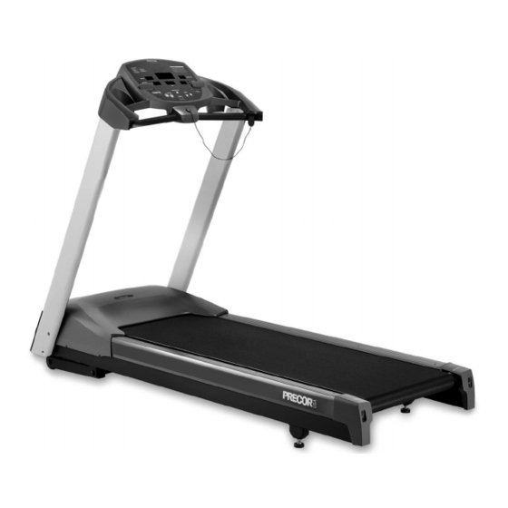
9.21, 9.21i, 9.21S, 9.21Si Treadmill
9.21, 9.21i, 9.21s, 9.21si Treadmill
Warning: This service manual is for use by Precor trained service providers only.
If you are not a Precor Trained Servicer, you must not attempt to service any Precor Product;
Call your dealer for service.
This document contains information required to perform the majority of troubleshooting, and
replacement procedures required to repair and maintain this product.
This document contains general product information, software diagnostic procedures (when
available), preventative maintenance procedures, inspection and adjustment procedures,
troubleshooting procedures, replacement procedures and electrical block and wiring diagrams.
To move directly to a procedure, click the appropriate procedure in the bookmark section to the
left of this page. You may "drag" the separator bar between this page and the bookmark section
to change the size of the page being viewed.
© 2003 Precor Incorporated
Unauthorized Reproduction and Distribution Prohibited By Law
Page 1
Advertisement
Table of Contents
Troubleshooting

Related Manuals for Precor 9.21


Summary of Contents for Precor 9.21
- Page 1 9.21, 9.21i, 9.21s, 9.21si Treadmill Warning: This service manual is for use by Precor trained service providers only. If you are not a Precor Trained Servicer, you must not attempt to service any Precor Product; Call your dealer for service.
-
Page 2: Section One - Things You Should Know
About This Appendix Section One, Things You Should Know. This section includes technical specifications and a procedure matrix. Read this section, as well as the 9.21, 9.21i, 9.21S, 9.21Si Treadmill Owner’s Manual, before you perform the maintenance procedures in this manual. -
Page 3: Technical Specifications
44 inches (117 cm) Running surface: 51 inches by 17 inches (129.5 cm by 43 cm) Motor: 1.7 hp continuous duty (9.21 & 9.21S) 2.0 hp continuous duty (9.21i & 9.21Si) Speed: 0.5 to 10 mph (0.8 to 16 kph) -
Page 4: Procedure 2.1 - Accessing The Diagnostic Program (Prior To July 21, 1997)
Plug the power cord into the wall outlet, then turn on the treadmill with the circuit breaker. Note: Diagram 2.1 illustrates the 9.21 Treadmill display. The 9.21S Treadmill display is shown in Diagram 2.2. Press and hold the STOP, SPEED , SPEED and QUICK START keys simultaneously. - Page 5 9.21, 9.21i, 9.21S, 9.21Si Treadmill Note: When the running belt is started, the number of power bits will be displayed. Power bits are directly related to the drive motor input signal. Press the SPEED keys. Verify that the power bits number increments and decrements as the SPEED keys are pressed.
- Page 6 9.21, 9.21i, 9.21S, 9.21Si Treadmill Diagram 2.2 - 9.21S Display Page 6...
- Page 7 9.21, 9.21i, 9.21S, 9.21Si Treadmill Procedure 2.2 - Accessing the Diagnostic Program (after July 20, 1997) Units built after July 20, 1997 used the standard access codes. The keys on the display are hypothetically numbered for 1 to 7 from left to right. Therefore, ENTER would be key 1, INCLINE would be key 2, etc.
- Page 8 9.21, 9.21i, 9.21S, 9.21Si Treadmill Note: When the running belt is started, the number of power bits will be displayed. Power bits represent the amount of power applied to the drive motor. Power bits are the product of selected speed and applied load.
- Page 9 9.21, 9.21i, 9.21S, 9.21Si Treadmill Procedure 2.3 - Displaying the Odometer (prior to July 21, 1997) This procedure allows you to display the number of miles or kilometers logged on the treadmill. Procedure Plug the power cord into the wall outlet, then turn on the treadmill with the circuit breaker.
-
Page 10: Procedure 2.4 - Displaying The Odometer (After July 20, 1997)
9.21, 9.21i, 9.21S, 9.21Si Treadmill Procedure 2.4 - Displaying the Odometer (after July 20, 1997) The diagnostic program used prior to July 21, 1997 and the diagnostic program used after July 20, 1997 are essentially the same except that the key strokes used to access the programs are different. -
Page 11: Procedure 2.5 - Selecting U.s. Standard Or Metric Units (Prior To July 21, 1997)
9.21, 9.21i, 9.21S, 9.21Si Treadmill Procedure 2.5 - Selecting U.S. Standard or Metric Units (prior to July 21, 1997) Selecting United States standard units causes information to be displayed in feet, miles and pounds. Information is displayed in meters, kilometers and kilograms if metric units are selected. -
Page 12: Procedure 2.6 - Selecting United States Standard Or Metric Units (After July 20, 1997)
9.21, 9.21i, 9.21S, 9.21Si Treadmill Procedure 2.6 - Selecting United States Standard or Metric Units (after July 20, 1997) The diagnostic program used prior to July 21, 1997 and the diagnostic program used after July 20, 1997 are essentially the same except that the key strokes used to access the programs are different. -
Page 13: Procedure 2.7 - Documenting Software Problems
When a problem is found with either the PROM or upper or lower PCA’s, record the information listed below. If you isolated the problem to either the PROM, upper PCA, or lower PCA, include the information with the malfunctioning PROM or PCA when you ship it to Precor Customer Service. - Page 14 9.21, 9.21i, 9.21S, 9.21Si Treadmill Section Three - Checking Treadmill Operation This section provides you with a quick method of checking treadmill operation. Check treadmill operation at the end of a maintenance procedure and when it is necessary to ensure that the treadmill is operating properly.
-
Page 15: Procedure 4.1 - Calibrating The Lift
9.21, 9.21i, 9.21S, 9.21Si Treadmill Procedure 4.1 - Calibrating the Lift WARNING Always turn off the circuit breaker and unplug the treadmill before you remove the treadmill hood. Procedure Remove the hood. Remove the lift motor from the treadmill as described in Procedure 6.4 of this appendix. - Page 16 9.21, 9.21i, 9.21S, 9.21Si Treadmill Note: 1/16" is 1/2 of a revolution of the plastic nut. The white plastic nut must not rotate while you are pressing the either of the INCLINE keys. Exit the diagnostics program. 10. Turn off the treadmill with the circuit breaker, then unplug the treadmill from the wall outlet.
-
Page 17: Procedure 5.1 - Troubleshooting The Keypad And Upper Pca
9.21, 9.21i, 9.21S, 9.21Si Treadmill Procedure 5.1 - Troubleshooting the Keypad and Upper PCA If the function keys on the electronic console are unresponsive, the problem may be either the upper PCA or keypad. This troubleshooting procedure gives you the information you need to determine which of these components is malfunctioning. - Page 18 9.21, 9.21i, 9.21S, 9.21Si Treadmill Table 5.2. Voltage Test Points (Function Keys Pressed) Place the positive At the electronic The voltmeter should voltmeter lead on... console, press... read between... Pin 3 of J4 ENTER 0 Vdc and 500 mVdc Pin 4 of J4...
-
Page 19: Procedure 5.2 - Troubleshooting The Optional Heart Rate System
Plug the power cord into the wall outlet, then turn on the treadmill with the ON/OFF switch. If necessary use conductive spray (Precor part number 37364-101) to ensure good contact between the chest strap transmitter and the user, put on the heart rate chest strap transmitter.Enter the diagnostics program per Procedure 2.1 or 2.2. - Page 20 There is no need to continue with this procedure. Hold the Heart Rate Test Transmitter (Precor part number 20045-101) near the display housing. If the HEART RATE indicator on the electronic console blinks with the LED on the Smart Rate Test Generator...
-
Page 21: Procedure 5.3 - Troubleshooting The Lift System
9.21, 9.21i, 9.21S, 9.21Si Treadmill Procedure 5.3 - Troubleshooting the Lift System System Description The lift system is powered by a 120 Vac lift motor that uses two independent motors windings, one operates the motor in an upward direction and one operates the motor in a downward direction. - Page 22 9.21, 9.21i, 9.21S, 9.21Si Treadmill Remove the P2 connector from the lower board. Using an ohmmeter, measure between terminals 1 and 3 of P2, between terminals 1 and 2 of P2 and between terminals 2 and 3 of P2. The measurements should be approximately 14.5Ω, 14.5Ω and 29Ω, respectively. If any of the measurements are significantly low or high, replace the lift motor.
-
Page 23: Procedure 5.4 - Troubleshooting The External A.c. Power Source
Procedure 5.4 - Troubleshooting the External A.C. Power Source It is extremely important that any Precor treadmill be connected to and operated on a dedicated 20 amp A.C. circuit. A 20 amp dedicated circuit is defined as: a circuit fed by a 20 amp circuit breaker that feeds a single load. - Page 24 9.21, 9.21i, 9.21S, 9.21Si Treadmill The circuit breaker correctly feeds a single A.C. outlet but the neutral is common between several A.C. outlets. The common neutral lead must be removed from treadmill’s A.C. outlet and a new neutral lead from the treadmill’s A.C. outlet to the A.C. neutral distribution bar must be added.
-
Page 25: Procedure 6.1 - Replacing The Target Disk And Fan
9.21, 9.21i, 9.21S, 9.21Si Treadmill Procedure 6.1 - Replacing the Target Disk and Fan WARNING Always turn off the circuit breaker and unplug the treadmill before you remove the treadmill hood. Removing the Target Disk Remove the hood. Remove the fan from the motor shaft. -
Page 26: Procedure 6.2 - Replacing The Speed Sensor
9.21, 9.21i, 9.21S, 9.21Si Treadmill Procedure 6.2 - Replacing the Speed Sensor WARNING Always turn off the circuit breaker and unplug the treadmill before you remove the treadmill hood. Removing the Speed Sensor Remove the hood. Disconnect the speed sensor cable from the lower PCA. -
Page 27: Procedure 6.3 - Replacing The Lift Platform
9.21, 9.21i, 9.21S, 9.21Si Treadmill Procedure 6.3 - Replacing the Lift Platform WARNING Always turn off the circuit breaker and unplug the treadmill before you remove the treadmill hood. Removing the Lift Platform Remove the hood. Note: To avoid scratching or marring the treadmill, put a drop cloth underneath the treadmill when you perform Step 2. -
Page 28: Procedure 6.4 - Replacing The Lift Motor
9.21, 9.21i, 9.21S, 9.21Si Treadmill Procedure 6.4 - Replacing the Lift Motor WARNING Always turn off the circuit breaker and unplug the treadmill before you remove the treadmill hood. Removing the Lift Motor Remove the hood. Disconnect the lift motor wiring assembly from the lower PCA. - Page 29 9.21, 9.21i, 9.21S, 9.21Si Treadmill Remove the e-rings and lift pins that secure the lift motor nut to the lift platform. Remove and set aside the lift motor. Replacing the Lift Motor Calibrate the treadmill as described in procedure 4.1 of this appendix.
-
Page 30: Procedure 6.5 - Replacing The Prom
9.21, 9.21i, 9.21S, 9.21Si Treadmill Procedure 6.5 - Replacing the PROM Anti-static kits (part number 20024-101) can be ordered from Precor. The PROM and the associated printed circuit assembly (PCA) are static sensitive. Anti- static devices must be used and all anti-static precautions must be followed during this procedure. -
Page 31: Wiring Diagram 7.1 - 9.21, 9.21I, 9.21S And 9.21Si
9.21, 9.21i, 9.21S, 9.21Si Treadmill Wiring Diagram 7.1 - 9.21, 9.21i, 9.21S and 9.21Si Page 31... -
Page 32: Block Diagram 7.2 - 9.21, 9.21I, 9.21S And 9.21Si
9.21, 9.21i, 9.21S, 9.21Si Treadmill Block Diagram 7.2 - 9.21, 9.21i, 9.21S and 9.21Si Page 32...
Need help?
Do you have a question about the 9.21 and is the answer not in the manual?
Questions and answers