Table of Contents
Advertisement
Quick Links
- 1 General Information
- 2 Section One - Things You Should Know
- 3 Technical Specifications
- 4 Procedure 2.3 - Resetting All User Information
- 5 Procedure 5.1 - Troubleshooting the Keypad and Upper Pca
- 6 Procedure 5.4 - Troubleshooting the External A.C. Power Source
- 7 Wiring Diagram 7.3 - 9.25, 9.25I
- 8 Block Diagram 7.4 - 9.25, 9.25I
- Download this manual
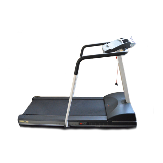
9.25, 9.25i Treadmill
9.25, 9.25i Treadmill
Warning: This service manual is for use by Precor trained service providers only.
If you are not a Precor Trained Servicer, you must not attempt to service any Precor Product;
Call your dealer for service.
This document contains information required to perform the majority of troubleshooting, and
replacement procedures required to repair and maintain this product.
This document contains general product information, software diagnostic procedures (when
available), preventative maintenance procedures, inspection and adjustment procedures,
troubleshooting procedures, replacement procedures and electrical block and wiring diagrams.
To move directly to a procedure, click the appropriate procedure in the bookmark section to the
left of this page. You may "drag" the separator bar between this page and the bookmark section
to change the size of the page being viewed.
© 2003 Precor Incorporated
Unauthorized Reproduction and Distribution Prohibited By Law
Page 1
Advertisement
Table of Contents
Troubleshooting

Related Manuals for Precor 9.25


Summary of Contents for Precor 9.25
- Page 1 9.25, 9.25i Treadmill Warning: This service manual is for use by Precor trained service providers only. If you are not a Precor Trained Servicer, you must not attempt to service any Precor Product; Call your dealer for service. This document contains information required to perform the majority of troubleshooting, and replacement procedures required to repair and maintain this product.
-
Page 2: Section One - Things You Should Know
Section Seven, Wiring and Block Diagrams. This section includes wiring and block diagrams 9.25 and 9.25i treadmill. General Information For the latest exploded view, part number and part pricing information, visit the Precor dealer website at “www.precor.com/Dealer”. Page 2... -
Page 3: Electronic Specifications
9.25, 9.25i Treadmill Technical Specifications Physical Specifications Length: 67 inches (170 cm) Width: 28.5 inches at handrails (71 cm) 25 inches at base (63.5 cm) Height: 44 inches Running surface: 51 inches by 17 inches (130 cm by 43 cm) Motor: 1.7 hp continuous duty... - Page 4 Plug the power cord into the wall outlet, then turn on the treadmill with the circuit breaker. The diagnostic program provide six different routines to aid it testing and trouble diagnosis. With the PRECOR M9.25 banner scrolling, press and hold ENTER until the software version number is displayed in the right display windows.
- Page 5 9.25, 9.25i Treadmill Diagram 2.1 - Display Housing, 9.25 Page 5...
- Page 6 For the purpose of accessing the various software routines, including the diagnostics program, the display housing keys are hypothetically numbered 1 to 7 from left to right. With the PRECOR M9.25i banner scrolling, press keys RESET,5,1,7,6,5,7,6,1, sequentially (See Diagram 2.2).
- Page 7 9.25, 9.25i Treadmill 11. The last routine is the circuit breaker trip test. This test checks the ability of the treadmill to trip the circuit breaker under software control. If the STOP key is pressed the trip signal will be sent to the circuit breaker and the circuit will trip, shutting off the treadmill. If you do not wish to trip the circuit breaker, press the ENTER key to exit the diagnostic program.
-
Page 8: Procedure 2.3 - Resetting All User Information
Procedure Plug the power cord into the wall outlet, then turn on the treadmill with the circuit breaker. With the PRECOR M9.25 or PRECOR M9.25i banner scrolling, press the INCLINE , INCLINE , SPEED , and SPEED keys simultaneously and hold them for approximately five seconds (or until zeros are displayed in the right display windows). - Page 9 Plug the power cord into the wall outlet, then turn on the treadmill with the circuit breaker. With the PRECOR M9.25 or PRECOR M9.25i banner scrolling, press any key. At the User ID prompt, select the User IDs to be reset using the SPEED...
-
Page 10: Procedure 2.5 - Displaying The Treadmill Odometer And Error Code Log
Procedure Plug the power cord into the wall outlet, then turn on the treadmill with the circuit breaker. With the PRECOR M9.25 banner scrolling, press the ENTER, SPEED and SPEED keys, simultaneously. Continue to hold the keys until the message TREADMILL ODOMETER scrolls across the left display window. - Page 11 9.25, 9.25i Treadmill Press ENTER. The error buffer is displayed and scrolls across the left display window (see Diagram 2.4). The most recent error condition will be displayed in position 1 and the oldest error will be displayed in position 5. When an error is added to a full log the new error will be inserted in position 1 and all other logs will be pushed down one position.
-
Page 12: Procedure 2.6 - Selecting United States Standard Or Metric Units
Press and hold STOP to return the PRECOR M9.45 banner. Note: On 9.25 treadmills, releasing the QUICK START key before the SPEED key when you perform the next step may cause the selected measurement standard to change to the alternate measurement standard. - Page 13 9.25, 9.25i Treadmill Use the SPEED or SPEED keys to select the alternate measurement standard. Press ENTER twice to return to the User ID prompt. Page 13...
-
Page 14: Procedure 2.7 - Determining Software Version Numbers
With the PRECOR M9.25 banner scrolling, press the ENTER key. On 9.25i treadmills, with the PRECOR M9.25 banner scrolling, press keys RESET,5,6,7,1, sequentially. On 9.25 treadmills, note the version number displayed in the right middle display window. The software version is not displayed in this procedure on 9.25i treadmulls. -
Page 15: Procedure 2.8 - Documenting Software Problems
If you isolated the problem to either the PROM, upper PCA, or lower PCA, include the information you recorded with the malfunctioning PROM or PCA when you ship it to Precor. When a problem occurs, record the following information: •... - Page 16 9.25, 9.25i Treadmill Section Three - Checking Treadmill Operation This section provides you with a quick method of checking treadmill operation. Check treadmill operation at the end of a maintenance procedure and when it is necessary to ensure that the treadmill is operating properly.
-
Page 17: Procedure 4.1 - Calibrating The Lift System
9.25, 9.25i Treadmill Procedure 4.1 - Calibrating the Lift System WARNING Always turn off the circuit breaker and unplug the treadmill before you remove the treadmill hood. Procedure Remove the hood as described in Procedure 5.1 of the Residential Treadmill Service Manual. - Page 18 9.25, 9.25i Treadmill Diagram 4.1 - Lift Motor Calibration Note: When you perform the next step, keep the white plastic nut in the same relative position to the drive screw. If necessary though, you may turn the drive screw 1/2 of a revolution.
-
Page 19: Procedure 5.1 - Troubleshooting The Keypad And Upper Pca
9.25, 9.25i Treadmill Procedure 5.1 - Troubleshooting the Keypad and Upper PCA If the function keys on the electronic console are unresponsive, the problem may be either the upper PCA or keypad. This troubleshooting procedure gives you the information you need to determine which of these components is malfunctioning. - Page 20 9.25, 9.25i Treadmill Table 5.1 - Voltage Test Points (Function Keys Not Pressed) Place the positive lead of the The voltmeter should read... voltmeter on... Pin 3 of J3 5 Vdc ± 500 mVdc Pin 4 of J3 5 Vdc ± 500 mVdc Pin 5 of J3 5 Vdc ±...
-
Page 21: Procedure 5.2 - Troubleshooting The Heart Rate System
Plug the power cord into the wall outlet, then turn on the treadmill with the ON/OFF switch. If necessary use conductive spray (Precor part number 37364-101) to ensure good contact between the chest strap transmitter and the user, put on the heart rate chest strap transmitter.Enter the diagnostics program per Procedure 2.1 or 2.2. - Page 22 9.25, 9.25i Treadmill Hold the Heart Rate Test Transmitter (Precor part number 20045-101) near the display housing. If the HEART RATE indicator on the electronic console blinks with the LED on the Smart Rate Test Generator... THEN... OTHERWISE... The chest strap assembly is bad.
-
Page 23: Procedure 5.3 - Troubleshooting The Lift System
9.25, 9.25i Treadmill Procedure 5.3 - Troubleshooting the Lift System System Description The lift system is powered by a 120 Vac lift motor that uses two independent motors windings, one operates the motor in an upward direction and one operates the motor in a downward direction. - Page 24 9.25, 9.25i Treadmill Remove the P2 connector from the lower board. Using an ohmmeter, measure between terminals 1 and 3 of P2, between terminals 1 and 2 of P2 and between terminals 2 and 3 of P2. The measurements should be approximately 14.5Ω, 14.5Ω and 29Ω, respectively. If any of the measurements are significantly low, replace the lift motor.
-
Page 25: Procedure 5.4 - Troubleshooting The External A.c. Power Source
Procedure 5.4 - Troubleshooting the External A.C. Power Source It is extremely important that any Precor treadmill be connected to and operated on a dedicated 20 amp A.C. circuit. A 20 amp dedicated circuit is defined as: a circuit fed by a 20 amp circuit breaker that feeds a single load. - Page 26 9.25, 9.25i Treadmill The circuit breaker correctly feeds a single A.C. outlet but the neutral is common between several A.C. outlets. The common neutral lead must be removed from treadmill’s A.C. outlet and a new neutral lead from the treadmill’s A.C. outlet to the A.C. neutral distribution bar must be added.
-
Page 27: Procedure 6.1 - Replacing The Fan
9.25, 9.25i Treadmill Procedure 6.1 - Replacing the Fan WARNING Always turn off the circuit breaker and unplug the treadmill before you remove the treadmill hood. Removing and Replacing the Fan Remove the hood. Remove the fan from the motor shaft. -
Page 28: Procedure 6.2 - Replacing The Speed Sensor
9.25, 9.25i Treadmill Procedure 6.2 - Replacing the Speed Sensor WARNING Always turn off the circuit breaker and unplug the treadmill before you remove the treadmill hood. Removing the Speed Sensor Remove the hood. Disconnect the speed sensor cable from the lower PCA. -
Page 29: Procedure 6.3 - Replacing The Lift Platform
9.25, 9.25i Treadmill Procedure 6.3 - Replacing the Lift Platform WARNING Always turn off the circuit breaker and unplug the treadmill before you remove the treadmill hood. Removing the Lift Platform Remove the hood. Place the treadmill on its left side. -
Page 30: Procedure 6.4 - Replacing The Lift Motor
9.25, 9.25i Treadmill Procedure 6.4 - Replacing the Lift Motor WARNING Always turn off the circuit breaker and unplug the treadmill before you remove the treadmill hood. Removing the Lift Motor Remove the hood. Disconnect the lift motor wiring assembly from the lower PCA. -
Page 31: Procedure 6.5 - Replacing The Prom
9.25, 9.25i Treadmill Procedure 6.5 - Replacing the PROM Anti-static kits (part number 20024-101) can be ordered from Precor. The PROM and the associated printed circuit assembly (PCA) are static sensitive. Anti- static devices must be used and all anti-static precautions must be followed during this procedure. -
Page 32: Wiring Diagram 7.3 - 9.25, 9.25I
9.25, 9.25i Treadmill Wiring Diagram 7.3 - 9.25, 9.25i Page 32... -
Page 33: Block Diagram 7.4 - 9.25, 9.25I
9.25, 9.25i Treadmill Block Diagram 7.4 - 9.25, 9.25i Page 33...
Need help?
Do you have a question about the 9.25 and is the answer not in the manual?
Questions and answers