
Related Manuals for EdilKamin POWER


Summary of Contents for EdilKamin POWER
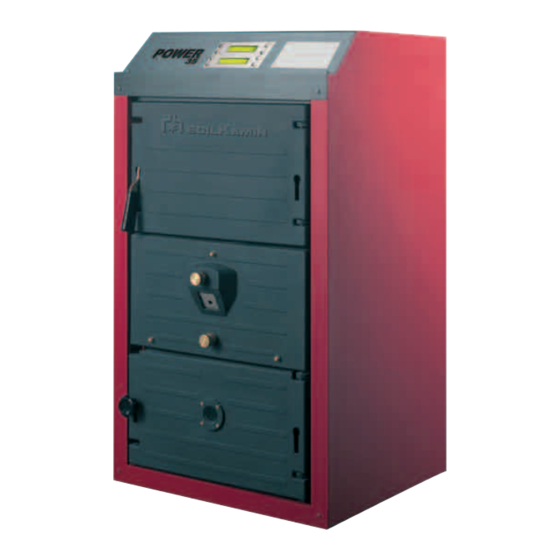
- Page 1 POWER Cast-iron wood gasification boiler Installation, user and maintenance manual The section for the user is at the end of the manual...
- Page 2 The appliance must be installed by qualified personnel in compliance with the technical standards and national and local legislation in force. In addition, the instructions on safety, installation, maintenance and operation provided in this manual must be observed. Instructions for disposing of the appliance (European Directive 2002/96/EC) The appliance, at the end of its working life, MUST BE DISPOSED OF SEPARATELY, as required by the legislation in force.
- Page 4 The Management WARRANTY The POWER appliances come with a SPECIFIC WARRANTY starting from the date this is validated by the Technical Service. The warranty does not cover the components subject to normal wear and tear, such as the refractory burner, the stainless steel duct and the ash container.
-
Page 5: Table Of Contents
CONTENTS SAFETY WARNINGS AND SAFETY RULES Pag. 6 PROHIBITED ACTIONS “ GENERAL INFORMATION ON USING WOOD FUEL Pag. 7 DESCRIPTION “ IDENTIFICATION “ LAYOUT OF THE MAIN COMPONENTS “ TECHNICAL SPECIFICATIONS “ 10 PROBES “ CONTROL PANEL “ WIRING DIAGRAMS “ 12 INSTALLATION RECEIVING THE PRODUCT... -
Page 6: Warnings And Safety Rules Pag
• In the event of water leaks, disconnect the appliance from the mains power supply, close the water supply and promptly notify the Technical Service or other professionally qualified personnel. -
Page 7: Information On Using Wood Fuel Pag
Combustion chamber Flue gas path DESCRIPTION The POWER boilers are hot water generators that operate by gasification of wood, with the combustion chamber kept at negative pressure and fan-assisted combustion with reverse flame. They feature a high quality and extremely thick EN GJL 200 cast-iron body. The large heat exchange surface, the fins in the flue gas path and the burner made from refractory material ensure exceptional resistance to corrosion and very high efficiency that remains constant over time (self-cleaning effect). -
Page 8: Identification
BOILER WATER CAPACITY CLASS INDEX OF PROTECTION POWER SUPPLY MAX POWER INPUT WARNING • If the rating plates or any other means of clearly identifying the product are defaced, removed or lost, proper installation and maintenance may be rendered difficult. -
Page 9: Layout Of The Main Components
LAYOUT OF THE MAIN COMPONENTS Control panel 12 Wood desiccation and gasification chamber Loading door 13 Mobile smoke plate Door handle/knob 14 Casing Combustion air distributor 15 Probe socket 16 By-pass Primary air register 17 Flue attachment Combustion air intake Secondary air register 18 Fan Combustion chamber door 19 Insulation... -
Page 10: Technical Specifications
°C Operating temperature (range) 70 ÷ 85 °C Minimum return temperature allowed °C Max operating pressure "PMS" Power supply 230 ~ 50 V ~ Hz Max power input Index of protection Class of the appliance 3 (**) n° < 1400 (*) < 2400 (*) mg/m Flue gas mass flow-rate 23,4 31,3... -
Page 11: Probes
- Boiler thermometer probe (TMC) Flue gas thermostat probe (TF) CONTROL PANEL Main switch TST Thermal safety thermostat with manual reset SAE Power indicator Boiler thermostat with heat removal function TMC Boiler thermometer Fan shutdown APC Activate loading procedure E/I Summer/winter selector switch... -
Page 12: Wiring Diagrams
230V~50Hz RESPONSIBILITY OF THE INSTALLER System pump Main system switch Main switch Boiler thermostat (70-85°C) Fuse (6,3 A - 250V T) Fan shutdown Power indicator light Timer(40 minutes) Loading door microswitch TST Thermal safety thermostat (110°C) Loading door relay Thermal safety thermostat Relay 1 contact Fan indicator light Load wood indicator light Minimum temperature relay CR2.1-CR2.4 Relay 2 contacts... - Page 13 CR2.1 CR2.2 CR2.3 CR2.4 System pump Main switch Fuse (6,3 A - 250V T) Boiler thermostat (70-85°C) Power indicator light Fan shutdown Loading door microswitch Timer(40 minutes) Loading door relay TST Thermal safety thermostat (110°C) Relay 1 contact Thermal safety thermostat Minimum temperature relay Fan indicator light CR2.1-CR2.4 Relay 2 contacts Load wood indicator light Minimum thermostat (50°C)
-
Page 14: Receiving The Product Pag
RECEIVING THE PRODUCT The POWER appliances are supplied in four boxes on a wooden pallet, protected by nylon wrapping and a cardboard 1 - Boiler body with outlet counterflange. Inside the desiccation/gasification chamber are the outlet and return stubs, the stainless steel duct. Attached to the boiler body is the document envelope (A),... -
Page 15: Handling
• DO NOT install the POWER appliances: - in inhabited rooms such as kitchens or living rooms, as special care is required and because, in some circumstances, smoke and odours may be released;... -
Page 16: New Installation Or Installation Replacing Another Appliance
Two reference parameters for normal water are: - pH=6÷8 - Total hardness ≤ 35°F. EDILKAMIN is not liable for any damage caused by the incorrect development of the flues. WATER CONNECTIONS The characteristics of the water fittings are shown in the... -
Page 17: Principle Diagram
CENTRAL HEATING Central heating flow outlet RETURN INLET Central heating return inlet IAF Cold water inlet Diagram 2: POWER boiler with energy accumulator to supply the systems CENTRAL HEATING FLOW OUTLET 1 Disconnect valve 2 Pumps 3 Non-return valves... - Page 18 Central heating flow outlet RETURN INLET Central heating return inlet IAF Cold water inlet Diagram 4: POWER boiler, combined with a DHW storage cylinder, with energy accumulator to supply the systems CENTRAL HEATING FLOW OUTLET 1 Disconnect valve 2 Pumps...
-
Page 19: Flue Gas Outlet And Combustion Air Intake
FLUE GAS OUTLET AND COMBUSTION AIR INTAKE The flues must be made in compliance with the standards and the legislation in force, using pipes that are rigid, resistant to high temperature, condensate and mechanical stress, and that are airtight. Ø 150 WARNINGS •... -
Page 20: Changing The Direction Of Opening
CHANGING THE DIRECTION OF OPENING The doors on the desiccation and gasification chamber and on the combustion chamber can be opened in either direction. In the factory they are fitted to open to the right, however, when required, this can be changed, as follows: Combustion air distributor - Unscrew the three nuts (1) and remove the distributor (2), handling it with care so as to avoid damaging the components installed. - Page 21 - Insert the pins (2) in the holes to secure the door (1) to the hinge (3). Door on the combustion chamber - Unscrew the locking knob (7) and open the door (8). - Remove the pins (9) that fasten the door to the hinge (10). - Remove the hinge (10) and the knob catch (11) and fit them on the other side. IMPORTANT: - The hinge (10) must always have the stop (A) at the top - The handle catch (11) must be turned over so that the shaped edge (B) is always facing the outside. - Thoroughly tighten the locking screws (12). - Insert the pins (9) in the holes to secure the door to the hinge (10). - Replace the combustion air distributor (2) and fasten it with the three nuts (1).
-
Page 22: Assembling The Microswitch
ASSEMBLING THE MICROSWITCH - Remove the microswitch (1), complete with cable, from the control panel packaging and fit it to the combustion air distributor, on the side with the handle for opening the desiccation and gasification chamber door. - Close the door and make sure that the microswitch contact is activated. -
Page 23: Assembling The Casing And The Control Panel
ASSEMBLING THE CASING AND THE CONTROL PANEL - Remove the panels making up the casing, the fastening brackets and the insulation for the boiler body from the packaging - Apply the insulation (1) around the boiler body - Prepare the microswitch cable for connection to the control panel - Fasten the support brackets (2) to the side panels (3) - Insert the boiler body studs in the front holes on the side panels (3) - Fasten together the brackets (2) on the side panels and the brackets (4) on the smokebox, using the screws (5) - Page 24 - Fasten the front panel (5) to the side panels (2) using the 6 screws supplied with the casing - Open the control panel by unscrewing the 3 locking screws (6). - Fasten the bottom part (7) of the control panel to the front panel (5) using the 4 screws supplied - Insert the thermal safety (TST), minimum (TM) and boiler (TC) thermostat and the boiler thermometer (TMC) bulbs in the probe socket (8), inserting them through the guide rings located on the side panels - Insert the flue gas thermostat bulb in the socket (9) fitted on the smokebox. - Insert the fan connector and fasten it to the slot (10) on the side panel.
-
Page 25: Electrical Connections
ELECTRICAL CONNECTIONS The POWER appliances require connection to the terminal block (M), as illustrated in the figures below; these connections must be made by the installer or other professionally qualified personnel. To access the terminal block, remove the front panel (1) from its housing. - Page 26 • DO NOT use the water pipes to earth the appliance. (*) EDILKAMIN is not liable for any damage due to the failure to earth the appliance and to observe the information provided on the wiring diagrams. Once the electrical connections are complete: - Fit the front panel and cover on the control panel and lock it with the screws that were removed previously.
-
Page 27: Filling And Emptying The System
FILLING AND EMPTYING THE SYSTEM Before starting the system filling and emptying operations, move the main system switch (IG) and the main switch (Ip) on the control panel to the “off” position. FILLING - Check that any system drain cocks (1) are closed. CENTRAL HEATING FLOW OUTLET - Open the on-off devices (2) of the system water and in the... -
Page 28: Commissioning
COMMISSIONING PRELIMINARY CHECKS Before commissioning the appliance, check that: - The on-off devices in the water circuit are open - The water circuit has been vented. - The electrical connections have been completed correctly - The flues and combustion air intake openings have been developed correctly. - The primary air and secondary air registers are both set to notch 2. - Page 29 - Wait a few minutes, open the loading door and load the appliance. - Close the loading door (1). - Make sure the flame is visible through the window (5). - Set the boiler thermostat (TC) between Tmax and Tmin. The appliance will remain on until the set temperature is reached.
-
Page 30: Reaching Steady State
REACHING STEADY STATE When the boiler has started, the "reaching steady state" phase commences, during which the water temperature must reach the value set using TC within 40 minutes If this is not the case, the indicator light (SCL) comes on. The probable causes are: - insufficient fuel - insufficient timer setting - heat required higher than the output delivered. -
Page 31: Setting The Timer
SETTING THE TIMER The time limit is set using the timer (T1): - Move the main system switch (IG) and the main switch (Ip) on the control panel to the "OFF" position. - Open the control panel by unscrewing the 3 locking screws. -
Page 32: Control Devices On The Appliance
CONTROL DEVICES ON THE APPLIANCE The appliance is fitted with the following control devices: - Thermal safety thermostat with manual reset (110°C; 0/-6°C). - Boiler thermostat with heat removal function. This has two functions: - Control the water temperature in the boiler from 70°C (min.) to 85°C (Max). - Start the system pump or the storage cylinder pump, where featured, when the temperature in the boiler exceeds the set temperature by 10 °C. -
Page 33: Maintenance And Cleaning Pag
MAINTENANCE AND CLEANING Periodical maintenance is a legal requirement and is essential for the safety, efficiency and life of the appliance. This ensures the condition of the components subject to normal wear can be checked and the deposits removed from the areas that are inaccessible to the user. - Page 34 - Disconnect the fan connection cable (8) and remove the fan (9), in the reverse order to that described on page 22 - Remove the rear panel (10) - Remove the cleanout door (11) - Clean the fan and the walls of the boiler and the smokebox. - Remove the residues. Clean all removed components, then follow the above steps in the reverse order to refit them.
-
Page 35: Troubleshooting
TROUBLESHOOTING Problem Cause Corrective Action - Clean and check the tightness of the flue gas path - Flue gases are escaping into the air - Check that the loading and combustion chamber doors close correctly - Check the wiring There is a smell of fumes. - Check the correct position of the AV - Fan switch... -
Page 36: Igniting The Appliance And First Load Pag
IGNITING THE APPLIANCE AND FIRST LOAD The user of a wood-fired boiler must be aware that the igniting and loading the boiler for the first time is a normal procedure whose frequency depends on the way the appliance is operated. - Move the main system switch (IG) and the main switch (Ip) on the control panel to the “ON”... - Page 37 - Wait a few minutes, open the loading door and load the appliance. - Close the loading door (1). - Make sure the flame is visible through the window (6). - Set the boiler thermostat (TC) between Tmax and Tmin. The appliance will remain on until the set temperature is reached.
-
Page 38: Subsequent Loads
SUBSEQUENT LOADS The wood can be loaded before it runs out or alternatively when the “load wood” indicator light (SCL) comes on. WARNINGS • Before loading the wood wear protection garments to avoid possible burns or problems when handling the wood. - Page 39 If the coals are extinguished: - Press the “fan shutdown” switch (AV) and check that the green indicator light (SV) goes off - Place small pieces of paper and dry wood (3) on the bottom of the chamber (2) and ignite them. - Wait for them to ignite and then close the loading door (1) SF SV - Press the “fan shutdown” switch (AV) and check that the green indicator light (SV) comes on.
-
Page 40: Shutdown
SHUTDOWN TEMPORARY SHUTDOWN In the event of temporary absence over the weekend, brief trips, etc. and when the outside temperature is above ZERO, proceed as follows: - Move the main system switch (IG) and the main switch (Ip) on the control panel to the "OFF" position. - Remove the ash from the combustion chamber. -
Page 41: Maintenance
MAINTENANCE Periodical maintenance is a legal requirement and is essential for the safety, efficiency and life of the appliance. This ensures the condition of the components subject to normal wear can be checked and the deposits removed from the areas that are inaccessible to the user. It must be performed by qualified personnel at least once a year so as to clean the entire flue gas path: desiccation/ gasification chamber, combustion chamber, smokebox and flues. - Page 42 INTERNAL CLEANING - Open the loading door (1). - Make sure there are no hot coals underneath the ash - Clean the walls of the desiccation/gasification chamber, using suitable equipment and remove/vacuum up the residues - Open the combustion chamber door (2) - Make sure there are no hot coals underneath the ash - Remove and empty the ash container (3) - Clean the inside parts and remove/vacuum up the residues...
-
Page 43: Troubleshooting
TROUBLESHOOTING Problem Cause Corrective Action - Check that the loading and combustion - Fumes are escaping into the air chamber doors close correctly - Check the correct position of the AV There is a smell of fumes - Fan always off switch - Follow the procedure described in - Ignition and/or loading of the boiler this manual - Rearrange the wood in the desiccation... -
Page 44: Useful References
USEFUL REFERENCES APPLIANCE Reseller: Installer: ......................................................Name Name ..........................................................Address Address ......................................................Phone Phone ......................................................... CHIMNEY SWEEP Name Name ..........................................................Address Address ......................................................Phone Phone .......................................................... Date Type of service - 44... -
Page 45: Notes
FUEL Supplier: Supplier: ......................................................Name Name ..........................................................Address Address ......................................................Phone Phone ........................................................Date Quantity supplied Date Quantity supplied Date Quantity supplied Date Quantity supplied NOTES - 45... - Page 46 NOTES - 46...
- Page 48 EDILKAMIN S.p.A. 20020 Lainate (MI) • via Mascagni, 7 tel. +39 02.937.62.1 • fax +39 02.937.62.400 mail@edilkamin.com • www.edilkamin.com EDILKAMIN is dedicated to the continuous improvement of all its products. The appearance, dimensions and technical specifications of equipment, accessories and appliances may therefore be subject change.
Need help?
Do you have a question about the POWER and is the answer not in the manual?
Questions and answers