Table of Contents
Advertisement
Quick Links
Advertisement
Table of Contents

Related Manuals for CHIEF Thinstall TA500

Summary of Contents for CHIEF Thinstall TA500
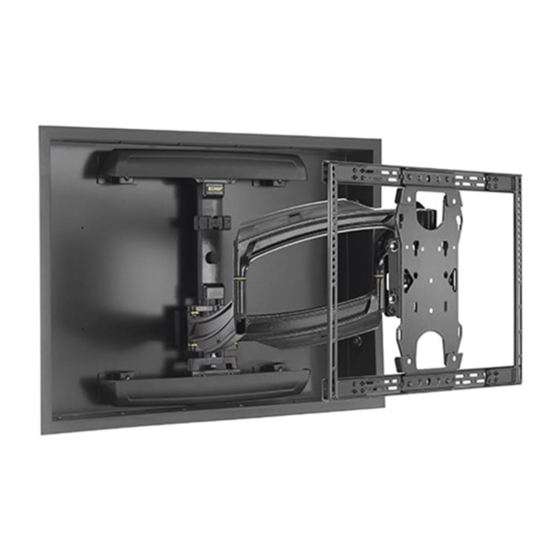
- Page 1 I N S T A L L A T I O N I N S T R U C T I O N S THINSTALL™ IN-WALL ENCLOSURE Spanish Product Description German Product Description Portuguese Product Description Italian Product Description Dutch Product Description French Product Description TA500...
-
Page 2: Important Safety Instructions
Do not use this product outdoors. no responsibility for accuracy, completeness or sufficiency of the information contained in this document. NOTES: Chief® is a trademark of Milestone AV Technologies. • SUITABLE FOR USE IN OTHER All rights reserved. ENVIRONMENTAL AIR SPACE IN ACCORDANCE WITH SECTION 300.22, (C) - Page 3 Installation Instructions TA500 DIMENSIONS STEEL CITY CY 1/2, OR DIMENSIONS: INCHES [MILLIMETERS] LEGEND Tighten Fastener Pencil Mark Apretar elemento de fijación Marcar con lápiz Befestigungsteil festziehen Stiftmarkierung Apertar fixador Marcar com lápis Serrare il fissaggio Segno a matita Bevestiging vastdraaien...
-
Page 4: Tools Required For Installation
TA500 Installation Instructions TOOLS REQUIRED FOR INSTALLATION 3/16” PARTS Grounding screw and washer installed at factory Earthing symbol IEC 60417 No. 5019 affixed adjacent to grounding terminal. B (4) [Mounting spacers] A (1) [TA500] C (12) E (6) M7 x 40mm 08 x 1/2”... - Page 5 IMPORTANT ! : The TA500 is designed for in-wall installation. installation spanning a minimum of three wood studs, 16" on center. Installation of TA500 in a wood stud wall will require additional framing to be added for support. WARNING: STRUCTURAL FAILURE HAZARD! FAILURE...
- Page 6 Drill four 3/16” diameter pilot holes in studs at side mounting holes. (See Figure 4) Attach the TA500 (A) to side studs using four M7 x 50mm Allen head connector screws (D) and mounting spacers (B) using an M4 Allen head drill bit (F). (See Figure 4)
- Page 7 Allen head drill bit (F). (See Figure 5) install any other wall mounts with the TA500! Use eight 5/16-18 x 1/2” button head cap screws (M) to attach four attachment brackets (N) to the TA500 (A). (See x 12 Figure 7) and (See Figure 8) IMPORTANT ! : Bracket orientation is different depending on mount being installed.
- Page 8 TA500 Installation Instructions Tighten two screws (M) to secure upper wall plate to upper attachment brackets. (TS525TU) Slide TS325TU/TS525TU assembly onto upper wall plate of TS325TU/TS525TU. (See Figure 10) (N) x 4 (M) x 8 TS325TU assembly shown Figure 8 Figure 10 Use two 5/16-18 x 1/2”...
- Page 9 (K) x 16 Figure 13 Cable Management Attach all cables to display. If necessary, use cable tie mounts (H) and cable ties (J) to secure cables within TA500. Figure 12 12. Complete TS325TU/TS525TU installation following TS325TU/TS525TU installation instructions. Trim Kit (Optional) Remove paper covering adhesive and affix three tape squares (K) to inside lower flange of each trim piece (G).
- Page 10 TA500 Installation Instructions...
- Page 11 Installation Instructions TA500...
- Page 12 A 6436 City West Parkway, Eden Prairie, MN 55344 P 800.582.6480 / 952.225.6000 F 877.894.6918 / 952.894.6918 Europe A Franklinstraat 14, 6003 DK Weert, Netherlands Chief Manufacturing, a products division P +31 (0) 495 580 852 of Milestone AV Technologies F +31 (0) 495 580 845 Asia Pacific A Office No.
Need help?
Do you have a question about the Thinstall TA500 and is the answer not in the manual?
Questions and answers