Carrier PGAPAXX1625 Installation Instructions Manual

Carrier PGAPAXX1625 Installation Instructions Manual

Germicidal air purifier

Advertisement

PGAP
NOTE: Read the entire instruction manual before starting the
install.

TABLE OF CONTENTS

. . . . . . . . . . . . . . . . . . . . . . . . . . . . . . . . . . .
. . . . . . . . . . . . . . . . . . . . . . . . . . . . . . . . . . .
. . . . . . . . . . . . . . . . . . . . . . . . . . . . . . . . . . . .
. . . . . . . . . . . . . . . . . . . . . . . . . . . . . . . . . . .
. . . . . . . . . . . . . . . . . . . . . . . . . . . . . .

INTRODUCTION

Congratulations for selecting the Air Purifier for your home
comfort system! The Air Purifier is proven to remove and kill
airborne germs and allergens, including viruses and bacteria. The
Air Purifier is a cornerstone of Healthy Home Solutions for
providing healthier, cleaner air in your home.

HOW IT WORKS

The Air Purifier provides extremely high filtration performance
while killing captured contaminants, including viruses and
bacteria. The Air Purifier treats the entire air- -stream through a state
of the art, three- -stage process.
In stage one, the particles are electrically charged by a
precision- -point ionization array as they enter the Air Purifier.
In stage two, the charged particles are electrically attracted to the air
purification cartridge, which is located within an electric field.
In stage three, captured particles are killed by electrical current
flow and ion bombardment.
The Air Purifier is Listed to applicable UL Standards and
requirements by Underwriters Laboratories Inc.
Ce purificateur d'air est conforme aux normes applicables dites
'UL', de Underwriters Laboratories Inc.
Installation Instructions
PAGE
. . . . . . . . . . . . . . . . . . . . . . . . .
. . . . . . . . . . . . . . . . . . . .
. . . . . . . . . . . . . . . . . . . . . . . .
. . . . . . . . . . . . . . . . . . . . . . .
Germicidal Air Purifier
Sizes 1620, 1625, 2020, 2025, 2420
1
1
1
2
3
9
10
11
12

SAFETY CONSIDERATIONS

Improper installation, adjustment, alteration, service, maintenance,
or use can cause explosion, fire, electrical shock, or other
conditions which may cause death, personal injury or property
damage. Consult a qualified installer, service agency or your
distributor or branch for information or assistance. The qualified
installer or agency must use factory- -authorized kits or accessories
when modifying this product. Refer to the individual instructions
packaged with the kits or accessories when installing.
Follow all safety codes. Wear safety glasses, protective clothing,
and work gloves. Have a fire extinguisher available. Read these
instructions thoroughly and follow all warnings and cautions
included in literature and attached to the unit. Consult local
building codes and the current edition of the National Electrical
Code (NEC) NFPA 70.
In Canada, refer to the current editions of the Canadian Electrical
Code CSA C22.1.
Recognize safety information. When you see this symbol
the unit and in instructions or manuals, be alert to the potential for
personal injury. Understand the signal words DANGER,
WARNING, and CAUTION. These words are used with the
safety- -alert symbol. DANGER identifies the most serious hazards,
which will result in severe personal injury or death. WARNING
signifies hazards, which could result in personal injury or death.
CAUTION is used to identify unsafe practices, which may result
in minor personal injury or product and property damage. NOTE
is used to highlight suggestions which will result in enhanced
installation, reliability, or operation.
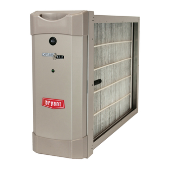
Fig. 1 - - PGAP Unit
A11332
on

Advertisement

Table of Contents
loading
Need help?

Need help?

Do you have a question about the PGAPAXX1625 and is the answer not in the manual?

Questions and answers

Summary of Contents for Carrier PGAPAXX1625

  • Page 1: Table Of Contents

    PGAP Germicidal Air Purifier Sizes 1620, 1625, 2020, 2025, 2420 Installation Instructions NOTE: Read the entire instruction manual before starting the install. TABLE OF CONTENTS PAGE INTRODUCTION ........HOW IT WORKS .
  • Page 2: Application Considerations

    PGAPAXX2420 include in-line fuses necessary for installation upstream of both the furnace and the air conditioning evaporator with fan coil air handlers. Air Purifier models PGAPAXX1625 and coil. This will help keep the furnace and evaporator coil clean and PGAPAXX2025 do not include in-line fuses as they are designed prevent condensation from forming within the Air Purifier.
  • Page 3: Installation

    INSTALLATION Identify Mounting Location 1. Identify a mounting orientation for the Air Purifier in the Check Air Purifier Components return air duct (see Figures 3 and 4). CAUTION IMPORTANT: 2. Ensure airflow direction through the Air Purifier matches the arrows on the face of the Air Purifier cart- CUT HAZARD ridge and those on the label on the front of the cabinet.
  • Page 4 NOTE: Mounting on this side requires the cabinet to be rotated 180° for correct air flow. This places the hinged end the door at the top of the cabinet and the handle/latch at the bottom. Air Flow Air Flow Air Flow A ir F lo w A11333 Fig.
  • Page 5 Side Mount Top Mount Bottom Mount A11368 Fig. 5 - - Mounting Air Purifier Cabinet Mount Cabinet WARNING ELECTRICAL SHOCK HAZARD Failure to follow this warning could result in personal injury or death. Before installing or servicing system, always turn off main power to system.
  • Page 6 5. Position the cabinet between the furnace and return air duct (see Figures 3, 4, and 5). A transition duct may be required. On some furnaces, one or more screws may interfere with the ease of removal of the purifier door. In this case, replace the interfering screw(s) with pop rivet(s).
  • Page 7 For the wiring in the furnace and fan coil wiring Fig. 12, provide power only when the furnace blower is operating. compartments Air Purifier models PGAPAXX1625 and PGAPAXX2025 are The incoming power supply wiring and connections for the air designed to be powered from the electronic air cleaner (EAC) purifier should be routed away from the output duct of the furnace terminals on a furnace electronic control.
  • Page 8 A12250 Fig. 13 - - Fan Coil Schematic A12251 Fig. 14 - - In- -line Fuse Installation Illustration For mounting to fan coil air handlers: CAUTION 1. Route the power conduit from the purifier to a knockout on the fan coil air handler that provides access to the incoming UNIT COMPONENT DAMAGE HAZARD power wiring compartment.
  • Page 9: Start- -Up And Operation

    1. Install the Filter Enhancement Module (FEM) into the cab- Carrier or Bryant logo into place with the text in upright po- inet, insuring that FEM is held firmly in place by the reten- sition.
  • Page 10: Maintenance

    5. This green indicator light will illuminate when the Air Puri- PURIFIER MODEL REPLACEMENT MEDIA CARTRIDGE fier door is installed, the power switch is in the ON position PGAPAXX1625 PGAPXCAR1625 AND the furnace blower is running. If a flow sensor (model PGAPAXX2025...
  • Page 11: Troubleshooting

    1. Turn the Air Purifier switch to the off position. 7. Turn the Air Purifier switch to the on position. 2. Remove the Air Purifier door. 8. Turn heating and cooling system power on. TROUBLESHOOTING 3. Slide out the Filter Enhancement Module (FEM). 4.
  • Page 12: Error And Status Codes

    ERROR AND STATUS CODES The error codes and status codes are shown in the following tables. NOTE: The green indicator light on door cover shown in Fig. 19, Power Indication (Green LED). Table 1 – Operating Status Codes INDICATOR LIGHT CODE EXPLANATION POSSIBLE CAUSE RECOMMENDED ACTION...
  • Page 13 Table 2 – Start- -Up Error Codes INDICATOR LIGHT CODE EXPLANATION POSSIBLE CAUSE RECOMMENDED ACTION No filter installed Place filter in air purifier. Install filter in correct orientation as indicated by airflow direction Filter installed incorrectly. arrows on cabinet and filter. Install a genuine air purifier Wrong type of filter installed replacement filter.
  • Page 14 Power Supply Flow Sensor KIT--- 160--- 000 (Included as standard with Models PGAPAXX1620, PGAPAXX2020, and PGAPAXX2420) Flow Sensor Bypass KIT--- 161--- 000 (Included as standard with Models PGAPAXX1625 and PGAPAXX2025) Front Screen KIT--- 170--- 000 KIT--- 171--- 000 KIT--- 172--- 000...
  • Page 16 Catalog No: IM---PGAP---01 Copyright 2012 CAC / BDP D 7310 W. Morris St. D Indianapolis, IN 46231 Edition Date: 09/12 Manufacturer reserves the right to change, at any time, specifications and designs without notice and without obligations. Replaces: NEW...

This manual is also suitable for:

Pgapaxx2025Pgapaxx1620Pgapaxx2020Pgapaxx2420

Table of Contents

Save PDF