
Related Manuals for Lake Lake LM Series


Summary of Contents for Lake Lake LM Series
- Page 1 Operation Manual Operation Manual Lake LM Series ® Digital Audio Processors Rev 1.3.5 Item: OM-LM...
-
Page 2: Important Safety Instructions
21. An experienced user shall always supervise this professional audio equipment, especially if inexperienced adults or minors are using the equipment. 22. The US National Differences clause 16.3 requires that network cables must be flame rated VW-1. Lake LM Series Operation Manual Rev 1.3.5... -
Page 3: Warning
▸ Reorient or relocate the antenna. ▸ Increase the separation between the equipment and receiver. Lake LM Series Operation Manual Rev 1.3.5... -
Page 4: User Responsibility
There is also a risk that the unit will malfunction since it is dependent on constant airflow from right to left. If the dust filter is not clean and the unit malfunctions, any resulting problems will not be covered by the warranty. Lake LM Series Operation Manual Rev 1.3.5... -
Page 5: Table Of Contents
Front Panel Interface ..........................16 Overview ............................16 Front Panel Key Lock .......................... 17 Power Button ..........................17 Meter Button ............................18 Menu Button ............................18 Exit Button ............................18 Dynamic Buttons, Controls and LEDs ....................18 Lake LM Series Operation Manual Rev 1.3.5... - Page 6 Digital Clock Configuration .........................57 Signal Processing Latency .........................59 10. Technical Specifications ........................61 11. Warranty and Support ..........................62 11.1 General ..............................62 11.2 International Warranties ........................62 11.3 Technical Assistance and Service ......................62 11.4 Trademarks ............................63 Lake LM Series Operation Manual Rev 1.3.5...
-
Page 7: Welcome
Welcome 2. Welcome Introduction Thank you for choosing the Lake LM Series of Digital Audio Processors. We are confident that you will be pleased with the performance, unique features, configuration flexibility, reliability, and long-term durability offered by this product. For fast installation and use of this product, your welcome package includes a printed copy of the LM Series Quick Start &... -
Page 8: Additional Documentation
If you intend to use the device as part of a networked system, or access features via the Lake Controller, please refer to the various supporting documents which can be located via these methods: ▸... -
Page 9: Installation
Cooling The Lake LM Series devices use a forced-air cooling system, with airflow from right to left. The dust filter on the air intake (right-side) should be regularly cleaned, especially after exposure to dusty environments, to ensure the maximum possible airflow through the unit. -
Page 10: Operating Voltage
The Iso-Float feature is activated by default, but may be disabled via the Lake Controller software, or via the front panel menu. Use correctly-shielded balanced audio input connections to minimise hum and interference. Please refer to section 7.1.5 for further information. -
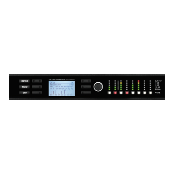
Page 11: Product Overview
LM Series devices are powered on and placed into standby mode using the left-most button, or via the Lake Controller. Standby mode is not equivalent to turning the device off at the mains power. All audio in and out of the processor is muted when in Standby mode. - Page 12 The function of these buttons change according to the currently selected view or menu. The left LED in the top button illuminates white to indicate the Frame is selected in the Lake Controller, or flashes white to indicate communication from the Lake Controller. If this button is pressed while in Home View, and with the Lake Controller on the Home page or the Modules Menu, the associated Module/s of the selected frame will be highlighted in the Controller (Module A in Contour Mode, or Modules A&B in Mesa...
- Page 13 The right bi-color LED in the top button illuminates red or yellow to indicate faults or warnings. If this button is pressed while in Home View, and with the Lake Controller on the Home page or the Modules Menu, the associated Module/s of the selected frame will be highlighted in the Controller (Module B in Contour Mode, or Modules C&D in Mesa Mode).
-
Page 14: Back Panel Overview
Analog outputs are provided via standard XLR3M connections. The outputs are electronically balanced and feature Lake Iso-Float circuitry; it is not recommended to use unbalanced connections. The output impedance is 50 ohms, providing a maximum output level of +21 dBu. Please refer to section 7.1 for further information. - Page 15 Ethernet control network ® which may include other Lake Processors and the Lake Controller software. Network connection permits full control of all functions along with real-time metering from a remote position. This device supports the Dante audio networking protocol, which allows transmission of multichannel, high-definition digital audio over the same Ethernet connection.
- Page 16 The IEC power cable provided includes a locking feature via a pin on the bottom of the connector; the connector can accept standard or locking IEC power cables. The power supply must be connected to AC mains using a power cable with a correctly wired plug for the country of operation. Lake LM Series Operation Manual Rev 1.3.5...
-
Page 17: Signal Flow And Lake Processing
Mesa Mode as described below). The blue sections represent Frame data, and the red sections represent Module data - please refer to the Lake Controller Operation Manual for further information. Important information regarding correct setting of the gain structure can be found in section 9.1. -
Page 18: Level Adjustments & Mute Points
In Contour Mode, a Module can be connected to Input Routers 1-4 providing all five stages of mute/connec- tivity functionality via the front panel interface or the Lake Controller; Input Routers 5-8 allow stage 1 input selection only (MUTE unavailable), along with stage 5 output ON/OFF routing connections (i.e. pass-thru). -
Page 19: Lake Processing And Control
5.4.1 Overview A Frame represents one physical Lake Processor (e.g. LM 26 or LM 44). In Contour Mode, a maximum of two Modules are contained within each Frame; these are referred to as Module A and Module B. The number of Modules shown in a given Frame is also dependent upon the signal processing configuration of that Frame. -
Page 20: Loudspeaker Processor (Contour Mode) Overview
Super Modules allow control of multiple Modules of the same type, distributed across multiple Frames, as a single entity within the Lake Controller software. A change made in the Super Module is replicated across all assigned Modules, resulting in improved efficiency in system configuration and a reduction of on-screen icons within the Lake Controller software. -
Page 21: Switching Between Contour And Mesa Mode
(i.e. the data shown in red in the signal flow diagrams in section 5.1). A Module file may be recalled into other Lake devices. It is not possible to store a Module File directly on the hardware device. -
Page 22: Front Panel Interface
Fault or warning conditions are indicated via the LEDs embedded in the dynamic function buttons; a simulta- neous description is shown adjacent to the button, on the LCD. Further information on faults and warnings is provided in section 6.7.2 and section 8.1. Lake LM Series Operation Manual Rev 1.3.5... -
Page 23: Front Panel Key Lock
Selecting a Module in the Lake Controller software via the device It is sometimes useful to identify which Module icon/s in the Lake Controller software are associated with a particular hardware Frame. To highlight the module in the Lake Controller software: 1. -
Page 24: Meter Button
In Menu Mode, pressing the EXIT button returns back one menu level. In Meter Mode, pressing EXIT returns the display to the Home View. Dynamic Buttons, Controls and LEDs Figure 6-3: LCD with Dynamic Buttons, Controls and LEDs Lake LM Series Operation Manual Rev 1.3.5... - Page 25 8.1. Additional faults and warnings are reported in the Event Log of the Lake Controller only. All faults and warnings recorded in the Event Log are listed in section 8.1 along with scenarios that may have arisen to cause them.
- Page 26 Turning the rotary encoder will adjust each parameter by the same increment. When in Meter Mode, the rotary encoder allows the user to change between the available meter views. Some menus permit parameters to be adjusted across multiple channels simultaneously by default. Lake LM Series Operation Manual Rev 1.3.5...
-
Page 27: Module I/O Mute Buttons And Led Meters
The embedded LED in each mute button confirms whether the associated Module input/s or output/s are muted (red), unmuted (white), associated input router is muted (pink), or unused (not illuminated) as shown in Figure 6-5. Lake LM Series Operation Manual Rev 1.3.5... - Page 28 Mixer. If all Input Routers used by an Input Mixer are muted the LED turns red to indicate a full mute; this type of mute cannot be unmuted from Home View. Input router mutes are accessed via the I/O Status View as described below, or via the Lake Controller Levels screen as described in the Lake Controller Operation Manual.
-
Page 29: Meter Mode
Mode. The quantity and position of the output mute buttons changes as shown in Figure 6-4 depending on whether the device is configured in Contour Mode (six outputs) or Mesa Mode (four outputs). Please refer to the Lake Controller Operation Manual for details of Module mute controls via the software. 6.8.2... - Page 30 1-4, page two displays input routers 5-8. In I/O Status View, the front panel mute button and metering LED’s change to represent the Input Router mute status an metering levels as described in 6.8. Lake LM Series Operation Manual Rev 1.3.5...
- Page 31 The faults and warnings LED is accompanied by text on the top-right side of the LCD. The LED illumi- nates red if any input is muted, or if another fault condition occurs; it illuminates yellow if a warning condition arises. Please refer to section 6.7.2 for further details. Lake LM Series Operation Manual Rev 1.3.5...
-
Page 32: Menu Mode
Changes are effected in real-time and a stored without further confirma- tion. Pressing EXIT returns to the previous menu level, automatically retaining any parameter changes. All parameters are also editable via the Lake Controller unless specified otherwise. - Page 33 Groups function in the Lake Controller. The Group total is the sum of the individual Module value plus any values for this parameter on all Groups to which the Module is assigned. Please refer to the Lake Controller Operation Manual for further information on Groups.
- Page 34 For frames where both Modules have four output channels or less, a detailed parameter screen as shown in Figure 6-14 is displayed. Where Module A has five output channels or more, the combined summary edit screen shown in Figure 6-15 is the only screen available. Lake LM Series Operation Manual Rev 1.3.5...
- Page 35 Module Delay adjustment follows the same logic as Module Gain. Please refer to section 6.10.2.2 for further information. Multiple delay values may be adjusted simultaneously in 0.1 ms increments, subject to defined level limits. Lake LM Series Operation Manual Rev 1.3.5...
- Page 36 A soft-knee or hard-knee corner may be applied to the RMS Limiter. A soft-knee corner gently increases limiting as the signal approaches the threshold; a hard-knee corner applies full limiting to any signal exceed- ing the threshold by any amount, but none to signals below the threshold. Lake LM Series Operation Manual Rev 1.3.5...
- Page 37 LimiterMax provides peak and RMS limiting features, referred to as MaxPeak and MaxRMS respectively. Full details regarding LimiterMax can be found in the Lake Controller Operation Manual. 6.10.3 I/O Config Submenu MENU > I/O CONFIG Figure 6-16: I/O Config Submenu This menu provides configuration options for input and output routing, along with settings for AES Termina- tion and Iso-Float as described in the following sections.
- Page 38 This is equivalent to the DISPLAY DETAILS option in the Lake Controller. Adjust a parameter by pressing the associated button, and then use the rotary encoder to change the value.
- Page 39 DA output per processor, then all terminations should be on. However, if the AES3 is daisy-chained, only terminate the last processor in the chain. 6.10.3.3 Iso-Float MENU > I/O CONFIG > ISO-FLOAT Figure 6-19: Iso-Float Menu Lake LM Series Operation Manual Rev 1.3.5...
- Page 40 This section of the screen displays the selected audio source This section of the screen displays the selected output destination type This section of the screen displays the channels for the selected audio source Lake LM Series Operation Manual Rev 1.3.5...
- Page 41 Frame Info provides information about the device settings and configuration. All data in this front panel menu is read-only; some parameters are fixed, some can be changed only via the Lake Controller software. Lake LM Series Operation Manual Rev 1.3.5...
- Page 42 Front Panel Interface Frame Label The Frame Label as defined in the Lake Controller is displayed in this menu. It is also displayed at the top-left of the screen in Meter Mode, Home View. Serial Number (Serial No.) The printed serial number on the back panel of the device is also electronically embedded in the hardware, and therefore cannot be removed or altered if stolen.
- Page 43 When Latency Match is ON the LM Series device adds delay to match the overall processing delay of legacy Lake Contour Pro 26 and Mesa Quad EQ products. Please refer to the Lake Controller Operation Manual for further information.
- Page 44 GPI closed to open transition when the selected GPI is currently open is not executed until the next transi- tion to open. A change in GPI open/closed state occurring when the device is disconnected from power will be acknowledged and executed when power is reconnected. Lake LM Series Operation Manual Rev 1.3.5...
- Page 45 Two input options (GPI) and two output options (GPO) may be set at any one time. The default GPIO con- figuration is shown in Table 6-5. The current state (open/closed) is reported for all GPIO settings on the front panel and in the Lake Controller software. Lake LM Series Operation Manual Rev 1.3.5...
- Page 46 To adjust the front panel LCD & LED brightness, select this option then use the rotary encoder to change the value. 6.10.6 Frame Preset Menu MENU > FRAME PRST Figure 6-26: Frame Preset Menu Lake LM Series Operation Manual Rev 1.3.5...
- Page 47 To recall an existing Frame Preset, use the rotary encoder to select the required Preset then press the RECALL button to overwrite the current configuration. Frame Presets must initially be created in the Lake Controller, and stored as a Preset using the Lake Controller or the LM Series Preset Manager.
-
Page 48: Back Panel Interface
Six (LM 26) or four (LM 44) electronically-balanced analog outputs are provided via standard XLR3M connec- tions. OUTPUT OUTPUT OUTPUT OUTPUT OUTPUT OUTPUT INPUT INPUT Figure 7-3: Analog Output XLR Connections (LM 26) Lake LM Series Operation Manual Rev 1.3.5... - Page 49 Figure 7-6. COLD COLD SCRN SCRN Unbalanced Output Balanced Input (Typically phono) (XLR) Figure 7-6: Balanced to Unbalanced Analog Wiring and Pin Out Lake LM Series Operation Manual Rev 1.3.5...
-
Page 50: Aes3 Digital I/O
High-quality transformers and opto-isolators create a barrier between the device and possible grounding aberrations from the outside electrical environment. Iso-Float settings are adjustable via the front panel menu or the Lake Controller software. AES3 Digital I/O 7.2.1... -
Page 51: Rj45 Ethercon Network Connections
Figure 7-5 on page 43 shows the only possible method of wiring; there is no equivalent of an unbalanced connection in the digital domain. RJ45 etherCON Network Connections Two RJ45 etherCON style network connections are provided as shown in Figure 7-10. Lake LM Series Operation Manual Rev 1.3.5... - Page 52 When the device is connected to an active network, the yellow LINK LED illuminates above the connector in use. Data activity on the network is indicated by illumination of the green ACT LED. It is normal for the ACT LED to flicker either sporadically or continuously. Lake LM Series Operation Manual Rev 1.3.5...
-
Page 53: Gpio Connection
Table 7-3: GPIO Pinout Wiring Reference GPIO configuration is available via the front panel interface or via the Lake Controller software. Please refer to section 6.10.4.4 of this manual for additional information on adjustment via the front panel, and refer to the Lake Controller Operation Manual for information on adjusting via software interface. -
Page 54: Universal Power Supply Connection
IEC power cables. The power supply must be connected to AC mains using an IEC power cable with a correctly wired and molded plug for the country of operation. Lake LM Series Operation Manual Rev 1.3.5... -
Page 55: Appendix
AES Clock Warning aligned. Verify digital input configuration to ensure all clock settings SLIPPING Slipping match. The device is no longer able to communicate with the Lake Control- CTRL OFFLINE Warning ler. Check network connectivity. NAME Dante device There are multiple devices with identical Dante device names;... -
Page 56: Maintenance
Router 3: Priority 1 = Dante (Ch.3), Priority 2 = Empty, Priority 3 = AES (Ch.3), Priority 4 = Empty Router 4: Priority 1 = Dante (Ch.4), Priority 2 = Empty, Priority 3 = AES (Ch.4), Priority 4 = Empty Lake LM Series Operation Manual Rev 1.3.5... -
Page 57: Glossary Of Terms, Acronyms And Abbreviations
The Ethernet ports can operate with either straight or crossed network cables. This ability to connect correctly with either type is Auto-Uplink termed auto-uplinking. Some of the configurations possible in the Lake processing system Modules result in a single audio processing channel being created in Auxiliary Output addition to a crossover. This is termed an Auxiliary output. - Page 58 (nearly as good, without full electrical isolation, but a great deal cheaper). The details of any fault or warning conditions which arise in the device during operation are recorded in a data file created by the Lake Event Log Controller software called the Event Log.
- Page 59 Term Description This term refers to older Lake audio equipment which may form part of an audio system (i.e. Lake Contour Pro 26, Lake Mesa Quad EQ Legacy Lake Device and the Dolby Lake Processor). The Lake Controller has the capability to control all Lake legacy products.
- Page 60 A device used to connect a computer to an Ethernet network without cables; a radio transmitter/receiver for data. Wireless Network An Ethernet network where some or all cabled connections are replaced by wireless links. Table 8-2: Glossary of Terms, Acronyms and Abbreviations Lake LM Series Operation Manual Rev 1.3.5...
-
Page 61: Application Guide
Input Mixer gains can remain at 0.00 dB for most configurations; if only one input channel is used per Module, the other can be set to -INF. To adjust, navigate to I/O CONFIG and tap the Input Mixer blocks for the Module in the Lake Controller. Please refer to the Lake Controller Operation Manual for further details. -
Page 62: Gain / Level Optimization
1. Factory Gain is set by the system designer and can be hidden within the Module file. The Factory Gain parameter is only accessible when the Module is unlocked and the Lake Controller is in Designer Mode. Adjust via MODULES > LEVELS > METER OPTIONS > ADJUST FACTORY. - Page 63 Distribution amplifiers that offer re-clocking often make the feature optional as using re-clocking can intro- duce small additional amounts of latency, so should not be used unless necessary. Lake LM Series Operation Manual Rev 1.3.5...
-
Page 64: Digital Clock Configuration
There are two separate digital clocks which can generate various independent internal sample rates, or can sync to an incoming AES3 signal. Figure 9-1 shows the various sample rates and options available. Figure 9-1: Digital Clocking System Lake LM Series Operation Manual Rev 1.3.5... - Page 65 Application Guide In Figure 9-1, each circled C represents a choice point. A choice point is a user‐interface control that can be configured using the Lake Controller software. Please refer to the Lake Controller Operation Manual for further information. Figure 9-1 indicates internally generated clocks with base-rate multiples of 44.1 kHz or 48 kHz.
-
Page 66: Signal Processing Latency
The front panel I/O Status View indicates if that device is selected as Dante Clock Master. Confirmation of Dante Master / Slave status is also displayed in the Lake Controller. The Dante Preferred Master setting can be set from the Lake Controller I/O Configuration screen, or via the Dante Controller. - Page 67 Analog 0.395 0.406 48 kHz sync 48 kHz sync 0.545 0.545 96 kHz sync Analog 0.138 0.150 96 kHz sync 96 kHz sync 0.059 0.059 Table 9-2: Latency for Common I/O Configurations (Pass-thru) Lake LM Series Operation Manual Rev 1.3.5...
-
Page 68: Technical Specifications
GPIO DB-9 Power Detachable locking 3-pin IEC Control and monitoring interface Via Ethernet for Lake Controller software, or DLM (the 3rd party protocol) Dimensions (W/H/D) 483 mm (19"), 44 mm (1 U), 290 mm (11.5") Weight 5 kg (11 lbs) -
Page 69: Warranty And Support
Lake dealer. If the product fails to perform as specified during the warranty period, Lake will undertake to repair, or at its option, replace this product at no charge to its owner, provided the unit is returned undamaged, shipping prepaid, to an authorized service facility or to the factory. -
Page 70: Trademarks
Warranty and Support 11.3.2 Factory Service In the event a Lake product requires factory service, you may contact Lake’s service department for return instructions and a Return Authorization number. Please note for product return: Use the original packing. Include a copy of the sales receipt, your name, return address, phone and fax number, email address and description of the defect. - Page 71 Operation Manual I N T E R N A T I O N A L C O N T A C T ► I N F O @ L A K E P R O C E S S I N G . C O M U S & C A N A D A C O N T A C T ► I N F O @ T C G - A M E R I C A S . C O M w w w .
Need help?
Do you have a question about the Lake LM Series and is the answer not in the manual?
Questions and answers