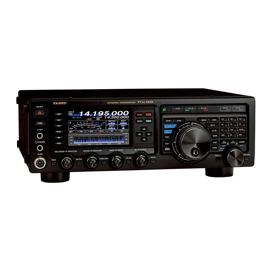
Yaesu FT DX 1200 Operation Manual
Hf/50 mhz transceiver
Hide thumbs
Also See for FT DX 1200:
- Operating manual (140 pages) ,
- Operating manual (37 pages) ,
- Operating manual (15 pages)
Table of Contents
Advertisement
Quick Links
HF/50 MH
T
Z
RANSCEIVER
FT
1200
DX
O
M
PERATING
ANUAL
YAESU MUSEN CO., LTD.
Tennozu Parkside Building
2-5-8 Higashi-Shinagawa, Shinagawa-ku, Tokyo 140-0002 Japan
YAESU USA
6125 Phyllis Drive, Cypress, CA 90630, U.S.A.
YAESU UK
Unit 12, Sun Valley Business Park, Winnall Close
Winchester, Hampshire, SO23 0LB, U.K.
YAESU HK
Unit 2002, 20/F, 9 Chong Yip Street,
Kwun Tong, Kowloon, Hong Kong
Advertisement
Table of Contents

Related Manuals for Yaesu FT DX 1200


Summary of Contents for Yaesu FT DX 1200
- Page 1 HF/50 MH RANSCEIVER 1200 PERATING ANUAL YAESU MUSEN CO., LTD. Tennozu Parkside Building 2-5-8 Higashi-Shinagawa, Shinagawa-ku, Tokyo 140-0002 Japan YAESU USA 6125 Phyllis Drive, Cypress, CA 90630, U.S.A. YAESU UK Unit 12, Sun Valley Business Park, Winnall Close Winchester, Hampshire, SO23 0LB, U.K.
- Page 2 . . . BOUT ANUAL The FT 1200 is a leading-edge transceiver with a number of new and exciting features, some of which may be unfa- miliar to you n order to gain the most en oyment and o erating ef ciency from your FT 1200, we recommend that you read this manual in its entirety, and keep it handy for reference as you explore the many capabilities of your new transceiver.
- Page 3 Congratulations on the purchase of your Yaesu amateur Fre uency setup is straightforward on the FT 1200. transceiver f this is your rst rig, or if Yaesu e uipment nter fre uency directly for F - . eparate keys are is already the backbone of your station, rest assured available for band selection.
-
Page 4: Table Of Contents
ABLE OF ONTENTS ) ne-Touch IF Filter Selection . General Description ............. 1 TCH Filter peration Table of Contents ............2 odes ) ..6 SSB CW TTY Accessories & Options ..........4 F ) peration ....7 upplied ccessories ..........4 igital TCH Filter ) peration .... -
Page 5: Table Of Contents
ABLE OF ONTENTS Operation on Alaska Emergency Frequency: 5167.5 khz (U.S. Version Only) ......... 99 VFO and Memory Scanning ........100 VF Scanning ............100 emory Scan ............101 PMS (Programmable Memory Scanning) ..... 102 RTTY ( Radio Teletype ) Operation ......103 with ptional FFT nit ) ..... -
Page 6: Upplied Ccessories
& O CCESSORIES PTIONS UPPLIED CCESSORIES Hand icrophone MH-31 1 pc 078 0001 C ower Cord 1 pc Spare Fuse 25A) 1 pc Q0000074 00 136 perating anual 1 pc Warranty Card 1 pc 12 00 O Page 4 PERATING ANUAL... -
Page 7: Vailable Ptions
& O CCESSORIES PTIONS VAILABLE PTIONS MD-200 Ultra-High-Fidelity esktop icrophone MD-100 esktop icrophone YH-77STA Lightweight Stereo Headphone emote Control eypad FH-2 VL-1000/VP-1000 Linear mpli er C ower Supply RF μTuning Kit A For 160 m Band RF μTuning Kit B For 80 40 m Bands RF μTuning Kit C For 30 0 m Bands... -
Page 8: Xtending The Front Feet
EFORE EGIN XTENDING THE RONT To elevate the front panel for easy viewing, the front left and right feet on the case bottom may be extended. ull the front legs outward from the bottom panel. otate the legs counter-clockwise to lock them in the extended position. -
Page 9: Esetting The Installation And Interconnections
EFORE EGIN DJUSTING THE LOCK Use the following procedure to adjust the clock shown at the middle right of the TFT display. ress and hold the [C.S] button until the clock digits [ BAND ] keys blink. nter the present time with the number keys [ BAND ] keys). - Page 10 NSTALLATION AND NTERCONNECTIONS NTENNA ONSIDERATIONS The FT 1200 is designed for use with any antenna system providing a 0 hm resistive impedance at the desired op- erating fre uency. While minor excursions from the 0- hm speci cation are of no conse uence, if the Standing Wave atio SW ) present at the ntenna jack is greater than 3 1, the transceiver s utomatic ntenna Tuner may not be able to reduce the impedance mismatch to an acceptable value.
- Page 11 NSTALLATION AND NTERCONNECTIONS ROUNDING The FT 1200 transceiver, like any other HF communications apparatus, re uires an effective ground system for maxi- mum electrical safety and best communications effectiveness. good ground system can contribute to station ef ciency in a number of ways It can minimi e the possibility of electrical shock to the operator.
- Page 12 NSTALLATION AND NTERCONNECTIONS ONNECTION OF NTENNA AND OWER ABLES lease follow the outline in the illustration regarding the proper connection of antenna coaxial cables, as well as the C power cable. The C power connector for the FT 1200 must only be connected to a C source providing 13.8 Volts C ), and capable of at least 3 mperes of current.
-
Page 13: Connection Of
NSTALLATION AND NTERCONNECTIONS ONNECTION OF ICROPHONE AND EADPHONE 12 00 O Page 11 PERATING ANUAL... -
Page 14: Interconnections
NSTALLATION AND NTERCONNECTIONS EYER OMPUTER RIVEN EYING NTERCONNECTIONS The FT 1200 includes many features for the CW operator. These functions will be detailed in the “ peration” section later. Besides the built-in lectronic eyer, two key jacks are provided, one on the front and one on the rear panel, for convenient connection to keying devices. - Page 15 NSTALLATION AND NTERCONNECTIONS VL-1000 L INEAR MPLIFIER NTERCONNECTIONS Be sure that both the FT 1200 and VL-1000 are turned off, and then follow the installation recommendations con- tained in the illustration. efer to the VL-1000 perating anual for details regarding ampli er operation. o not attempt to connect or disconnect coaxial cables when your hands are wet.
- Page 16 NSTALLATION AND NTERCONNECTIONS NTERFACING TO THER INEAR MPLIFIERS EXT ALC TX GND MPORTANT The T G UT pin pin ) of the LINEAR jack o not exceed the maximum voltage or current rat- is a transistor “open collector” circuit. It is capable of ings for the “T G UT”...
-
Page 17: Plug/Connector Pinout Diagrams
ONNECTOR INOUT IAGRAMS 12 00 O Page 15 PERATING ANUAL... -
Page 18: Front Panel Controls & Switches
& S RONT ANEL ONTROLS WITCHES [ POWER ] Switch When the utomatic ntenna Tuner is tuning itself, ress and hold in this switch for one second to turn a signal is being transmitted. Therefore, be certain the transceiver on. Similarly, press and hold in this that an antenna or dummy load is connected to the switch for one second to turn the transceiver off. - Page 19 & S RONT ANEL ONTROLS WITCHES PHONES Jack Because the roofing filter is in the first IF, the protection it provides against interference is uite 1 4-inch, 3-contact jack accepts either monaural or significant. When set to UT , the SSB band- stereo headphones with - or 3-contact plugs.
- Page 20 & S RONT ANEL ONTROLS WITCHES [ MIC/SPEED ] Knob [ PROC/CAR ] Knob PROC This knob adjusts the microphone input level for This knob adjusts the compression input) level non-processed) SSB transmission. of the transmitter F speech processor in the SSB The display will show the relative microphone gain mode.
- Page 21 & S RONT ANEL ONTROLS WITCHES [ NOTCH ] [ BK-IN ] Switch Switch ressing this button allows you to adjust the center This button turns the CW break-in capability on and fre uency of the IF otch lter using the [ NOTCH ] off.
- Page 22 & S RONT ANEL ONTROLS WITCHES [ SCOPE ] [ SELECT ] Switch Switch ress this button momentarily to switch between the This button is used to select the enu system. enu, the Scope, the Full TFT screen Scope, the ] Switch Scope F-FFT when the optional FFT unit is in-...
- Page 23 & S RONT ANEL ONTROLS WITCHES [ A B ] Switch [ NAR ] ( Narrow ) Switch ress this button momentarily to transfer the fre- This button is used to set the S digital) IF lters uency or memory channel data, from VF - to arrow bandwidth.
- Page 24 & S RONT ANEL ONTROLS WITCHES [ SPLIT ] Switch [ M A ] Switch ress this button to operate split fre uency between ressing this button momentarily, will display the VF - used for reception) and VF -B used for contents of the currently-selected memory channel transmission).
- Page 25 & S RONT ANEL ONTROLS WITCHES [ MODE ] Switch Main Tuning Dial Knob This button selects the operating mode. The selec- This large knob adjusts the operating fre uency of tions available are VF - . Clockwise rotation of this knob increases the fre uency.
- Page 26 & S RONT ANEL ONTROLS WITCHES [ BAND ] Keys [ TX CLAR ] Switch These keys allow one-touch selection of the desired ressing this button activates the T Clari er, to al- mateur band 1.8 H ). low offsetting the transmit fre uency temporarily. The keys may also be used for direct entry of a de- ress this button once more to return the transmit- sired operating fre uency during VF operation.
- Page 27 & S RONT ANEL ONTROLS WITCHES [ MHz/μT ] Switch [ MCH/GRP ] Switch ressing this button allows you to tune the VF fre- uency down or up in 1 H increments, using the ressing this button allows you to select a memory [ VFO-B/CLAR ] knob.
-
Page 28: Display Indications
ISPLAY NDICATIONS Tuning Offset Indicator TUNER This indicates the relative offset of the CW-TU This indicator appears when the internal utomatic , Clari er, etc. ntenna Tuner is activated. S/PO Meter n reception, this indicates the received signal This indicator appears when the automatic voice- strength from S-0 to S- 60dB. - Page 29 ISPLAY NDICATIONS PROC ( Processor): Clock This indicator enables the Speech rocessor for Indicates the current time. SSB transmission. djustment of the rocessor To set the clock level is accomplished via the [ PROC/CAR ] knob. 1. ress and hold the [ C.S ] button until the clock digits blink.
- Page 30 ISPLAY NDICATIONS LED Indicators RX Indicator Main Tuning Dial FAST/LOCK This indicator illuminates when the s uelch opens. Indicators FAST: TX Indicator This indicator appears when the ain Tuning ial This indicator illuminates during transmission. knob tuning rate is set to “fast”. Memory Mode RX/TX Indicators LOCK: Green (Left):...
-
Page 31: Rear Panel
ANEL ANT 1/2 Jacks ROT Jack Connect your main antenna s) here, using type- This covered 6-pin I I- I ack accepts a cable ) connectors and coaxial feed lines. The in- to connect to a Y SU G-800DXA -1000DXA/ ternal antenna tuner affects only the antenna s) con- -2800DXA ntenna otator listed models are cur- nected here, and only during transmission. - Page 32 ANEL REC Jack KEY Jack This 3. -mm, 3-contact jack provides low-level This 1 4-inch 3-contact jack accepts a CW key or key- receiver audio output for recording. It also outputs er paddle. two-contact plug cannot be used in this voice audio during transmission if the “MONI”...
- Page 33 FH-2 S PTIONAL WITCHES The optional emote Control eypad FH-2 can be used to control the optional VS-6 Voice emory capability for the modes the contest memory keyer for the CW mode and the text memory for the TTY T modes. Some speci c capabilities of the FH-2...
- Page 34 ASIC PERATION ECEIVING ON MATEUR ANDS Before turning on the main power, please verify the following items once more. Have you made all ground connections securely See page for details. o you have your antenna s) connected to the rear-panel ntenna jack s) See page 10 for details. Is your microphone and or key or paddle) connected See pages 11, 1 for details.
- Page 35 ASIC PERATION ECEIVING ON MATEUR ANDS Here is the typical start-up procedure for normal operation [ POWER ] Switch [ BAND ] Keys [ ANT ] Switch [ AF ] Knob [ MODE ] Button Main Tuning Dial Knob momentary presses of the [ 14 ] 1.
- Page 36 ASIC PERATION ECEIVING ON MATEUR ANDS though the actual tone that you hear is not chang- The tuning steps for the ain Tuning ial knob ing. are set, at the factory, to 10 H SSB, CW, TTY, mode, rotate the [ RF/ When operating on the F T ) and 100 H F ) per step.
- Page 37 ASIC PERATION ECEIVING ON MATEUR ANDS ( 5 MH 60-M AND ( U.S. PERATION ON ETER U.K. VERSION ONLY The recently-released 60-meter band is covered, in the FT 1200, by xed memory channels. These channels are set to USB or CW, and they appear between the “last” S channel “P9U”) and the rst “regular”...
- Page 38 ASIC PERATION ECEIVING ON MATEUR ANDS CLAR ( C LARIFIER PERATION The [ RX CLAR ] , [ TX CLAR ] , [ CLEAR ] buttons and [ VFO-B/CLAR ] knob are used to offset the receive fre uency, the transmit fre uency, or both, from their settings on the VF - fre uency. Four small numbers on the TFT isplay show the current Clari er offset.
- Page 39 ASIC PERATION ECEIVING ON MATEUR ANDS LOCK ain Tuning ial knob for VF - fre uency tuning) and the [ VFO-B/CLAR ] knob for You may lock the setting of the VF -B fre uency tuning during Split operation), to prevent accidental fre uency change. Main Tuning Dial Knob Lock [ CLEAR ( LOCK) ] Button ial knob, press the [ LOCK ]...
-
Page 40: Convenience Features
ONVENIENCE EATURES TACK PERATION The FT 1200 utili es a triple band-stack VF selection techni ue, that permits you to store up to three favorite fre- uencies and modes onto each band’s VF register. For example, you may store one fre uency each on 14 H CW, TTY, and USB, then recall these VF s by successive, momentary presses of the [ 14 ] H band button. -
Page 41: Scope
ONVENIENCE EATURES SCOPE This function displays a convenient spectrum scope for monitoring the band conditions. Both strong and weak signals can be displayed in an easy-to-understand manner on the TFT screen. This multifunctional scope takes into consid- eration the operator’s preference, by switching between the convenient C mode where the VF fre uency is constantly in the center of the screen for monitoring conditions on both sides of your operating fre uency), and the FI... -
Page 42: Center Mode
ONVENIENCE EATURES SCOPE CENTER mode FIX mode 1. Switch operation mode to “C mode”. 1. Switch the operation mode to “FI mode”. See “Switching between C odes” See “Switching between C odes” below for details on changing operating modes. below for details on changing operating modes. ress the [ SCOPE ] button momentarily to display ress the [ SCOPE ] button momentarily to display the scope screen. - Page 43 ONVENIENCE EATURES SCOPE Memorizing the Scope Screen The FT 1200 can memori e the scope screen in up to 10 channels, and recall it later. How to memorize ress and hold the [ SELECT ] button for one sec- [ SCOPE ] button ond to memori e the current scope screen.
-
Page 44: Otator Control Functions
ONVENIENCE EATURES OTATOR ONTROL UNCTIONS When using a Y SU model G-800DXA, G-1000DXA, G-2800DXA ntenna otator not supplied), it is possible to control it from the front panel of the FT 1200. ress and hold in the [ ENT ] button one of the [ BAND ] key switches) for one second. -
Page 45: Keyboard Frequency Entry
ONVENIENCE EATURES REQUENCY AVIGATION ECHNIQUES Using the [ UP ] / [ DWN ] buttons of the Keyboard Frequency Entry perating fre uency may be entered directly into supplied MH-31 Hand Microphone the current VF , using the front panel [ BAND ] key but- The [ UP ] [ DWN ] buttons on the supplied MH-31 tons. - Page 46 ONVENIENCE EATURES NTENNA ELECTION You can switch between the two transceiver antennas. In addition, T can also be used as a dedicated reception an- tenna. very time the [ ANT ] button is pressed, the antenna [ ANT ] Button terminal T ) on the rear panel is switched.
- Page 47 ONVENIENCE EATURES ECEIVER PERATION RONT LOCK IAGRAM The FT 1200 includes a wide range of special features to suppress the many types of interference that may be encoun- tered on the HF bands. However, real world interference conditions are constantly changing, so optimum setting of the controls is somewhat of an art, re uiring familiarity with the types of interference and the subtle effects of some of the controls.
- Page 48 NTERFERENCE EJECTION When extremely strong local signals or high noise degrades reception, you can use the [ ATT ] button to insert 6, 1 , or 18-dB of F attenuation in front of the F ampli er. ress the [ ATT ] button several times to set the de- [ ATT ] Button sired attenuation level, per the chart below.
-
Page 49: Equires The Optional
NTERFERENCE EJECTION μ-T RF μ T ILTER EQUIRES THE OPTIONAL UNING The F Tuning it provides ultra-sharp F selectivity for the front end of the transceiver. Very high Q is made pos- sible by the narrow-band design. Three F Tuning its are available. The MTU-160 covers the 1.8 H band. -
Page 50: Uning Kit
NTERFERENCE EJECTION ILTER EQUIRES THE OPTIONAL UNING s you tune around on an amateur band with -Tune engaged, the microprocessor automatically commands the step- per motor driving the toroid core to center the lter on the current operating fre uency. However, you may use the [ VFO-B/CLAR ] knob to skew the lter response to one side or the other of the operating fre uency, to deal with heavy interference on one side. - Page 51 NTERFERENCE EJECTION IPO ( I NTERCEPT OINT PTIMIZATION The I feature allows the operator to optimi e the characteristics of the receiver front end, depending on the current noise level and the strength of incoming signals. ress the [ IPO ] button repeatedly, to set the desired [ IPO ] Button characteristic of the receiver front end, according to the chart below.
- Page 52 NTERFERENCE EJECTION R.FLT ( R OOFING ILTERS arrow-band oo ng Filters of 1 kH , 6 kH , 3 kH bandwidths are provided in the rst IF, right after the rst mixer. These lters provide protection for the nd mixer, S , and other circuitry that follow and can dramatically improve reception on a very crowded band during a contest, etc.).
-
Page 53: B ) Peration
NTERFERENCE EJECTION ( NB ) O IF N OISE LANKER PERATION The FT 1200 includes an effective IF oise Blanker, which can signi cantly reduce noise caused by automotive igni- tion systems. ress the [ NB ] button brie y to reduce short dura- [ NB ] Button tion pulse noise such as from switching transients, automobile ignitions and power lines. - Page 54 NTERFERENCE EJECTION CONTOUR C ONTROL PERATION The Contour lter system provides a gentle perturbation of the IF lter passband. The Contour is set to either suppress, or boost speci c fre uency components, and thus enhances the sound and readability of a received signal. ress the [ CONT/APF ] button to activate the Con- tour lter.
-
Page 55: Odes )
NTERFERENCE EJECTION ( SSB/CW/RTTY/PKT M IF SHIFT O PERATION ODES IF SHIFT allows you to move the S lter passband higher or lower, without changing the pitch of the incoming sig- nal, and thus reduces or eliminates interference. Because the carrier tuning fre uency is not varied, there is no need to re-tune the operating fre uency to eliminate the interference. - Page 56 NTERFERENCE EJECTION WIDTH ( IF DSP B ( SSB/CW/RTTY/DATA M ANDWIDTH UNING ODES The IF WI TH tuning system allows you to vary the width of the S IF passband, to reduce or eliminate interference. oreover, the bandwidth may actually be expanded from its default setting, should you wish to enhance incoming sig- nal delity when interference on the band is low.
- Page 57 NTERFERENCE EJECTION NARROW ( NAR ) O IF F OUCH ILTER ELECTION ressing the [ NAR ] button provides one-touch, mode-speci c, selection of a narrow IF S lter setting that does not re uire resetting the [ WIDTH ] knob. ressing the [ NAR ] button once more returns the band- width control to the WI TH SHIFT system.
- Page 58 NTERFERENCE EJECTION ( SSB/CW/RTTY/DATA/AM M IF NOTCH F ILTER PERATION ODES The IF TCH lter is a highly effective system that allows you to slice out an interfering beat note or other carrier signal from inside the receiver passband. ress the [ NOTCH ] button to activate the otch filter.
-
Page 59: Igital Oise Eduction
NTERFERENCE EJECTION ( DNF ) O NOTCH F IGITAL ILTER PERATION The igital TCH Filter F) is an effective beat-canceling lter that can null out a number of interfering beat notes inside the receiver passband. Because this is an uto- otch feature, there is no adjustment knob associated with this l- ter. - Page 60 OOLS FOR OMFORTABLE AND FFECTIVE ECEPTION RF G The F Gain control provides manual adjustment of the gain levels for the receiver F and IF stages, to account for noise and signal strength conditions at the moment. 1. The [ RF/SQL ] knob should, initially, be rotated to the fully clockwise position.
-
Page 61: Tools For Comfortable And Effective Reception
OOLS FOR OMFORTABLE AND FFECTIVE ECEPTION DSP IF F ILTER YPES Using S arithmetic processing and the normal bandwidth characteristics of the S IF lter, the sound uality can be made close to a conventional analog lter by rounding the shoulder of the lter, or importance can be placed on the lter cut-off by making the skirt characteristics at. -
Page 62: Udio Eak Filter
OOLS FOR OMFORTABLE AND FFECTIVE ECEPTION ( SSB UDIO ITCH ONTROL MODE The FT 1200 permits adjustment of the receiver audio response by shifting the carrier point during SSB operation. ress the [ MENU ] button to enter the enu mode. [ SELECT ] Button otate the [ VFO-B/CLAR ] knob or press the button) to select... -
Page 63: Utomatic Gain Control )
OOLS FOR OMFORTABLE AND FFECTIVE ECEPTION AGC ( A UTOMATIC ONTROL The GC system is designed to help compensate for fading and other propagation effects. The GC characteristics can be individually set for each operating mode. The basic objective of GC is to maintain a constant audio output level once a certain minimum threshold of signal strength is achieved. - Page 64 OOLS FOR OMFORTABLE AND FFECTIVE ECEPTION DJUSTABLE ECEIVER UDIO ILTER The FT 1200 includes an adjustable receiver audio lter, that provides precise, independent control of the low and upper audio ranges. ress the [ MENU ] button to enter the enu mode.
- Page 65 SSB/AM M RANSMISSION [ POWER ] Switch [ BAND ] Keys [ MIC/SPEED ] Knob [ MODE ] Button Main Tuning Dial Knob ress the [ BAND ] button corre- djust the microphone ampli er gain to match the ress the [ / / sponding to the mateur band on microphone and your voice level / ] buttons to select the “METER”, then press the...
-
Page 66: Ssb/Am Mode Transmission
SSB/AM M RANSMISSION Four techni ues for exercising Transmit eceive DVICE LC meter de ection may be caused by excessive control are provided on the FT 1200. You may drive power, but also by re ected power detected in choose the techni ue s) that best suit your operating the antenna system. - Page 67 SING THE UTOMATIC NTENNA UNER The utomatic ntenna Tuner hereinafter referred to as the “ TU”) built into each FT 1200 is designed to ensure a 0- hm load for the nal ampli er stage of the transmitter. We recommend that the TU be used whenever you operate on the FT 1200.
-
Page 68: Using The Automatic Antenna Tuner
SING THE UTOMATIC NTENNA UNER ATU O BOUT PERATION Figure 1 depicts a situation where normal tuning via the TU has been successfully completed, and the tuning data has been stored in the TU memory. The antenna system as seen by the transmitter is shown. In Figure , the operator has changed fre uency, and the “HI-SWR”... - Page 69 NHANCING RANSMIT IGNAL UALITY ( SSB/AM/FM ARAMETRIC ICROPHONE QUALIZER MODE The FT 1200 includes a uni ue Three-Band arametric icrophone uali er that provides precise, independent con- trol over the low, mid and treble ranges in your voice waveform. You may utili e one group of settings when the speech processor is off and an alternate group of settings when the speech processor is on.
- Page 70 NHANCING RANSMIT IGNAL UALITY ( SSB/AM/FM ARAMETRIC ICROPHONE QUALIZER MODE Activating the Parametric Microphone Equalizer djust the [ MIC/SPEED ] knob, as described on [ SELECT ] Button page 63. ress the [ / / ] button to select the “MIC SELECT ] button to select “ON”.
-
Page 71: Enhancing Transmit Signal Quality
NHANCING RANSMIT IGNAL UALITY ( SSB M SING THE PEECH ROCESSOR The FT 1200 Speech rocessor is designed to increase “talk power” by increasing the average power output via a so- phisticated compression techni ue) and adjusting the audio uality to the menu settings “168 P-PRMTRC EQ1 FREQ”, “171 P-PRMTRC EQ2 FREQ”, “174 P-PRMTRC EQ3 FREQ”). - Page 72 NHANCING RANSMIT IGNAL UALITY SSB T (SSB M DJUSTING THE RANSMITTED ANDWIDTH For transmission on SSB, a default bandwidth of .4 kH is provided. This bandwidth provides reasonable delity along with good talk power, and is typical of the bandwidth used for decades for SSB transmission. The bandwidth may be varied by the operator, to provide different levels of delity or talk power, according to your preferences.
- Page 73 RANSMITTER ONVENIENCE EATURES ( SSB/AM/FM OICE EMORY MODES DVS-6 FH-2 EQUIRES OPTIONAL You may utili e the Voice emory capability of the FT 1200 for repetitive messages. The Voice emory system includes ve memories capable of storing up to 0 seconds of voice audio each. The maximum that any memory can hold is 0 seconds.
- Page 74 RANSMITTER ONVENIENCE EATURES ( SSB/AM/FM OICE EMORY MODES DVS-6 FH-2 EQUIRES OPTIONAL Transmitting the Recorded Message 1. Select the LSB, USB, , or F mode using the front panel [ MODE ] buttons. ress the front panel [ BK-IN ] button. ress the FH-2 [ 1 ] [ 5 ] key whichever one you just recorded in).
- Page 75 RANSMITTER ONVENIENCE EATURES VOX ( SSB/AM/FM M ODES TX/RX S UTOMATIC WITCHING USING OICE ONTROL Instead of using the microphone PTT switch or the front panel [ MOX ] switch to activate the transmitter, the V Voice perated T Control) system provides hands-free, automatic activation of the transmitter, based on voice input into the microphone.
-
Page 76: Transmitter Convenience Features
RANSMITTER ONVENIENCE EATURES MONITOR ( SSB/AM/FM MODES You may listen to the uality of your transmitted signal using the onitor feature. ress the [ MONI ] button. The “MONI” will appear on the TFT display. rotate the [ MONI ] knob to uring transmission, adjust the audio level in the Headphones or speaker. - Page 77 When attempting to work a station on CW in a split pear from the display. fre uency pile-up, remember that a large number of other stations may also be using Yaesu transceivers with DVICE capability similar to that of your FT 1200. n the When listening to a “pile-up”...
-
Page 78: Quick Split Operation
RANSMITTER ONVENIENCE EATURES PLIT REQUENCY PERATION powerful capability of the FT 1200 is its exibility in Split Fre uency operation using the VF - and VF -B fre- uency registers. This makes the FT 1200 especially useful for high-level -peditions. The Split operation capabil- ity is very advanced and easy to use. - Page 79 CW M PERATION The powerful CW operating capabilities of the FT 1200 permit operation using an electronic keyer paddle, a “straight key”, or a computer-based keying device. ETUP FOR TRAIGHT TRAIGHT EY EMULATION PERATION Before starting, connect your key line s) to the front and or rear panel KEY jack s). Be sure the [ BK-IN ] button is turned off for now.
-
Page 80: Cw Mode Operation
CW M PERATION SING THE UILT LECTRONIC EYER Connect the cable from your keyer paddle to the front or rear panel KEY jack. ress the [ MODE ] button to engage CW operation. “USB CW” icon will appear in the display. “MONI”... - Page 81 CW M PERATION SING THE UILT LECTRONIC EYER Full Break-in (QSK) Operation s shipped from the factory, the FT 1200 T system for CW is con gured for “Semi-break-in” operation. However, this setup may be changed to full break-in QS ) operation using enu item “063 CW BK-IN”.
- Page 82 CW M PERATION SING THE UILT LECTRONIC EYER Selecting the Keyer Operating Mode The con guration of the lectronic eyer may be customi ed independently for the front and rear KEY jacks of the FT 1200. This permits utili ation of utomatic Character Spacing CS), if desired.
-
Page 83: Cw Convenience Features
From the side, if a do en or more operators also using Yaesu’s S T system) all call precisely on the same fre uency, their dots and dashes merge into a Zero-In single, long tone that the station cannot decipher. - Page 84 CW C ONVENIENCE EATURES CW R SING EVERSE If you experience a dif cult interference situation, where an interfering station cannot readily be eliminated, you may wish to try receiving using the opposite sideband. This may move the interfering station’s fre uency in a direction that may lend itself more readily to rejection.
- Page 85 CW C ONVENIENCE EATURES CW D ELAY ETTING uring semi-break-in not QS ) operation, the hang time of the transmitter, after you have nished sending, may be ad- justed to a comfortable value consistent with your sending speed. This is the functional e uivalent of the “V elay”...
-
Page 86: Message Memory
CW C ONVENIENCE EATURES EYER ( U ONTEST EMORY FH-2 R SING THE PTIONAL EMOTE ONTROL EYPAD You may also utili e the CW message capability of the FT 1200 from the optional FH-2 emote Control eypad, which plugs into the rear panel REM jack. Message Memory Five memory channels capable of retaining 0 characters each are provided using the IS standard for characters... - Page 87 CW C ONVENIENCE EATURES EYER ( U ONTEST EMORY FH-2 R SING THE PTIONAL EMOTE ONTROL EYPAD CW M HECKING THE EMORY ONTENTS ESSAGE EMORY ROGRAMMING SING YOUR ADDLE 1. Be sure that Break-in is still turned “ ff” by the 1.
-
Page 88: Text Memory
CW C ONVENIENCE EATURES EYER ( U ONTEST EMORY FH-2 R SING THE PTIONAL EMOTE ONTROL EYPAD TEXT Memory The ve channels of CW message memory up to 0 characters each) may also be programmed using a text-entry tech- ni ue. This techni ue is somewhat slower than when you send the message directly from your keyer paddle, but accu- racy of character spacing is ensured. - Page 89 CW C ONVENIENCE EATURES EYER ( U ONTEST EMORY FH-2 R SING THE PTIONAL EMOTE ONTROL EYPAD 6. When the message is complete, add the “}” character ESSAGE ROGRAMMING ress the [ MODE ] button to set the operating mode at the end to signify the termination of the message.
- Page 90 CW C ONVENIENCE EATURES EYER ( U ONTEST EMORY FH-2 R SING THE PTIONAL EMOTE ONTROL EYPAD If you subse uently decide to use the “ essage emo- ry” techni ue for memory storage, please note that the contents of a message stored using text input will not be transferred over when you set entry to “...
- Page 91 CW C ONVENIENCE EATURES CW D ECODE When the optional FFT unit is installed, alphanumeric orse code can be decoded and displayed as text on the TFT dis- play. ress the [ MODE ] button to set the operating mode [ SCOPE ] Button to CW.
-
Page 92: Fm Mode Operation
FM M PERATION ASIC PERATION ress the [ MODE ] button repeatedly, until the “FM” [ MODE ] Button icon appears in the display, to select the F operat- ing mode. otate the ain Tuning ial knob to select the de- sired operating fre uency. -
Page 93: Epeater Peration
FM M PERATION EPEATER PERATION The FT 1200 may be utili ed on H and 0 H repeaters. otate the ain Tuning ial knob to the output fre- [ SELECT ] Button uency downlink) from the repeater. . If CTCSS Tone operation is desired needed, press button to select “T ”, then press the [ SELECT ] button to engage the CTCSS mode. - Page 94 FM M PERATION QUELCH PERATION You may also use “Tone S uelch” whereby your receiver will be kept silent until an incoming signal modulated with a matching CTCSS tone is received. The receiver s uelch will then open in response to the reception of the re uired tone. [ SELECT ] Button otate the ain tuning ial to the output fre uency...
- Page 95 EMORY PERATION ONVENIENT EMORY FUNCTIONS The FT 1200 contains ninety-nine regular memories, labeled “01” through “99”, nine special programmed limit memory pairs, labeled “P-1L/P-1U” through “P-9L/P-9U”, and ve Q B Quick emory Bank) memories, labeled “C-1” through “C-5”. ach stores various settings, in addition to the VF - fre uency and mode See below). By default, the regular memories are contained in one group however, they can be arranged in up to six separate groups, if desired.
-
Page 96: Memory Operation
EMORY PERATION TANDARD EMORY PERATION The Standard emory of the FT 1200 allows storage and recall of up to memories, each storing fre uency, mode, and a wide variety of status information, detailed previously. emories may be grouped into as many as six emory Groups, and additionally you get nine pairs of band-limit S) memories along with ve Q B Quick... -
Page 97: Labeling Memories
EMORY PERATION TANDARD EMORY PERATION Labeling Memories You may wish to append an lphanumeric “Tag” label) to a memory or memories, to aid in recollection of the chan- nel’s use such as a club name, etc.). To do this ress the [ V/M ] button, if necessary, to enter the [ SELECT ] Button [ V/M ] Button “... -
Page 98: Erasing Memory Channel Data
EMORY PERATION TANDARD EMORY PERATION [ V/M ] Button [ A M ] Button Erasing Memory Channel Data ress the [ V/M ] button, if necessary, to enter the VF mode. ress the [ A M ] button. The data stored in the cur- rently selected memory channel will be displayed in the display. -
Page 99: Memory Tune Operation
EMORY PERATION TANDARD EMORY PERATION Memory Tune Operation You may freely tune off from any memory channel in a “ emory Tune” mode, this is similar to VF operation. So long as you do not over-write the contents of the current memory, emory Tune operation will not alter the contents of the memory channel. -
Page 100: Emory Groups
EMORY PERATION EMORY ROUPS emory channels may be arranged into as many as six convenient groups, for easy identi cation and selection. For ex- ample, you might want to designate memory groups for BC stations, short-wave broadcast stations, contest fre uen- cies, repeater fre uencies and S limits, or any other groupings you like. -
Page 101: Operation On Alaska Emergency Frequency
PERATION ON LASKA MERGENCY REQUENCY 5167.5 (U.S. V ERSION Section 7.401 d) of the regulations governing amateur radio in the United States permit emergency amateur commu- nications on the spot fre uency of 167. kH by stations in or within .6 km of) the state of laska. -
Page 102: Vfo And Memory Scanning
EMORY CANNING You may scan either the VF or the memories of the FT 1200, and the radio will halt scanning on any fre uency with a signal strong enough to open the receiver s uelch. VFO S CANNING 1. Set the VF - to the fre uency on which you would like to begin scanning. -
Page 103: Emory Scan
EMORY CANNING EMORY 1. Set the transceiver up in the “ emory” mode by pressing the [ V/M ] button, if necessary. [ V/M ] Button otate the [ RF/SQL ] knob so that the background noise is just silenced. ress and hold in the microphone [ UP ] or [ DWN ] key for one second to start scanning in the speci ed direction. -
Page 104: Pms (Programmable Memory Scanning)
ROGRAMMABLE EMORY CANNING To limit scanning and manual tuning) within a particular fre uency range, you can use the rogrammable emory Scanning S) feature, which utili es nine special-purpose memory pairs “P-1L/P-1U” through “P-9L/P-9U”). The S feature is especially useful in helping you to observe any operating sub-band limits, which apply to your mateur license class. - Page 105 RTTY ( R ADIO ELETYPE PERATION The FT 1200 has the capability of a TTY decode function when the optional FFT unit is installed. You can easily synchroni e by aligning the marker displayed on the F-FFT screen, together with the decode screen while receiving a signal.
-
Page 106: Evice
RTTY ( R ADIO ELETYPE PERATION RTTY T FFT U EMORY WITH PTIONAL hrases up to 0 characters) fre uently used in TTY transmission can be memori ed by connecting the optional FH-2 emote Control eypad to the rear panel jack. - Page 107 DATA (PSK) O PERATION The FT 1200 has a capability of a S decode function when the optional FFT unit is installed. You can easily syn- chroni e by aligning the marker on the F-FFT screen display, together with the decode screen while receiving a signal. ecoding with this transceiver supports both general B S and Q S that have error correction functions.
-
Page 108: Data (Psk) Operation
DATA ( PSK ) O PERATION PSK T FFT U EMORY WITH PTIONAL hrases up to 0 characters) fre uently used in S transmissions can be recorded by connecting the optional FH-2 emote Control eypad to the rear panel jack. memory channels may be recorded, and the memori ed content can be transmitted by operations on the FH-2. -
Page 109: Menu Mode
enu system of the FT 1200 provides extensive customi ation capability, so you can set up your transceiver just the way you want to operate it. The enu items are grouped by general utili ation category, and are numbered from “001 AGC”... - Page 110 Group No. Menu Function Available Values Default Setting 001 FAST DELAY 4000 (20msec/step) 500msec 002 MID DELAY 4000 (20msec/step) 1000msec 003 SLOW DELAY 4000 (20msec/step) 4000msec 004 AGC SLOPE NORMAL/SLOPE NORMAL DISPLAY 005 MY CALL Max 12 characters FTDX1200 DISPLAY 006 MY CALL TIME 5 (sec) 1sec...
- Page 111 Group No. Menu Function Available Values Default Setting MODE-AM 053 AM HCUT SLOPE 6dB/oct / 18dB/oct 6dB/oct MODE-AM 054 AM MIC GAIN MCVR/FIX (0 100) MODE-AM 055 AM MIC SEL FRONT/DATA FRONT MODE-CW 056 CW PITCH 1050 (10Hz/step) 700Hz MODE-CW 057 CW LCUT FREQ OFF/100 1000 (50Hz/step)
- Page 112 Group No. Menu Function Available Values Default Setting RX DSP 107 APF WIDTH NARROW/MEDIUM/WIDE MEDIUM RX DSP 108 CONTOUR LEVEL RX DSP 109 CONTOUR WIDTH RX DSP 110 DNR LEVEL 1 - 15 RX DSP 111 IF NOTCH WIDTH NARROW/WIDE WIDE RX DSP 112 HF CW SHAPE...
- Page 113 Group No. Menu Function Available Values Default Setting TX AUDIO 162 PRMTRC EQ2 FREQ 1500 (100 Hz/step) TX AUDIO 163 PRMTRC EQ2 LEVEL TX AUDIO 164 PRMTRC EQ2 BWTH TX AUDIO 165 PRMTRC EQ3 FREQ 1500 3200 (100 Hz/step) 2100 TX AUDIO 166 PRMTRC EQ3 LEVEL TX AUDIO...
-
Page 114: Group
AGC G 008 TFT LAYOUT ROUP Function Set the positions of the fre uency display and 001 FAST DELAY meter display. vailable Values TY 1 TY Function Sets the delay time for the GC F ST mode. efault Setting TY vailable Values 0 4000 msec 0 msec step) efault Setting 00 msec... -
Page 115: Group
015 ROTATOR OFFSET ADJ 019 F CW KEYER Function djusts the indicator needle precisely to the Function Selects the keyer paddle wiring con guration starting point set in menu item “014 ROTATOR START for the Y jack on the front panel. vailable Values UP”... -
Page 116: Number Style
025 NUMBER STYLE 030 CW MEMORY 4 Function Selects the Contest umber “Cut” format for Function ermits entry of the CW message for message an imbedded contest number. register 4. v a i l a b l e Va l u e s 1 vailable Values T SS G efault Setting T... - Page 117 037 MOX 046 uTUNE DIAL STEP Function nables disables the operation. Function Selects the -TU mode. vailable Values IS BL vailable Values I L ST -1 I L ST efault Setting efault Setting I L ST I L ST ctivates the -TU system using 038 RF SQL VR “C...
-
Page 118: Cw Group
MODE-AM G MODE-CW G ROUP ROUP 050 AM LCUT FREQ 056 CW PITCH Function Selects the cutoff fre uency of the lower side Function djusts your preferred CW tone pitch. of the audio lter in the mode. vailable Values 300 10 0 H 10 H step) vailable Values FF 100 1000 H 0 H step) - Page 119 MODE-DATA G 063 CW BK-IN ROUP Function Sets the CW “break-in” mode. 069 DATA MODE vailable Values S I FULL efault Setting S Function Selects the operation mode of the I The transceiver will operate in the semi break-in mode. mode.
- Page 120 077 DATA MIC GAIN 084 FM HCUT SLOPE Function Sets the data input level from the T C to the Function Selects the lter slope of the upper side of the FS modulator. audio lter in the F mode. vailable Values CV 0 100 vailable Values 6dB oct 18dB oct...
-
Page 121: Tty Group
MODE-RTTY G MODE-SSB G ROUP ROUP 090 RTTY LCUT FREQ 099 SSB LCUT FREQ Function Selects the cutoff fre uency of the lower side Function Selects the cutoff fre uency of the lower side of the audio lter in the TTY mode. of the audio lter in the SSB mode. -
Page 122: Contour Level
RX DSP G 114 6M CW SHAPE ROUP Function Selects the passband characteristics of the 107 APF WIDTH lter for the CW mode on the 0 H band. vailable Values S FT SH Function Selects the Bandwidth of the udio eak efault Setting S FT Filter. - Page 123 SCOPE G 120 HF SSB SHAPE ROUP Function Selects the passband characteristics of the 124 SCOPE MODE lter for the SSB mode on the HF band. vailable Values S FT SH Function Selects the operation mode of the Band Scope efault Setting SH onitor C mode or FI mode).
- Page 124 132 FIX 3.5MHz SPAN 140 FIX 14MHz SPAN Function Selects the desired fre uency span of the FI Function Selects the desired fre uency span of the FI mode Spectrum Scope while monitoring on the 80 m mode Spectrum Scope while monitoring on the 0 m amateur band.
- Page 125 148 FIX 28MHz SPAN 156 AM CH STEP Function Selects the desired fre uency span of the FI Function Selects the tuning steps for the microphone’s mode Spectrum Scope while monitoring on the 10 m [U ] [ W ] keys in the mode.
- Page 126 164 PRMTRC EQ2 BWTH 171 P-PRMTRC EQ2 FREQ Function djusts the e uali er gain of the middle range Function Selects the center fre uency of the middle of the parametric microphone e uali er. range for the parametric microphone e uali er when the vailable Values 1 10 speech processor is activated.
- Page 127 TX GNRL G 184 EMERGENCY FREQ TX ROUP Function nables Tx x operation on the laska 177 TX MAX POWER mergency Channel, 167. kH . vailable Values IS BL Function Sets a transmitter output level. efault Setting IS BL vailable Values efault Setting 100 When this enu Item is set to “...
-
Page 128: Tty Group
E/D RTTY G E/D PSK G ROUP ROUP 188 RX USOS 194 PSK MODE Function nables isables the US S feature. Function Selects the operation mode of the S mode. vailable Values IS BL vailable Values B S Q S efault Setting efault Setting B S 189 TX USOS... - Page 129 NSTALLATION OF PTIONAL CCESSORIES FFT U (FFT-1) 1200’s [ POWER ] switch “ FF”, and 1. Turn the FT turn off the external C power supply. isconnect all the cables from the FT 1200. eferring to Figure 1, remove the 18 screws attaching the bottom case, then remove the bottom case.
-
Page 130: Installation Of Optional Accessories
NSTALLATION OF PTIONAL CCESSORIES (DVS-6) OICE EMORY 1200’s [ POWER ] switch “ FF”, and 1. Turn the FT turn off the external C power supply. isconnect all the cables from the FT 1200. eferring to Figure 1, remove the 18 screws attaching the bottom case, then remove the bottom case. -
Page 131: F Tuning It
NSTALLATION OF PTIONAL CCESSORIES RF T UNING The F Tuning its provide ultra-sharp F selectivity for the front end of the transceiver. Very high Q tuned circuit makes possible the narrow-band design. Three F Tuning its are available. The MTU-160 covers the 1.8 H band. -
Page 132: Ntenna
NSTALLATION OF PTIONAL CCESSORIES FC-40 E XTERNAL UTOMATIC NTENNA UNER NTENNA The FC-40 makes use of the control circuitry built into the transceiver, which allows the operator to control and monitor automatic operation of the FC-40, which mounts near the antenna feedpoint. The FC-40 uses specially selected, thermally stable components, and is housed in a waterproof case to withstand severe environmental conditions with high reliability. - Page 133 NSTALLATION OF PTIONAL CCESSORIES FC-40 E XTERNAL UTOMATIC NTENNA UNER NTENNA Setup the FT 1200 The optional FC-40 utomatic ntenna Tuner provides automatic tuning of a coaxial line to present nominal 0-ohm impedance to the FT 1200’s T jack. Before operation can begin, you must instruct the FT 1200 microprocessor that the FC-40 is being used.
-
Page 134: Usb Interface Unit
NSTALLATION OF PTIONAL CCESSORIES SCU-17 U NTERFACE Commercial and free computer software is available for use in TTY, S ) and C T Computer ided Trans- ceiver) system communications. See the illustration below for connection to your computer. efer to the SCU-17 anual for speci cation details. - Page 135 NSTALLATION OF PTIONAL CCESSORIES SCU-17 U NTERFACE With the SCU-17 and computer connected, con rm whether the virtual C driver has been installed successfully. ® The example below is for Windows ® 1. Click the Windows “Start” button ight-click “Computer” Click “...
- Page 136 PECIFICATIONS General 30 kH - 6 H operating) Rx Frequency Range H - 4 H speci ed performance, mateur bands only) H - 4 mateur bands only) Tx Frequency Ranges 0. ppm after 1 minute 14 F to 140 F [ 10 C to 60 C]) Frequency Stability 14 F to 1 10 C to...
- Page 137 PECIFICATIONS Receiver Triple-conversion Superheterodyne Circuit Type 40.4 Intermediate Frequencies 30 kH SSB, CW, TTY, S 31, 4 kH , F , T-F ) SSB CW BW .4 kH , 10 dB S Sensitivity 0.16 V 1.8 - 30 “ ”) 0 - 4 “...
- Page 138 Connect the equipment into an outlet on a circuit different from that to which the receiver is connected. Consult the dealer or an experienced radio/TV technician for help. 1. Changes or modifications to this device not expressly approved by YAESU MUSEN could void the user’s authorization to operate this device.
- Page 140 Copyright 2013 YAESU MUSEN CO., LTD. All rights reserved No portion of this manual may be reproduced without the permission of YAESU MUSEN CO., LTD. Printed in Japan 1306T-AY...
Need help?
Do you have a question about the FT DX 1200 and is the answer not in the manual?
Questions and answers