Table of Contents
Advertisement
Quick Links
I N S T A L L A T I O N
Medium Flat Panel
Pivot/Pitch Wall Mount
(JWP-210)
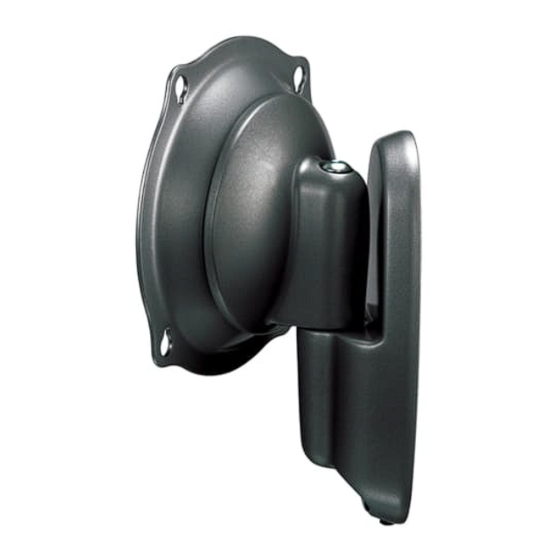
The JWP Pivot/Pitch wall mount is designed for mounting
a medium sized flat panel display. The mount can be
tilted up and down to 15° of center as well as pivot left
and right.
The JWP is shipped with the VESA
Centris™ interface which is compatible with most
medium flat panels.
To accommodate other mounting patterns in displays,
the JWP comes with a VESA Plate that accommodates
other VESA 200mm x 100mm and 200mm x 200mm
mounting patterns. This VESA Plate can also be used
with an MSB Custom Interface for non-VESA screens.
By design, the JWP can be configured to fit your medium
flat panel display, providing that your display does not
exceed the specified weight rating.
BEFORE YOU BEGIN
•
CAUTION:
To prevent damage to your display and/or the JWP, which could affect or void factory
warranty, thoroughly study all instructions and illustrations before you begin to install the mount. Pay
particular attention to ALL Warnings and Cautions in this document.
•
The maximum weight allowable for use with the JWP wall mount is 75 lbs (34 kg).
•
The JWP wall mount is designed to be installed using wall studs or supporting framework. The structure to which
the JWP wall mount is anchored must be capable of supporting five times the total weight of the mount and all
attached equipment.
•
If you have any questions about this installation, contact Chief Manufacturing at 1-800-582-6480.
®
100mm/100mm
CHIEF MANUFACTURING INC.
1-800-582-6480 952-894-6280 FAX 952-894-6918
8401 EAGLE CREEK PARKWAY, STE. 700
SAVAGE, MINNESOTA 55378 USA
I N S T R U C T I O N S
JWP-210
8832-000074 (Rev. B)
©2005 Chief Manufacturing
www.chiefmfg.com
10/05
Advertisement
Table of Contents

Subscribe to Our Youtube Channel
Related Manuals for CHIEF JWP-210


Summary of Contents for CHIEF JWP-210
-
Page 1: Before You Begin
JWP wall mount is anchored must be capable of supporting five times the total weight of the mount and all attached equipment. • If you have any questions about this installation, contact Chief Manufacturing at 1-800-582-6480. CHIEF MANUFACTURING INC. 8832-000074 (Rev. B) 1-800-582-6480 952-894-6280 FAX 952-894-6918 ©2005 Chief Manufacturing... -
Page 2: Dimensional Drawing
Installation Instructions JWP-210 IMPORTANT WARNINGS and CAUTIONS! WARNING A WARNING alerts you to the possibility of serious injury or death if you do not follow the instructions. CAUTION A CAUTION alerts you to the possibility of damage or destruction of equipment if you do not follow the corresponding instructions. -
Page 3: Table Of Contents
Installation Instructions JWP-210 CONTENTS TOOLS REQUIRED FOR INSTALLATION DIMENSIONAL DRAWING........2 TOOLS REQUIRED FOR INSTALLATION .....3 • Electric drill and bit set INSPECT UNIT BEFORE INSTALLING ....3 • Hex wrench set SPECIFICATIONS ............3 • Phillips screwdriver INTRODUCTION ............4 • Reference Chart............4 Level Mounting-Hole Configurations .......4... -
Page 4: Introduction
Installation Instructions JWP-210 INTRODUCTION There are three main steps in the JWP-210 installation process. These steps are: • Selecting an appropriate mounting configuration. • Connect display cables • Making required adjustments Before starting the installation process, determine the correct mounting-hole configuration for your display by reviewing the information located within Table 2. -
Page 5: Components
Installation Instructions JWP-210 COMPONENTS Figure 2 shows the parts and parts bags shipped with JWP. Centris Bracket (See notes) Set Screw (see Figure 2. JWP Components... -
Page 6: Parts
Installation Instructions JWP-210 PARTS Table 3 provides a list of the individual part and parts bags shipped with JWP parts. Table 3. JWP Parts List Item Description Notes JWP MOUNT See page 5 for graphic. — Interface Adapter Use with 50 —... -
Page 7: Secure Wall Bracket
Installation Instructions JWP-210 SECURE WALL BRACKET Pilot Holes WARNING: It is the responsibility of the installer to verify that the surface to which the mount is anchored will safely support the combined load of all attached components and equipment. Install wall bracket as follows: 1. -
Page 8: Recess Mount Centris Bracket To Display
Installation Instructions JWP-210 Recess Mount Centris Bracket to Display To recess mount Centris bracket: 1. Lay display down on a flat surface. CAUTION: Make sure surface is clean and free of dirt and debris before laying display down. 2. Select four screws M4 x 20mm screws (80) and four Display spacers (130) from parts bag. -
Page 9: Installation (200Mm X 200Mm)
Installation Instructions JWP-210 INSTALLATION (200mm x 200mm) 80,90, 100 or 110 WARNING: It is the responsibility of the installer to use the correct diameter and length of fastener to attach interface to back of display. Failure to do so may cause damage to the display or personal injury. -
Page 10: Installation (Msb Custom Interface)
Installation Instructions JWP-210 INSTALLATION (MSB CUSTOM INTERFACE) Attach Display to Centris Bracket NOTE: Many MSB Custom Interface brackets require the use of the VESA Plate (20) and the 10-24 Nylock nuts shipped with this mount. Follow specific instructions received with the MSB Custom Interface to install the MSB to back of display. -
Page 11: Attach Mount To Wall Bracket
Installation Instructions JWP-210 ATTACH MOUNT TO WALL BRACKET To attach mount to wall bracket: 1. Align top of mount (10) with top of wall bracket (30). Push bottom of mount against bottom of wall bracket until mount fits snugly in place (see Figure 14). -
Page 12: Cable Management
Installation Instructions JWP-210 CABLE MANAGEMENT Lateral Tension Adjustment Bolt WARNING: Make sure your cables do not run through a pinch points. Do not put your fingers between movable parts. For cable management (not shown), connect and secure power/audio/video cables, making sure to leave sufficient slack to allow for movement of the display.
Need help?
Do you have a question about the JWP-210 and is the answer not in the manual?
Questions and answers