
Subscribe to Our Youtube Channel
Related Manuals for Potterton Paramount two


Summary of Contents for Potterton Paramount two
- Page 1 Aprill 2011 Paramount two Wall hung condensing boiler 30 – 115kW Installation, operation & maintenance manual Working towards a cleaner future heating specialists...
-
Page 2: Table Of Contents
3.2 Dimensions and connections PARAMOUNT two 60-115 . . 11 3.3 Technical Data PARAMOUNT two ....13 3.4 Wiring diagram ......14 3.5 Sensor value tables. - Page 3 (Press information button) ....74 11.Commissioning report ....76 PARAMOUNT two 30 - 115 kW...
-
Page 4: Regarding This Manual
Attention! If warning is not observed, danger exists for environ- ment and the device. Note/tip: Here, you can find background information and useful tips. Reference to additional information in other documents. For whom is this manual intended? This installation manual is intended for the heating specialist. POTTERTON COMMERCIAL... -
Page 5: Safety
Commissioning must only be carried out by personnel approved and competent to do so. This facility is available from Potterton Com- mercial Service Office. Important: the boiler unit is supplied in accordance with Potterton Commercial quality assurance plan registered to meet the require- ments of BSN ISO 9002. -
Page 6: Installations/Instructions
For optimum utilisation condensing boilers should be operated at a low return temperature. However the PARAMOUNT two will also work at designed temperatures of 70/50°C. In the condensing mode as the return temperature is below the dew point (dew point is 53°C at 8.5 % CO... -
Page 7: Approvals
Voltage Directive 73/23/EEC as well as Directive 89/336/EEC (Electromagnetic Compatibility EMC) of the Council for Unification of Legal Regulations of the members Countries. The boiler fulfils the basic requirements of the Boiler Efficiency Directive 92/43/ EEC for condensing boilers. PARAMOUNT two 30 - 115 kW... -
Page 8: Conformity Declaration
Safety Conformity declaration Paramount two 30 - 115 POTTERTON COMMERCIAL... -
Page 9: Technical Data
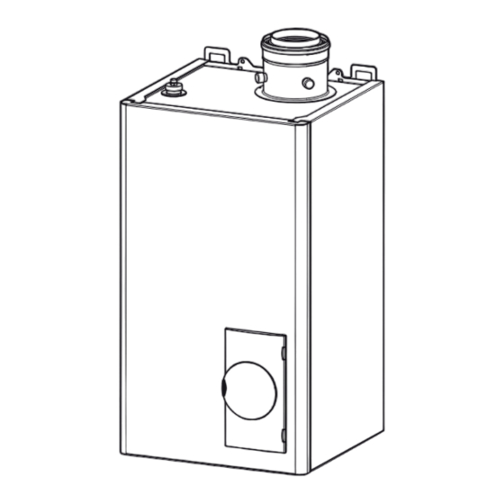
Technical Data Technical Data Dimensions and connections PARAMOUNT two 30/40 Fig. 1: Dimensions and connections PARAMOUNT two 30/40 PARAMOUNT two 30 - 115 kW... - Page 10 Technical Data Table 1: Dimensions and connections PARAMOUNT two 30/40 Model 30 / 40 – Heating flow G 1“ – Heating return G 1“ – Gas connection “ – Safety valve “ – Condensate water connection Ø 25 mm Dimension A [mm]...
-
Page 11: Dimensions And Connections Paramount Two 60-115
Technical Data Dimensions and connections PARAMOUNT two 60-115 Fig. 2: Dimensions and connections PARAMOUNT two 60-115 aGR030B PARAMOUNT two 30 - 115 kW... -
Page 12: Technical Data
Technical Data Table 2: Dimensions and connections PARAMOUNT two 60-115 Model Paramount Paramount Paramount Paramount 60 D 80 D 90 C 110 C – Heating flow “ – Heating return “ – Gas connection G 1“ – Safety valve “... -
Page 13: Technical Data Paramount Two
Technical Data Technical Data PARAMOUNT two Table 3: Technical data PARAMOUNT two Model PARAMOUNT two CE Number CE-O085BL0514 VDE-Reg.-No. 137392G applied output @ 50/30°C 31,3 59,5 79,1 98,3 118,6 output @ 80/60°C 29,1 36,8 56,2 74,6 92,2 111,7 input kW net MAX... -
Page 14: Wiring Diagram
Technical Data Wiring diagram POTTERTON COMMERCIAL... -
Page 15: Sensor Value Tables
Table 5: Resistance values for flow sensor, DHW sensor, return sensor, sensor B4 Ω Temperature [°C] Resistance [ 32555 25339 19873 15699 12488 10000 8059 6535 5330 4372 3605 2989 2490 2084 1753 1481 1256 1070 PARAMOUNT two 30 - 115 kW... -
Page 16: Before Installation
0.08 0.05 Clean combustion air! The PARAMOUNT two must only be installed in rooms with clean combustion air. Under no circumstances must e.g. pollen or the li- kes enter through the intake openings into the inside of the PARA- MOUNT two. -
Page 17: Corrosion Protection
Preferably, agents from the same manufacturer should be used. The instructions of the additive manufacturer have to be observed. Released additives Currently, the following agents have been approved by POTTERTON Commercial: – “Full heating protection“ from Fernox – “Sentinel 100“ from GE Betz As a single frost protection agent, also Tyfocor®... -
Page 18: Notes For Installation Location
Before installation Notes for installation location Attention! When first installing the PARAMOUNT two for heating operation or in connection with a DHW storage, the following has to be observed: In order to prevent damage to the boiler due to water quality, par- ticularly due to leakages in the tank, suitable precautionary measures should be taken regarding installation. -
Page 19: Application Example
Before installation Application example PARAMOUNT two 30 - 115 kW... - Page 20 Before installation POTTERTON COMMERCIAL...
-
Page 21: Installation
For this, fill 0.25 l of water into the exhaust gas flue pipe before assembly of the flue system. Filling the heating system • Fill the heating plant via the return of the PARAMOUNT two. • Check tightness (max.water test pressure 34 bar). Flue connection For the operation of PARAMOUNT two, the flue must be designed for flue temperatures below 120°C (flue type B). -
Page 22: Flue System
For lengths longer than specified in the table please contact the Technical Department for suitability. Note: Flue sizes shown for the Concentric Vertical Flue are adapted sizes for flues supplied by POTTERTON Commercial. For flues supplied by other manufactors, please refer to technical data for standard spigot sizes. -
Page 23: Flue Terminal Positioning
The flue gas pipe must be installed with a slope from the PARA- MOUNT two so that condensate from the flue gas pipe can drain into the central condensate sump in the PARAMOUNT two. The minimum slope is as follows: –... -
Page 24: Gas Connection
De-air gas pipe The gas pipe has to be de-aired before commissioning. Factory settings The PARAMOUNT two has been set at nominal heat load by the ma- nufacturer. The gas type can be seen on the glued on additional plate on the boiler. -
Page 25: Co -Content
(section 5.11 „Guide Values for Injector Pressu- re”). The CO -content at full load, as well as, low load must be between the values according to section 3.2 „Technical Data PARAMOUNT two” (page 13). PARAMOUNT two 30 - 115 kW... -
Page 26: Gas Valve
Installation 5.10 Gas valve Fig. 5: Gas valve (setting for injector pressure with key Torx T15) PARAMOUNT two 30 / 40 (Fa. Siemens VGU) Setting for full load Measuring nozzle for injector pressure Setting for lowl load (please remove protective cap) - Page 27 Measuring nozzle for connection pressure Adjusting and Checking the CO2 values Operate the PARAMOUNT two in the controller stop mode to adjust check the CO2 value. Controller Stop Mode (manual adjustment of burner load) • Press operation mode button Heating Operation for approxima- tely 3 seconds, until the message Regulator Stop Function ON is displayed.
-
Page 28: Guide Values For Injector Pressure
Guide values for gas flow, injector presure and CO -content The listed values in tab. 9 are to be used as guide values. Table 9: Guide Values for injector pressure (full load) Model PARAMOUNT two Nominal Heat Load Heating kW 6.5-30.0 9.0-38.0 14.0-58.0 20.0-77.0 20.0-90.0 25.0-110.0... - Page 29 Contact protection and international protection IPx4D To ensure contact protection and international protection IPx4d, the covering parts to be screwed, have to be fastened again with the respective screws after opening the PARAMOUNT two. PARAMOUNT two 30 - 115 kW...
-
Page 30: Commissioning
DHW should start one hour before time programe 1 and 2 start. Individual time program The boiler can be commissioned having its standard values. For adjusting parametres like individual time program, please con- sider the information given in the section Programming. POTTERTON COMMERCIAL... -
Page 31: Programming Of Necessary Parameters
– Copy the commissioning sheet with confirmation and legally binding signature to the customer. All components have been in- stalled according to the instruction of the manufacturer. The whole plant complies with the relevant British Standards and current building regulations. PARAMOUNT two 30 - 115 kW... -
Page 32: Operation
Operation Operation elements Fig. 9: Operating elements Operating mode button heating operation Operation mode button DHW operation Operating unit Display Boiler temperature ESC-button (Stop) OK-button (Acknowledgment) Chimney-sweep Information button Rotating knob Operating switch Pressure gauge Lock-out reset button POTTERTON COMMERCIAL... -
Page 33: Displays
– Automatic summer/winter switch-over (automatic switching over between heating and summer operation from a certain outside temperature on) – Automatic day heating limit (automatic switch from heating to summer operation, if outdoor temperature exceeds comfort no- minal value) PARAMOUNT two 30 - 115 kW... - Page 34 Further information about the fault can be called up by pressing the information button (see fault code table). Servicing message When the servicing symbol appears in the display, a servicing message exists or the plant is in a special mode. POTTERTON COMMERCIAL...
- Page 35 – Change to Yes and wait until value is switching back to No – Leave menu by pressing ESC You can find more information for adjusting parameters in the sec- tion section 8. „Programming”. PARAMOUNT two 30 - 115 kW...
-
Page 36: Programming
Boiler Solar Buffer storage tank DHW storage tank Direct DHW charging Configuration Fault Maintenance/Service State Diagnostics heat generation Diagnostics consumers Not all menu points are visible, depending on the selection of setting level and programming! POTTERTON COMMERCIAL... -
Page 37: Modification Of Parameters
Time and date Hours/minutes Acknowledge selection with Carry out hour setting (e.g. 15 hours) with Time and date Hours/minutes Acknowledge setting with Carry out minute setting (e.g. 30 minutes) with Time and date Hours/minutes PARAMOUNT two 30 - 115 kW... -
Page 38: Setting Table
Function Standard value fied -No. value level Time and date Hours/minutes 00:00 (h:min) Day/month 01.01 (day. month) Year 2004 (year) Operating unit Language English Contrast of display Operation lock OFF | ON Programming lock OFF | ON POTTERTON COMMERCIAL... - Page 39 Parameter only visible, if heating circuit 2 exists! heating circuit 2 Pre-selection Mo-Su Mo - Su Mo-Su | Mo-Fri | Sa-Su | Mo |Tue |Wed Thu | Fri | Sa | 1st phase ON 06:00 (h/min) 1st phase OFF 22:00 (h/min) PARAMOUNT two 30 - 115 kW...
- Page 40 Holidays heating Parameter only visible, if heating circuit 2 exists! circuit 2 Start --.-- (day. month) Finish --.-- (day. month) Operation level Reduced Frost protection | Reduced Heating circuit 1 Comfort nominal value 20.0°C Reduced nominal value 18.0°C POTTERTON COMMERCIAL...
- Page 41 Nominal value 1610 55°C Reduced nominal value 40°C 1612 Release 1620 Time programme 24h/day | Time programmes Heating circuits | 4/TWW Time programme 4/TWW Legionella function 1640 Fixed weekday Off | Periodically | Fixed weekday PARAMOUNT two 30 - 115 kW...
- Page 42 Pump hydraulic bypass | Feed pump Q8 | Basic func- tion K2 | TWW-charging | Threshold analoguous sig- nal RelCl | Exhaust gas flap | Collector pump | Fan switch-off | Pump Q1 | DHW mixing pump Q35 POTTERTON COMMERCIAL...
- Page 43 | Generator lock sensor Ext. Flow nominal value maximum 5975 100 °C Ext. Power specification threshold 5976 Function input SolCl 5978 none No | collector sensors Time constant building 6110 10 h ConfigContr1.0 6240 ConfigContr1.1 ConfigContr1.4 PARAMOUNT two 30 - 115 kW...
- Page 44 Outside temperature 8700 Outside temperature decreased 8703 Outside temperature mixed 8704 Room temperature 1 8740 Room nominal value 1 Flow temperature 1 8743 Flow nominal value 1 Room temperature 2 8770 Room nominal value 2 Flow temperature 2 8773 POTTERTON COMMERCIAL...
- Page 45 All parameters from program number 500 onwards are stored on the controller and, therefore, identical. The value modified last, is the valid value. PARAMOUNT two 30 - 115 kW...
-
Page 46: Explanations For Setting Table
HCP have to be operated together with heating circuit 1 or in- dependent from heating circuit 1 by the operator unit. Action occupancy button The effect of the presence button on the heating circuits has to be (48) set under prog. no. 48. POTTERTON COMMERCIAL... - Page 47 Heating curve slope The flow temperature nominal value is formed with the help of the (720, 1020) heating curve, which is used to control the flow temperature de- pending on the weather. PARAMOUNT two 30 - 115 kW...
- Page 48 When reaching the setpoint, the heating pump will be re-started and the temperature controlled to the reduced setpoint or the frost protection setpoint. The duration of the quick setback de- pends on the outside temperature, time constant building (prog. POTTERTON COMMERCIAL...
- Page 49 Curing heating (Ch): Part 2 of the temperature profile will be run through automatically. Functional/curing heating: The whole temperature profile will be run through automatically. Manually: Control to the Floor curing setpoint manually. PARAMOUNT two 30 - 115 kW...
- Page 50 The minimum permissble pump speed (NqmodMin) of the HC pump (885) is set via prog. no. 885. This speed is sufficient to guarantee suffi- cient water supply in the heating circuit, it is entered in percent of the maximum speed step. POTTERTON COMMERCIAL...
- Page 51 24h/day: The DHW temperature will be continuously controlled to (1620) the nominal setpoint independent from the time switching pro- grammes. Time programs HCs: The DHW temperature will be switched over between the nominal setpoint and the reduced setpoint depending PARAMOUNT two 30 - 115 kW...
- Page 52 Legionella function set- Setpoint, at which potentially existing legionella germs will be point killed. (1645) Legionella function With this function, the time will be set, during which the legionella duration function setpoint is activated to kill germs. (1646) POTTERTON COMMERCIAL...
- Page 53 Alarm output: The output will be set, when there is a fault in the device, which requires manual unlocking. Status information: The output is set, when the burner operates. PARAMOUNT two 30 - 115 kW...
- Page 54 Function input H1 None: No function. (5950) Modem: The modem function serves to centrally switch off the he- ating system into stand-by or reduced operation (telephone remo- POTTERTON COMMERCIAL...
- Page 55 Modem inverse: See prog. no. 5950. Warm air curtain function: See prog no. 5920. Specified setpoints (heat request:) The existing voltage signal or current signal will be converted into a temperature value and used PARAMOUNT two 30 - 115 kW...
- Page 56 Fig. 17: Specified capacity (examples) relative power Pump pressureless header: This function enables a control of the boiler at flow temperature after the hydraulic bypass. For this, a POTTERTON COMMERCIAL...
- Page 57 In addition, the diagnosis code is issued via the display (see chapter Maintenance, fault code table). Burner ctrl phase lock- Phase, in which the fault occured, which led to the disturbance. out pos PARAMOUNT two 30 - 115 kW...
-
Page 58: Manual Control
Time switching program, holiday program, operating mode, occu- Setback reduced pancy button, H1 Setback frost protection Holiday program, operating mode, H1 Room temp limitation The following messages are possible under DHW: Display Dependend on Not available Manual control active Manual control active POTTERTON COMMERCIAL... - Page 59 Not available Manual control active Manual control active Fault Frost prot collector active Collector too cold Recooling active Recooling via collector active Max st tank temp reached Storage tank charged to the security temperature PARAMOUNT two 30 - 115 kW...
- Page 60 Frost prot room active Holiday program, operating mode, H1 Summer operation 24-hour Eco active Time switching program, holiday program, operating mode, occup- Setback reduced ancy button, H1 Setback frost protection Holiday program, operating mode, H1 Room temp limitation POTTERTON COMMERCIAL...
-
Page 61: General
The value switched over to stays active until the next modification by the time program. PARAMOUNT two 30 - 115 kW... -
Page 62: Servicing
10.1 Maintenance work Maintenance work includes among others: – PARAMOUNT two Clean SOB outside. – Check connection and seal locations of water filled parts. – Check safety valves for correct function. -
Page 63: Removing Gas Burner
10.4 Removing gas burner The gas burner has to be dismantled before cleaning the heating surfaces. Dismantling of the gas burner (PARAMOUNT two 30/40) • Disconnect the connecting wires to the fan. • Disconnect ionisation cable. • Disconnect ignition cable. - Page 64 • Pull out the burner together with mixing chamber, fan and ea- haust gas muffler to the front (see figure 19)siehe Abb. 20 • Clean burner pipe with soft brush. Fig. 20: Dismantle of the gas burner (PARAMOUNT two 60 D) Remove bracket. Pull out burner with mixing chamber and flue silencer.
- Page 65 • Pull out the burner together with mixing chamber, fan and ea- haust gas muffler to the front (see figure 19)siehe Abb. 21 • Clean burner pipe with soft brush. Fig. 21: Dismantle of the gas burner (PARAMOUNT two 80 D) Disconnect flue silencer from bracket (under the housing lid).
-
Page 66: Protection Against Electrical Shock
• Pull out the burner together with mixing chamber, fan and ea- haust gas muffler to the front (siehe Abb. 22). • Clean burner pipe with soft brush. Fig. 22: Dismantle gas brenner (PARAMOUNT two 95/115) Pull out burner with Remove bracket. -
Page 67: Boiler View Paramount Two
Servicing 10.6 Boiler view PARAMOUNT two Fig. 23: Boiler views PARAMOUNT two 30/40 (depicted without front case and control cover) Flow sensor Ionisation electrode Sight glass Ignition electrode Flue adapter inspection openings Air-vent Mixing chamber Flue pipe Air silencer Gas injector... - Page 68 Servicing Fig. 24: Boiler views (depicted without front case and control cover) PARAMOUNT two 60 Flue adapter with inspection openings Air-vent Ignition transformer (under the lid) Air silencer Mixing chamber Ignition and ionisation electrode Gas injector Sight glass Gas valve...
- Page 69 95/115 Ignition transformer (under the lid) Air-vent Air silencer Ignition and ioni- Mixing chamber sation electrode Gas injector Sight glass Gas valve cleaning cover Pump replacement pipe Pressure controller Siphon Control LMU PARAMOUNT two 30 - 115 kW...
-
Page 70: Dismantling The Heat Exchanger
– At minimum power > 5 µA DC (switching threshold at 0.7 µA DC) – At maximum power 10 µA DC For measurements put the ionisation lead at spade connection at ignition assembly and attach µA DC meter between them. Caution! Do not touch plug contacts during the ignition process! POTTERTON COMMERCIAL... -
Page 71: Control And Regulating Centre Lmu
In case of fault switch-off, the reset button on the control panel should be pressed. In case of operation failure (bell symbol in the display), the digit in the display on the operating panel indicates the cause of the fault (see fault code table). PARAMOUNT two 30 - 115 kW... - Page 72 (live and neutral reversed). If the failure symbol appears, a fault exists in the plant. Further information about the fault can be called-up by pressing the infor- mation button. POTTERTON COMMERCIAL...
-
Page 73: Fault Code Table
1) 3) the safety time) period, check ignition electrode and ionisation current Flame failure during operation Reset Speed threshold of fan exceeded or undercut, fan Incorrect air supply defective PARAMOUNT two 30 - 115 kW... -
Page 74: Operation Phases Of Control And Regulation Centre Lmu (Press Information Button)
Flame monitoring with ignition Safety time variable Flame monitoring without ignition Heating mode Room heating mode, burner in operation Hot water mode HW-tank charging, burner in operation Parallel operation for heating and hot Heating and hot water mode water POTTERTON COMMERCIAL... - Page 75 Fan continues to run rating fan speed Subsequent ventilation with pre-pur- Fan continues to run ging fan speed Shutdown Self-test after controlled shut-down Fault position The actual fault code is displayed, see fault code table PARAMOUNT two 30 - 115 kW...
-
Page 76: Commissioning Report
NOTE: It is the installer’s responsibility to ensure that the boiler is correctly commissioned by a competent engineer and that this report is completed and kept as a record. A commissioning service available from Potterton at the address listed on the back page of this manual. When a Potterton engineer commissions, this completed report will be sent to the installer. - Page 77 Is oil filter fitted? YES / NO SIGNATURE 7.23¶ Is fire valve fitted? YES / NO Oil supply: Single Pipe DATE 7.24¶ Two Pipe Ring Main Document ID Ref: PCF/029/5 COMMENTS ON ACCESSIBILITY FOR MAINTENANCE PARAMOUNT two 30 - 115 kW...
- Page 78 - Menu points 36 Explanations for setting table 46 - Setting levels 36 Protection against contact 29 Protection operation 34 Fault 73 Fault message 33 - Table 73 Quick setback 48 Floor curing function 49 flow and return connections 21 POTTERTON COMMERCIAL...
- Page 79 Setting nominal room value 34 Setting table 38 Stop drinlking water operation 34 Stop heating operation 33 Strain relief 28 Supply Pressure 24 Symbols in the display 33 Time and date 46 Time programmes 47 Used symbols 4 PARAMOUNT two 30 - 115 kW...
- Page 80 Authorised User No. 00174 Authorised User No. Baxi Commercial Division Sales: Technical: Wood Lane, Erdington, 0845 070 1056 0845 070 1057 Birmingham B24 9QP Email: potterton.commercial@baxicommercialdivision.com heating specialists www.pottertoncommercial.co.uk...
Need help?
Do you have a question about the Paramount two and is the answer not in the manual?
Questions and answers