Table of Contents
Advertisement
Advertisement
Table of Contents

Related Manuals for PIKO Digi 1


Summary of Contents for PIKO Digi 1
- Page 1 PIKO digital Manual...
-
Page 2: Getting Off To A Quick Start
Getting off to a quick start : 1. Connect the adapter and the Digi 1 as described on page 8 under "Connection and Operation". 2. The locomotives in the start set have been allocated addresses, which are shown on the labels on the bottom of the locos together with the transmission channel for the PIKO Digi remote control. -
Page 3: Analogue Versus Digital A Fundamental Decision
First of all we should like to congratulate you on acquiringyour new PIKO Digital Start Set. You have taken a decisive step into the fascinating world of PIKO model railways. Since you have decided on a digital system, unquestionably the modern way for run-... -
Page 4: Analogue And Digital Technology - The Fundamentals
With analogue technology the speed of PIKO locos is controlled by the voltage (0 - 14V). This is achieved by a controller such as the PIKO Speed control #55003 (speed con- trol with mains adapter) or the transformer with speed regulator #55002. -
Page 5: Piko Digi 1 - Introduction
This system which is based on the PIKO Digi 1 makes it easy for any PIKO model rail enthusiast to set up a digital layout in easy stages. - Page 6 PIKO Digi 1 extended with PIKO Digi 2 and two isolated rail circuits: isolating track connection PIKO Digi 1 extended with two Digi 2 and three isolated rail circuits (maximal level of construction; 10 PIKO Digi 2): isolating track connection...
-
Page 7: Piko Digi 1 - The Functions
10 metres. With the PIKO Digi remote control and the PIKO Digi 1 a maximum of 127 locos can be addressed on a digital layout and their direction of travel and speed as well as their other special functions controlled. -
Page 8: Connection And Operation
MUST be removed. If the condenser is left in the Connecting Clip it will elimina- te the high frequency control impulses and neither locos or accessories will work. Next the 4 batteries for the PIKO Digi remote control must be inserted into the battery compartment on the back as described. - Page 9 Now fit the adhesive pad to the base of the PIKO Digi 1. This will fix it to the model rail layout so that the PIKO Digi remote control can always be aimed at the PIKO Digi 1. There must be no obstacle between the PIKO Digi remote control and the PIKO Digi 1 that could block the Digi remote’s infra red signals to the Digi 1.
-
Page 10: Using The Piko Digi-Fern Remote Control
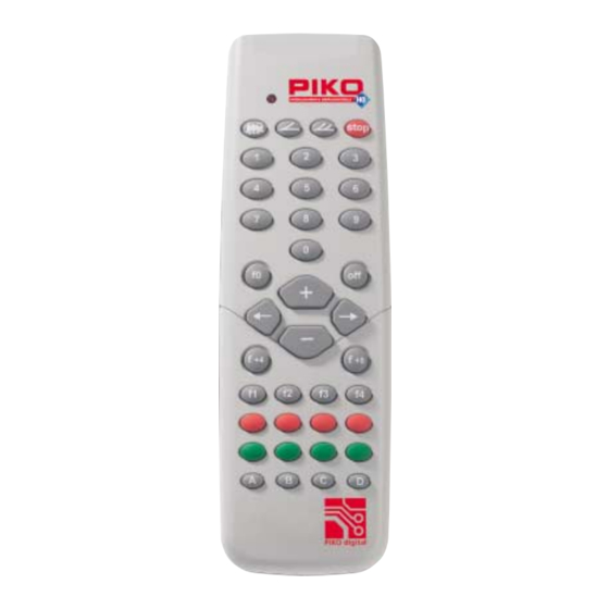
Using the PIKO Digi-fern remote control control LED shows the current activity in the PIKO Digi-fern remote control stop key to switch the track current on and off loco key to initiate selection of the loco address electromagnetic accessory key to... -
Page 11: Control Led
1. Control LED As long as a key is being pressed on the PIKO Digi remote control, the remote control sends an infra red signal. This activity is shown by the control LED. 2. Transmission channel The PIKO Digi 1 uses 4 transmission channels for the controls. The transmission signal can... -
Page 12: Speed Control
0 and 127. This means you can enter 8 digits if you like but the PIKO Digi remote control only retains the last three. If an invalid address is entered control remains with the previously selected locomotive. -
Page 13: Selecting The Direction Of Travel
1 and 256. This means you can enter 8 digits if you like but the PIKO Digi remote control only retains the last three. If an invalid address is entered con- trol remains with the previously selected magnetic component. -
Page 14: Programming Loco Decoders
(up to 3) digits entered provided these are within the range 0 to 127. This means that you can enter 8 digits but the PIKO Digi remote control only retains the last 3 digits. If an invalid address is entered the programming process is not initiated. -
Page 15: Power On / Off
The programming process is not started because the last 3 digits are 623 and this is not a valid address between 0 and 127. Every loco which is programmed with the PIKO Digi 1 receives the loco address entered on the PIKO Digi remote control and is switched into the 28 speed mode. -
Page 16: Led Signals
• Max. power pickup: 28VA (N.B.: mains adapters or transformers of more than 45 VA capacity must not be connec- ted to the PIKO Digi 1 or PIKO Digi 2. Doing so can lead to damage to the electronic components.) •... -
Page 17: Controlling More Than 2 Locomotives
PIKO Digi 1. N.B.: Never connect 2 mains adapters in parallel to the same PIKO Digi 1 or to the same connection clip. This would destroy the PIKO Digi 1. Moreover, this parallel connection... - Page 18 To ensure that the strength of the signal sent by the PIKO Digi 1 is adequate no more than 10 PIKO Digi 2 units should be connected to one PIKO Digi 1. You should make sure that the length of the lead from each PIKO Digi 2 to the PIKO Digi 1 does not exceed 2 m.
-
Page 19: The Power Peak The Piko Digi Power Box
- The PIKO Digi 1 is then switched on again using the stop key on the PIKO Digi remote control. And now everything proceeds normally again. If the LED on the PIKO Digi 1 is not on and is not flashing, the mains adapter has swit- ched off: - the cause of the short circuit must now be eliminated or the power requirement of the locomotives reduced (e.g. -
Page 20: The Piko Digital Basic Set, # 55011
The PIKO digital basic set, # 55011 If you have a conventional PIKO layout and would like to convert it to a digital layout, you can achieve this with the PIKO basic set. This contains all the elements required to convert your PIKO model rail layout to a digi- tal system: •... -
Page 21: Any Other Queries
N.B.: It may be possible for you to use your existing transformer as the power supply for your PIKO Digi 1 or PIKO Digi 2. For this it must deliver a constant voltage of 14 V to 16 V AC or DC. The voltage must not fall below 14 V or exceed 16 V. -
Page 22: Supplementary Digital Components From Piko
55007 Desk top transformer T4 72VA 55005 Desk top transformer T3 28VA Can be used to supply power to the PIKO Digi power box or Can be used to supply power to PIKO Digi 1 as a lighting transformer... -
Page 23: Table Of Contents
Using the PIKO Digi-fern remote control ........ - Page 24 PIKO Spielwaren GmbH · Lutherstr. 30 · 96505 Sonneberg Tel. 03675 897242 · e-mail: hotline@piko.de · www.piko.de © 2005 PIKO Spielwaren GmbH...
Need help?
Do you have a question about the Digi 1 and is the answer not in the manual?
Questions and answers