PIKO 35028 - R/C Analog Power Set Quick Start Manual
- Quick start manual (2 pages)
Advertisement
Contents
- Pocket remote (Transmitter)
- 22 V DC 5 A Safety-Approved 120 V Power Supply
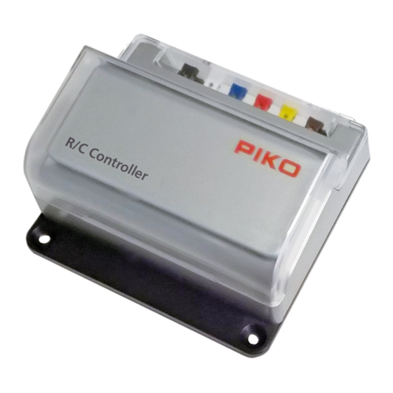
- R/C Analog DC Controller (Receiver)
- DC adapter cable for power supply
Technical data
Transmitter (Pocket Remote)
Number of channels: 8
Frequency range: 2.4 GHz
Range approx.: 30 m
Power supply: 1x 3 V CR2025
Weight approx.: 30 g
Receiver (R/C Analog DC Controller)
Number of channels: 8
Speed steps: 28 (14 steps if supplied with 7-16 V input)
Frequency range: 2.4 GHz
Range approx.: 30 m
Power supply: 16-24 V DC
Max. current: 4.5 A Max to Track
2 A Max for Accessories; 5 A Max Combined
Weight approx.: 150 g
Power Supply
Input: 100 – 240 V AC
Output: 22 V DC 5 A
Weight approx. 300 g
FOR INDOOR USE ONLY
Installation and Connection

Connect the track power clamps and any DC accessories (switch control boxes, lights, etc.) to the correct terminals on the back of the R/C Controller (1). Connect the "pigtail" power cord adapter to the input terminals on the back of the R/C Controller. Note the correct polarity of the wires (2). Connect the pigtail to the plug on the power supply (3). Make sure to have an operating Pocket Remote set to the same channel as the R/C Controller and in-hand to immediately control operation. Then, after confirming that all connections are correct and secure, plug the power supply into a 120V grounded AC outlet (4).
Channel Selection
To communicate with each other, the R/C Controller (Receiver) and Pocket Remote (Transmitter) must both be set to the same channel. They are factory set to channel 0, but any one of the 8 channels, numbered 0-7, may be selected.
Up to 8 sets of R/C Controllers and Pocket Remotes can operate in the same area without interference by setting each set to a different channel. Or, one Pocket Remote can operate up to 8 R/C Controllers by setting them all to the same channel.
If using a 35040 Loco Receiver in the same area, keep in mind that this operates in the same channel range. And it may be necessary to use a different channel to avoid interference with other nearby radio devices in the 2.4GHz radio range.
R/C Controller (Receiver):

- Lift up the clear plastic lid on the R/C Controller.
- Pull off the cover.
- Now you have access to the DIP rotary switch.
- The direction of the arrow indicates the channel that has been set.
- Use a small flat screwdriver to set the channel on the DIP turn switch.
Pocket Remote (Transmitter):

- Remove the small cover on the back of the Pocket Remote.
- You now have access to the DIP rotary switch.
- The arrow direction indicates the set channel.
- You can adjust the channel by turning it with a small flat screwdriver.
Operation with the R/C Speed Controller
The operation is simple. By pressing the buttons on the Pocket Remote, you can select the direction of motion, speed step, switch the accessory output and trigger an emergency stop.

1x  = Forward driving direction, speed step 1
2x = Forward driving direction, speed step 2, and so on, up to 28
If you are already driving forwards with the locomotive, you can use the button to increase the speed (speed steps). By pressing ![]() , you can decrease the speed.
, you can decrease the speed.
You can press the buttons briefl y, which only changes one speed step at a time, or you can keep the buttons pressed, which causes the speed to change continuously.
Using the included transformer in the 35028 set, the R/C Controller adjusts the track voltage in 28 steps from zero to full-voltage, in both directions.
1x ![]() = Reverse driving direction, speed step 1
= Reverse driving direction, speed step 1
2x ![]() = Reverse driving direction, speed step 2, and so on, up to 28
= Reverse driving direction, speed step 2, and so on, up to 28
If you are already reversing with the locomotive, you can use the button ![]() to increase the speed (speed steps). Press the button to reduce the speed.
to increase the speed (speed steps). Press the button to reduce the speed.
 = Accessories on/off
This toggles on/off the fi xed DC accessory outputs on the R/C Controller.
 = Emergency stop
Notes on Operation:
The starting response of each locomotive is different. Locos with decoders or other electronics generally require a higher voltage on the track before starting to move. In some cases, the arrow key may need to be pressed several times (or held down) before the train starts to move.
Also, the terms "forward" and "reverse" are used here only for reference. As with any analog DC throttle, depending on which direction the train is facing on the tracks, pressing "forwards" may cause the train to move either forward or reverse.
PIKO Spielwaren GmbH · Lutherstraße 30 · 96515 Sonneberg, GERMANY

Documents / ResourcesDownload manual
Here you can download full pdf version of manual, it may contain additional safety instructions, warranty information, FCC rules, etc.
Download PIKO 35028 - R/C Analog Power Set Quick Start Manual
Advertisement


Need help?
Do you have a question about the 35028 and is the answer not in the manual?
Questions and answers