Table of Contents
Advertisement
Advertisement
Table of Contents

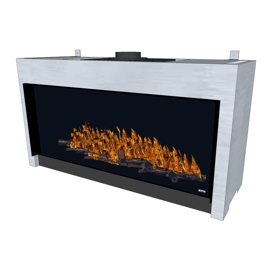
Summary of Contents for Faber Relaxed Premium L
- Page 1 Relaxed Premium L Installation guide...
- Page 2 1 < < < <...
- Page 3 2 < < < <...
- Page 4 3 < < < <...
-
Page 5: Table Of Contents
Index Introduction ..................5 Safety instructions.................. 6 Installation requirements ................. 6 The fire ..................7 False Chimney breast ................ 7 Requirements flue system and outlets............ 7 terminals ..................7 Existing chimney ................8 Preparation and Installation instructions ............9 Gas connection ................9 Electric connection ................ -
Page 6: Introduction
12.1 Please note : only a vertical flue installation, ......... 17 Technical data .................. 18 Dimension of the appliance ..............19 Dimension Ventilation Grills..............20 Dimension Service Hatch..............21 1 Introduction 5 < < < <... -
Page 7: Safety Instructions
The appliance can only be installed by a competent person in accordance with the Gas Safety. We urgently advise you to read this installation manual properly. This appliance complies with the guidelines for European gas appliances (Gas Appliances Directive) and bears the CE mark. 2 Safety instructions. -
Page 8: The Fire
The false chimney breast and its construction may not rest on the appliance Requirements flue system and outlets You should always make use of the materials prescribed by Faber International Ltd. Only by using these materials can Faber International Ltd. guarantee a proper functioning. -
Page 9: Existing Chimney
systems . For a proper functioning the terminal should be at least 0.5 m. away from: Corners of the building. Roof overhangs and balconies. Eaves (with the exception of the roof ridge). Existing chimney You can also connect the appliance to an existing chimney. The existing chimney will function as an air supply and a flexible stainless steel pipe drawn up through the chimney will remove the combustion gas. -
Page 10: Preparation And Installation Instructions
4 Preparation and Installation instructions Gas connection The gas connection must comply with locally valid standards. We advise Pipe work from the meter to the appliance must be of adequate size., with near the appliance a gas isolater tap that should always be accessible. Place the gas connection in such a way that this is easily accessible, and that before service, the burner unit can be disconnected at all times. -
Page 11: Mounting The Smoke Emission Outlet Materials
Mounting the smoke emission outlet materials In case of a wall or roof terminal, the hole must be at least 5 mm bigger than the diameter of the flue material. Horizontal parts must be installed at a (3 degree) slope up away the appliance. ... -
Page 12: Removing The Glass
5 Removing the glass Remove the cover strips on the side. (see fig. 2.1 Remove cover strip on the bottom. (see fig. 2.2 ) Place the suction discs onto the glass. Remove the sealing cord from the groove (see fig. 2.3) ... -
Page 13: Checking The Installation
7 Checking the installation. Checking the ignition of the pilot burner, main burner. Start the pilot and main burner according to the instructions in the user’s manual. Check whether the pilot light is properly positioned above the main burner and is not covered by chips, an imitation log or pebbles. -
Page 14: Checking The Flame Picture
Checking the flame picture. Allow the applaince to burn for at least 20 minutes at full and then check the flame picture for: 1. Distribution of the flames 2. Colour of the flames If either one or both points are unacceptable, then check: ... -
Page 15: Annual Maintenance
9 Annual maintenance Service and cleaning: Check and clean if necessary after checking: o The pilot light o The burner (in an LPG flat burner replace the burner sheet) o The combustion chamber o The glass o The logs for possible fractures o The outlet Replace: o (in an LPG flat burner replace the burner sheet) -
Page 16: Calculation Of Flue System
11 Calculation of flue system The possibilities for the lengths of flue pipes and the possible restrictors have been recorded in a table (see chapter 12 ) This table works with a vertical and a horizontal length. To define the vertical length all lengths of flue pipes in a vertical direction should be added up. -
Page 17: Sample Computations
11.2 Sample computations Sample calculation 1 Count the horizontal lengths Flue pipe lengths C+E = 1 + 1 Bend D = 1 x 2 m Total Count the vertical lengths Flue pipe length A Roof terminal G Total Sample calculation 2 Count the horizontal lengths Flue pipe lengths J + L = 0,5 + 0,5 1 m Bends... -
Page 18: Table
12 Table Find the correct vertical and horizontal lengths in the table. In case of an “x”, or if the values are outside the table, the combination is not permitted. The value found indicates the width of the restrictor to be placed ("0" means no restrictor should be placed). -
Page 19: Technical Data
13 Technical data II 2H3+ II 2H3+ II 2H3+ Gas category C11/ C31 C11/ C31 C11/ C31 Type of appliance Reference gas 10.5 10.5 10.5 Input Nett Efficiency class NOx class inlet-pressure mbar 1090 Gas rate at 15ºC and 1013 mbar Gas rate at 15ºC and 1013 mbar gr/h 25.1... -
Page 20: Dimension Of The Appliance
14 Dimension of the appliance 19 < < < <... -
Page 21: Dimension Ventilation Grills
15 Dimension Ventilation Grills 20 < < < <... -
Page 22: Dimension Service Hatch
16 Dimension Service Hatch 21 < < < <... - Page 23 22 < < < <...
- Page 24 Saturnus 8 NL - 8448 CC Heerenveen Postbus 219 NL - 8440 AE Heerenveen T. +31(0)513 656500 F. +31(0)513 656501...


Need help?
Do you have a question about the Relaxed Premium L and is the answer not in the manual?
Questions and answers