Table of Contents
Advertisement
Advertisement
Table of Contents

Related Manuals for Fisher PRO-CASTER


Summary of Contents for Fisher PRO-CASTER
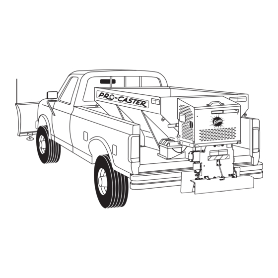
- Page 1 June 1, 2002 Regular and High Capacity PRO-CASTER™ Hopper Spreader Installation Instructions CAUTION Read this manual and engine owner,s manual before installing or operating the spreader. ® This manual is for FISHER PRO-CASTER™ Hopper Spreaders with serial numbers 0126 and higher.
-
Page 2: Table Of Contents
TABLE OF CONTENTS SAFETY INFORMATION ............................1 Before You Begin .............................. 1 Torque Chart ..............................2 Gasoline Warning Label ............................ 3 Warning/Caution Label ............................3 LOADING ................................4 Certification ............................... 4 Material Weights ............................... 4 Regular Capacity Load Weight .......................... 4 High Capacity Load Weight .......................... -
Page 3: Safety Information
SAFETY INFORMATION WARNING WARNING Hydraulic oil under pressure could cause skin Indicates a potentially hazardous situation that, injection injury. If you are injured by hydraulic if not avoided, could result in death or serious oil, get medical attention immediately. personal injury. CAUTION CAUTION If rear directional, CHMSL light or brake... -
Page 4: Torque Chart
SAFETY INFORMATION When tightening fasteners, refer to Torque Chart for CAUTION the recommended fastener values. Batteries normally produce explosive gases that can cause personal injury. Therefore, do Torque Chart not allow flames, sparks, or lit tobacco to come near battery. When charging or working near a battery, always cover your face and protect FASTENER TORQUE (FT-LB) -
Page 5: Gasoline Warning Label
SAFETY INFORMATION Please become familiar with the Warning Gasoline Warning Label and Caution labels on the spreader! WARNING Gasoline is flammable. • Turn off engine and allow it to cool before filling gas tank. • DO NOT smoke or use open flame within 25 feet of spreader. •... -
Page 6: Loading
LOADING This Manual covers vehicles which have been Certification recommended for carrying the hopper spreader. Please see your local dealer for proper vehicle NOTE: All new untitled vehicle installations applications. require National Highway Traffic Safety Administration (NHTSA) Altered Vehicle Certification Labeling. Installer to verify struck WARNING load of snow or ice control material does not Overloading could result in an accident or... -
Page 7: Spreader Mounting Instructions
SPREADER MOUNTING INSTRUCTIONS Mounting the Spreader onto the Vehicle High Capacity: Lift spreader by hooking all four loops located at the corners of the hopper. NOTE: Periodically through the snow season, verify the mounting devices are secure. Loops 1. Remove the tailgate from the truck. 2. - Page 8 SPREADER MOUNTING INSTRUCTIONS Mounting the Spreader onto the Vehicle (Continued) 3. Before lowering the spreader, place lengths of Spacer lumber (2" x 4" x 48" minimum) under the side ribs. By elevating the spreader off of the vehicle, it is easier to remove excess material that accumulates under the spreader.
-
Page 9: Chute Attachment Instructions
CHUTE ATTACHMENT INSTRUCTIONS Chute Assembly 4. Align the spinner shaft with the gearbox output 1. Remove the conveyor guard from the engine shaft. Once the shafts are aligned, move the base. spinner coupling over both shafts and insert the bolt and tighten the locknut. 2. -
Page 10: Wiring Instructions
WIRING INSTRUCTIONS Wiring Instructions Vehicle Harness Installation To properly wire the hopper spreader, please adhere to All spreaders are shipped from the factory with the the following recommended installation sequence. spreader harness wired to the engine, clutch, and electric throttle. 1. -
Page 11: Harness Plug And Hook Instructions
HARNESS PLUG AND HOOK INSTRUCTIONS 1. Install the plug cover as shown. 6. After connecting the spreader harness plug with the vehicle harness plug, secure the plug cover into the legs of the hook. Plug Cover Hook Legs Spreader Harness Plug Step 3 Vehicle Harness Plug... -
Page 12: Choke Adjustment Procedure
CHOKE ADJUSTMENT PROCEDURE Tecumseh Choke Adjustment Procedure Choke Butterfly 1. The choke linkage and choke adjustment screw is Choke Adjustment shipped from the factory with the choke butterfly Screw set to 75% fully closed choke. Retainer Screw 2. With the choke set at 100% the engine will not stay 100% running in the choked position. -
Page 13: Hydraulic Unit Installation Instructions
HYDRAULIC UNIT INSTALLATION INSTRUCTIONS Hydraulic Unit Installation Cab Control Valve Installation Recommended sequence of installation is as follows: 1. With the seat fully forward, select a suitable location to mount the cab control valve allowing for 1. Pump (not provided). the operator to adjust the control and to turn it ON and OFF. -
Page 14: Dual Hydraulic Circuit Diagram
DUAL HYDRAULIC CIRCUIT DIAGRAM Typical Hydraulic Circuit Dedicated Fixed Displacement Pump PUMP 23 GPM Min VALVE 1500 PSI Rated to 40 GPM 1500 PSI Inlet Flow from Tank Controlled Flow to Conveyor Motor: Excess Flow 10 GPM (max.) @ 1500 PSI to Tank Return Flow to Tank... -
Page 15: Final Adjustments
FINAL ADJUSTMENTS Drive Belt and Conveyor Chain Final Checklist Verify correct engine oil level. (See engine Check engine to electric clutch belt tension. Correct tension allows 1/4" - 5/16" deflection midway between manufacturers Owner’s Manual.) the pulleys. Verify the gear case oil level is level with the To increase belt tension: Loosen the four (4) bolts that fill hole. - Page 16 Fisher Engineering outlets is granted. Fisher Engineering reserves the right under its product improvement policy to change construction or design details and furnish equipment when so altered without reference to illustrations or specifications used herein. Fisher Engineering and the vehicle manufacturer may require and/or recommend optional equipment for hopper spreaders.
Need help?
Do you have a question about the PRO-CASTER and is the answer not in the manual?
Questions and answers