Table of Contents
Advertisement
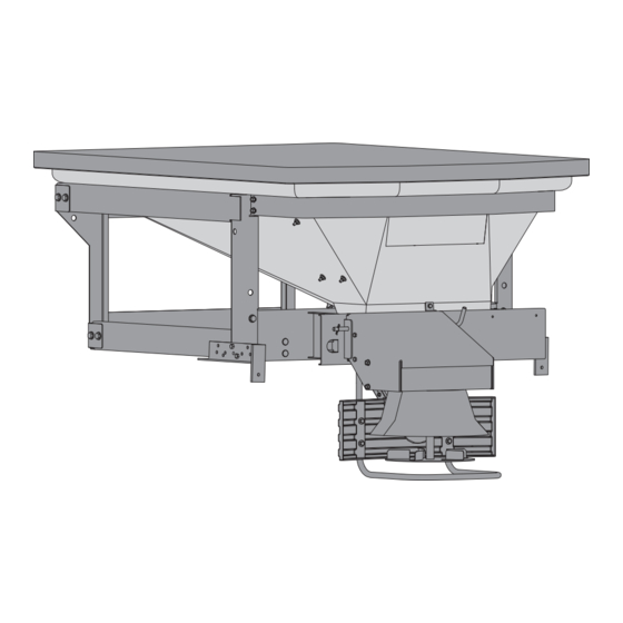
POLY-CASTER™ LT Hopper Spreader
These Installation Instructions are for FISHER
Fisher Engineering
50 Gordon Drive, Rockland, Maine 04841-2139 • www.fi sherplows.com
Installation Instructions
Read this manual before installing or
operating the spreader.
serial numbers 0000 and higher.
A DIVISION OF FISHER, LLC
CAUTION
POLY-CASTER LT hopper spreaders with
®
78902
August 15, 2013
Lit. No. 43583, Rev. 01
Advertisement
Table of Contents

Related Manuals for Fisher POLY-CASTER


Summary of Contents for Fisher POLY-CASTER
- Page 1 Lit. No. 43583, Rev. 01 POLY-CASTER™ LT Hopper Spreader Installation Instructions CAUTION Read this manual before installing or operating the spreader. These Installation Instructions are for FISHER POLY-CASTER LT hopper spreaders with ® serial numbers 0000 and higher. A DIVISION OF FISHER, LLC...
-
Page 3: Safety Information
SAFETY INFORMATION SAFETY DEFINITIONS WARNING/CAUTION LABELS Please become familiar with the Warning and Caution WARNING labels on the spreader. Indicates a potentially hazardous situation that, if not avoided, could result in death or NOTE: If labels are missing or cannot be read, see serious personal injury. -
Page 4: Serial Number Label
SAFETY INFORMATION DANGER • DO NOT REMOVE SPREADER WITH MATERIAL IN HOPPER • FASTEN SPREADER DOWN WITH APPROVED RATCHET STRAPS AND BOLT KIT • REAR FRAME LOCATOR BARS MUST BE IN PLACE BEFORE OPERATING VEHICLE D6547 ROTATING AUGER CAN CAUSE SERIOUS INJURY OR DEATH •... -
Page 5: Safety Precautions
SAFETY INFORMATION SAFETY PRECAUTIONS CAUTION • Do not operate a spreader in need of Improper installation and operation could cause maintenance. personal injury and/or equipment and property damage. • Before operating the spreader, reassemble Read and understand labels and the Owner's Manual any parts or hardware removed for cleaning before installing, operating or making adjustments. -
Page 6: Cell Phones
SAFETY INFORMATION CELL PHONES BATTERY SAFETY A driver's fi rst responsibility is the safe operation of CAUTION the vehicle. The most important thing you can do Batteries normally produce explosive gases to prevent a crash is to avoid distractions and pay which can cause personal injury. -
Page 7: Material Weights
LOADING CERTIFICATION These instructions cover vehicles which have been recommended for carrying the hopper spreader. Please see your local dealer for proper vehicle WARNING applications. New untitled vehicle installation of a spreader requires National Highway Traffi c Safety WARNING Administration altered vehicle certifi cation Overloading could result in an accident or labeling. -
Page 8: Determining Vehicle Payload
LOADING DETERMINING VEHICLE PAYLOAD Compare the maximum volume to determine the maximum height of the material in the hopper spreader. WARNING 8. Fill the hopper with the material to the calculated Overloading could result in an accident or damage. Do not exceed GVWR or GAWR height. -
Page 9: Mounting The Spreader
MOUNTING THE SPREADER MOUNTING SPREADER 4. Mount the chute/defl ector assembly to the spinner assembly with supplied hardware to form the drive assembly. NOTE: Periodically throughout the snow and ice control season, verify mounting devices are secure. 5. Mount the drive assembly to the spreader with a bent pin and secure with a hair pin cotter. - Page 10 MOUNTING THE SPREADER 8. Once the spreader is positioned front to back, 10. Install and tighten all four cap screws. center it left to right. Looking at the inside front and rear corner of the lower frame area, you will 11.
-
Page 11: Wiring Instructions
WIRING AND HARNESS INSTRUCTIONS WIRING INSTRUCTIONS 5. Connect power leads to the battery: Red POSITIVE (+), Black NEGATIVE (–). Always connect to the primary battery if using a dual 1. Take the harness assembly and route from the battery system. Secure loose loom to any other rear of the vehicle to the front. - Page 12 WIRING AND HARNESS INSTRUCTIONS 3. Push the ON/OFF switch on the control to check NOTE: In the off season, remove control and for power. After power has been confi rmed, put in a cool, dry place. The interior summer push the ON/OFF switch again to turn OFF. The temperatures could damage circuit board and electrical portion of the installation is complete.
-
Page 13: Harness Wiring Diagram
HARNESS WIRING DIAGRAM Spreader Control Control Power Cable 1/4" x 1/2" Cap Screw Control Mounting Bracket Vehicle Harness Spreader Harness Power Cable Connector Dust Cover Adapter Lit. No. 43573/43583/43593, Rev. 01 August 15, 2013... -
Page 14: Harness Diagram
HARNESS DIAGRAM Vehicle Harness Mold Cap End View White 10 GA Red 10 GA Spinner + Auger + Green 10 GA Black 10 GA Auger – Spinner – Black Orange 10 GA Blue 12 GA Vibrator – Spinner + 10 GA White Vibrator –... - Page 15 HARNESS DIAGRAM Spreader Harness Vibrator Plug 5” 19 1/2” Black Male Auger Motor Female 65 1/4” Spinner Vibrator Positive Vibrator Negative Auger Negative Auger Positive Negative Positive Spinner Positive Spinner Negative Load Load View View Control Vibrator Red Positive (+) Vibrator Black Negative (-) Auger...
-
Page 16: Electrical Routing
ELECTRICAL ROUTING Spinner Main Input Auger and Vibrator (not supplied on drawing) Lit. No. 43573/43583/43593, Rev. 01 August 15, 2013... -
Page 17: Final Adjustments
FINAL ADJUSTMENTS FINAL CHECKLIST Verify dielectric grease is applied to all electrical connections. Verify wire harnesses and battery cables are properly secured away from hot or moving parts. Verify vehicle battery cable has suffi cient ground clearance when spreader is removed from truck. Lit. - Page 18 Fisher Engineering reserves the right under its product improvement policy to change construction or design details and furnish equipment when so altered without reference to illustrations or specifi cations used. Fisher Engineering or the vehicle manufacturer may require or recommend optional equipment for spreaders. Do not exceed vehicle ratings with a spreader. Fisher Engineering offers a limited warranty for all spreaders and accessories.
Need help?
Do you have a question about the POLY-CASTER and is the answer not in the manual?
Questions and answers