Table of Contents
Advertisement
Quick Links
August 15, 2011
Lit. No. 96473, Rev. 00
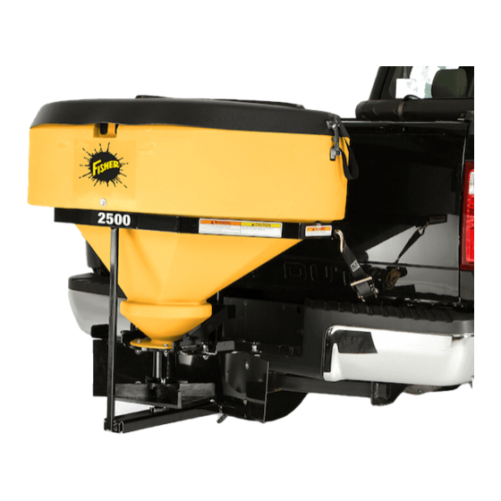
Low-Profi le Tailgate Spreader
96050-2
Model 2500
Owner's Manual
Original Instructions
CAUTION
Read this manual before installing or
operating the spreader.
This manual is for FISHER
Model 2500 Low-Profi le Tailgate Spreaders with serial numbers
®
beginning with 110816 and higher.
This manual supersedes all editions with an earlier date.
Advertisement
Table of Contents

Related Manuals for Fisher 2500


Summary of Contents for Fisher 2500
- Page 1 Original Instructions CAUTION Read this manual before installing or operating the spreader. This manual is for FISHER Model 2500 Low-Profi le Tailgate Spreaders with serial numbers ® beginning with 110816 and higher. This manual supersedes all editions with an earlier date.
-
Page 3: Spreader Owner Data Sheet
SPREADER OWNER DATA SHEET Register your spreader online at www.fi sherplows.com Owner Name: ______________________________________________________________________________ Date Purchased: ____________________________________________________________________________ Dealer Name: ______________________________________________ Phone: _________________________ Dealer Address: _____________________________________________________________________________ Vehicle Model/Year: _________________________________________________________________________ Spreader Type/Size (Model): _________________________________________ Weight: ______________ lb/kg Spreader Serial Number:______________________________________________________________________ Lit. No. 96473, Rev. 00 August 15, 2011... -
Page 5: Table Of Contents
TABLE OF CONTENTS SPREADER OWNER DATA SHEET ......3 Adjusting the Defl ector ........15 PREFACE ..............6 Variable Speed (PWM) Control......16 SAFETY INFORMATION ..........7 Starting and Stopping the Motor ....16 Safety Defi nitions ..........7 Adjusting the Spinner Speed ......16 Safety Precautions .......... -
Page 6: Preface
PREFACE This manual has been prepared to acquaint you with When service is necessary, bring your spreader to the safety information, operation and maintenance of your local dealer. They know your spreader best and your new spreader. Please read this manual carefully are interested in your complete satisfaction. -
Page 7: Safety Information
SAFETY INFORMATION SAFETY DEFINITIONS CAUTION If rear directional, CHMSL light or brake WARNING stoplights are obstructed by the spreader, Indicates a potentially hazardous situation the lights shall be relocated, or auxiliary that, if not avoided, could result in death or directional or brake stoplights shall be serious personal injury. -
Page 8: Fuses
SAFETY INFORMATION FUSES VENTILATION The electrical system contains automotive blade-style WARNING fuses. If a problem should occur and fuse replacement Vehicle exhaust contains lethal fumes. is necessary, the replacement fuse must be of the Breathing these fumes, even in low same type and amperage rating as the original. -
Page 9: Torque Chart
SAFETY INFORMATION TORQUE CHART CAUTION Read instructions before assembling. Fasteners should be fi nger tight until instructed to tighten according to torque chart. Use standard methods and practices when attaching spreader including proper personal protective safety equipment. Recommended Fastener Torque Chart (ft-lb) Torque Size... -
Page 10: Warning And Caution Labels
SAFETY INFORMATION WARNING/CAUTION LABELS Please become familiar with the Warning and Caution labels on the spreader. NOTE: If labels are missing or cannot be read, see your sales outlet. Warning Label Warning/Caution Label Lit. No. 96473/96474, Rev. 00 August 15, 2011... -
Page 11: Serial Number Label
SAFETY INFORMATION SERIAL NUMBER LABEL Code Defi nition 2-Digit Year 2-Digit Month 2-Digit Day 2-Digit Location Code ############################## XXXX 4-Digit Sequential Number ZZZZZ 5-Digit Assembly PN YYMMDDLLXXXXZZZZZ YYMMDDLLXXXXZZZZZ Lit. No. 96473/96474, Rev. 00 August 15, 2011... -
Page 12: Loading
LOADING This manual covers vehicles that have been WARNING recommended for carrying the spreader. Please see Overloading could result in an accident or your local dealer for proper vehicle applications. damage. Do not exceed GVWR or GAWR ratings as found on the driver-side vehicle CERTIFICATION door cornerpost. -
Page 13: Mounting The Spreader
MOUNTING THE SPREADER RECEIVER MOUNT SPREADER ANTI-WOBBLE CLAMP INSTALLATION 1. Place the U-bolt over the drawbar. Slide the U-bolt CAUTION tight to the truck hitch. During removal or mounting, securely grip Hitch spreader to avoid dropping. Insert Truck NOTE: The spreader shall be installed according U-Bolt Hitch to instructions supplied. -
Page 14: Operating The Spreader
OPERATING THE SPREADER DRIVING AND SPREADING ON SNOW Here are some tips for driving in these conditions: AND ICE • Drive defensively. • Do not drink, then drive or spread ice control CAUTION materials. Drinking and then driving or spreading is •... -
Page 15: Adjusting The Defl Ector
OPERATING THE SPREADER ADJUSTING THE DEFLECTOR WARNING Before making any adjustments to the Spread pattern, pattern width and the amount of defl ector settings, turn the spreader OFF. Wait material dispensed are dependent on the spinner for all conveyor or spinner movement to stop. speed and defl... -
Page 16: Variable Speed (Pwm) Control
OPERATING THE SPREADER There are two control options. They include the Variable 2. Turning the speed dial counterclockwise will Speed (PWM) Control and the ON/OFF Control. decrease the speed. VARIABLE SPEED (PWM) CONTROL Blast/Maximum Speed ON/Maximum Diagnostic 1. Press and hold the START/BLAST button as long Speed Button Indicator Light as maximum speed is needed. -
Page 17: On/Off Control
OPERATING THE SPREADER ON/OFF CONTROL Blast/Maximum Speed Move and hold the power switch to the "BLAST" Spinner Indicator Light position for as long as maximum speed is needed. (Illuminated light indicates When released, the switch will automatically return to power to the motor.) the "OFF"... -
Page 18: Removing The Spreader
REMOVING THE SPREADER REMOVING THE RECEIVER MOUNT SPREADER CAUTION During removal or mounting, securely grip spreader to avoid dropping. 1. Unplug the spreader harness from the vehicle harness. 2. Remove the receiver clamp, if installed. 3. Release and remove the ratchet straps. 4. -
Page 19: Maintenance
MAINTENANCE 6. Check the condition of the spinner disk. If the CAUTION vanes are excessively worn the unit may not Disconnect electric power at spreader spread as intended. Replace the spinner if electrical wiring harness connection and tag necessary. out if required before servicing or performing maintenance. -
Page 20: Drive Belt Replacement
MAINTENANCE DRIVE BELT REPLACEMENT RECYCLE Disconnect the electrical plug between the spreader When your spreader has performed its useful life, and truck before drive belt replacement. the majority of its components can be recycled as steel. Gear oil shall be disposed of according to local regulations. -
Page 21: 4-Pin Harness Wiring Diagram
4-PIN HARNESS WIRING DIAGRAM - LOW-PROFILE SPREADERS Cab Control White Connector Two Way Molded Connector 6 amp Fuse Red Connector 14 ga Red 8 ga Red 8 ga Red To Vehicle Ignition (Accessory Wire or 30 amp Fuse Fuse Box) 10 ga Red 14 ga Black 8 ga Black... -
Page 22: Troubleshooting Guide
TROUBLESHOOTING GUIDE For control operation and use of diagnostic indicator lights, locate the section for your control style in the Operating the Spreader section of this manual. Problem Possible Cause Suggested Solution 1. Control connector plug is loose. 1. Check plug connection at cab control. 2. - Page 23 TROUBLESHOOTING GUIDE Problem Possible Cause Suggested Solution Unplug the spreader harness and tag out, if required, before performing any of the following repairs. 1. Obstruction is preventing rotation. 1. Clear obstruction. 2. Drive belt is loose or damaged. 2. Adjust tension or replace belt if worn or Spinner does not turn.
- Page 24 Fisher Engineering reserves the right under its product improvement policy to change construction or design details and furnish equipment when so altered without reference to illustrations or specifi cations used. Fisher Engineering or the vehicle manufacturer may require or recommend optional equipment for spreaders. Do not exceed vehicle ratings with a spreader. Fisher Engineering offers a limited warranty for all spreaders and accessories.
Need help?
Do you have a question about the 2500 and is the answer not in the manual?
Questions and answers