Table of Contents
Advertisement
Fisher Engineering
50 Gordon Drive, Rockland, Maine 04841-2139 • www.fisherplows.com
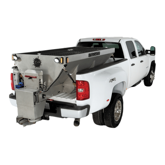
STEEL‑CASTER™ Hopper Spreader
With Gasoline Engine or Dual Hydraulic Drive
This manual is for FISHER
This document supersedes all editions with an earlier date.
Installation Instructions
CAUTION
Read this document before installing or
operating the spreader.
STEEL-CASTER Hopper Spreaders with serial numbers
®
beginning with 170711 and higher.
99002‑1, 99003‑1, 99004‑1
99006‑1, 99007‑1, 99008‑1
99010‑1 through 99018‑1
November 1, 2017
Lit. No. 43766, Rev. 01
Advertisement
Table of Contents

Related Manuals for Fisher STEEL-CASTER


Summary of Contents for Fisher STEEL-CASTER
- Page 1 With Gasoline Engine or Dual Hydraulic Drive Installation Instructions CAUTION Read this document before installing or operating the spreader. This manual is for FISHER STEEL-CASTER Hopper Spreaders with serial numbers ® beginning with 170711 and higher. This document supersedes all editions with an earlier date.
-
Page 3: Safety Information
SAFETY INFORMATION SAFETY DEFINITIONS WARNING/CAUTION LABELS Become familiar with and inform users about the WARNING warning and caution labels on the spreader. Indicates a potentially hazardous situation that, if not avoided, could result in death or NOTE: If labels are missing or cannot be read, see serious personal injury. -
Page 4: Safety Precautions
SAFETY INFORMATION SAFETY PRECAUTIONS CAUTION • Do not operate a spreader in need of Improper installation and operation could cause maintenance. personal injury and/or equipment and property damage. • Before operating the spreader, reassemble Read and understand labels and the owner's manual any parts or hardware removed for cleaning before installing, operating or making adjustments. -
Page 5: Torque Chart
SAFETY INFORMATION FIRE AND EXPLOSION NOISE Airborne noise emission during use is below 70 dB(A) WARNING for the spreader operator. Gasoline is highly flammable and gasoline vapor is explosive. Never smoke while VIBRATION working on vehicle. Keep all open flames away from gasoline tank and lines. -
Page 6: Load Volume
LOADING CERTIFICATION This document covers vehicles that have been recommended for carrying the hopper spreader. Please see your local dealer for proper vehicle applications. WARNING New untitled vehicle installation of a spreader WARNING requires National Highway Traffic Safety Administration altered vehicle certification Overloading could result in an accident or labeling. -
Page 7: Mounting The Spreader
MOUNTING THE SPREADER INSTALL TOP SCREEN BRACKETS NOTE: Periodically throughout the snow and ice control season, verify that mounting devices 1. Install a top screen bracket at each end of are secure. the spreader cross beams using the supplied 1/4" x 3/4" carriage bolts, 1/4" washers, and INSTALL INVERTED V 1/4"... - Page 8 MOUNTING THE SPREADER INSTALL HOPPER IN TRUCK BED CAUTION Before drilling holes, check to be sure that no 1. Remove the vehicle tailgate. vehicle wiring or other components could be damaged. 2. Remove the wood rails from the hopper legs. 5.
- Page 9 MOUNTING THE SPREADER Sill Spacer WARNING Spreader shall be bolted to vehicle frame. Measure the distance from the front end of the hopper Do not rely on the tie‑down chains or straps sill to the front of the truck bed and make a spacer alone to hold spreader in vehicle.
- Page 10 MOUNTING THE SPREADER CHUTE INSTALLATION—GAS MODELS Changing Long Chute to Short Configuration A short spinner shaft is shipped with the 9' and Chute Length Adjustment 10' hoppers so the chute can be reconfigured if necessary. The chute must be separate from the The material chute for hopper spreaders with gasoline hopper for this procedure.
- Page 11 MOUNTING THE SPREADER Install Chute to Spreader —Gas Models c. Slide the spinner shaft out of the chute. Remove the sprocket and key from the top of the shaft by loosening the sprocket set screw. 1. Unlatch the access door on both sides. Lift the door and slide it inward to hold it open.
- Page 12 MOUNTING THE SPREADER 5. Using a straight edge, check the alignment of the 5. Loosen the tensioner adjustment bolt jam nut and spinner shaft and spinner drive sprockets. advance the adjustment bolt until it contacts the tensioner pivot bolt nut. This will keep the pivot bolt from moving.
- Page 13 MOUNTING THE SPREADER CHUTE INSTALLATION—HYDRAULIC Changing Long Chute to Short Configuration MODELS A short spinner shaft is shipped with the 9' and 10' hoppers so the chute can be reconfigured if Chute Length Adjustment necessary. The chute must be separate from the hopper for this procedure.
-
Page 14: Tie-Down Straps
MOUNTING THE SPREADER Install Chute to Spreader—Hydraulic c. Remove the spinner bolt. Set the bolt and spinner aside. Models 1. Pick up the chute from each side and slide the Spinner chute‑side hinges over the hopper‑side hinges. Bolt Two people are recommended for this step. 2. - Page 15 WIRING AND HARNESS INSTRUCTIONS WIRING INSTRUCTIONS—GAS MODELS The shaded portions in the illustration below show the most commonly restricted areas. All spreaders are shipped from the factory with the CAUTION spreader harness wired to the engine, clutch, and electric throttle. Do not alter, modify or install additional components in shaded areas shown below.
- Page 16 WIRING AND HARNESS INSTRUCTIONS CENTER HIGH‑MOUNTED STOPLIGHT ACCESSORY LICENSE PLATE LIGHT (CHMSL)—GAS & HYDRAULIC MODELS If the accessory License Plate Light Kit is not installed, coil and cable‑tie the brown wire away from An LED center high‑mounted stoplight is standard equipment on all stainless steel hopper spreaders.
- Page 17 VEHICLE HARNESS WIRING DIAGRAM Gas Models Choke ON Light Light (Red) (Green) Clutch Switch Start Switch Choke Switch WHT/ To vehicle CHMSL signal Cab Control (tap located in cab) Wiring To Switched Violet wire provided ( + ) Accessory Circuit for accessory use.
-
Page 18: Choke Adjustment
CHOKE ADJUSTMENT—GASOLINE ENGINE CHOKE ADJUSTMENT 4. Attempt to move the choke rod in the direction of the choke adjusting screw. If the rod has no (HONDA ENGINES ONLY) movement, no adjustment is necessary. 1. Engines are shipped with choke adjusted to the 5. -
Page 19: Hydraulic Unit Installation
HYDRAULIC UNIT INSTALLATION Hydraulic Unit Installation Cab Control Valve Installation Recommended installation sequence: 1. With the seat fully forward, select a suitable location to mount the cab control valve, allowing 1. Install the pump (not provided). for the operator to adjust the control and to turn it ON and OFF. -
Page 20: Dual Hydraulic Circuit Diagram
DUAL HYDRAULIC CIRCUIT DIAGRAM Typical Hydraulic Circuit Dedicated Fixed Displacement Pump PUMP 23 gal/min @ 1500 psi VALVE Rated to 40 gal/min @ 1500 psi Controlled Flow to Conveyor Motor: 10 gal/min @ 1500 psi Inlet Flow from Tank Excess Flow Optional Dual Drive Circuit, toTank Controlled Flow to... -
Page 21: Final Adjustments
FINAL ADJUSTMENTS DRIVE CHAIN AND SPINNER CHAIN— CONVEYOR PINTLE CHAIN TENSION GAS MODELS Check the conveyor chain tension by confirming that the chain is visible in the chain tension port. If the • Verify that the drive sprocket set screws and the chain is too tight, it will be above the port;... -
Page 22: Final Checklist
FINAL ADJUSTMENTS FINAL CHECKLIST Gas Models All Models Verify correct engine oil level. (See the engine Verify that the gear case oil level is level with the manufacturer's owner's manual.) fill hole. Verify correct engine‑to‑clutch sprocket alignment ... - Page 24 Fisher Engineering or the vehicle manufacturer may require or recommend optional equipment for spreaders. Do not exceed vehicle ratings with a spreader. Fisher Engineering offers a limited warranty for all spreaders and accessories. See separately printed page for this important information. The following are registered ( ) or unregistered (™)
Need help?
Do you have a question about the STEEL-CASTER and is the answer not in the manual?
Questions and answers