3Ware 9650SE Installation Manual
Serial ata raid controller
Hide thumbs
Also See for 3ware 9650SE:
- User manual (361 pages) ,
- Manual (150 pages) ,
- Cli manual (103 pages)
Table of Contents
Advertisement
Quick Links
- 1 9650Se Raid Controller Card Models
- 2 Chapter 2. Installing Your 3Ware Raid Controller
- 3 Step 1 (9650Se-2Lp). Connect the Cables to the Controller
- 4 Step 2. Install the Controller in the Computer
- 5 Step 6. Configure Your Raid Arrays
- 6 Step 5. Finishing up the Raid Controller Installation
- 7 Chapter 3. Installing the Battery Backup Unit
- Download this manual
Advertisement
Table of Contents

Subscribe to Our Youtube Channel
Related Manuals for 3Ware 3ware 9650SE


Summary of Contents for 3Ware 3ware 9650SE
- Page 1 ® 3ware 9650SE Serial ATA RAID Controller PN 720-0147-00 October 2006...
- Page 2 All other purposes require the express written consent of AMCC, 215 Moffett Park Drive, Sunnyvale, CA 94089. AMCC shall not be responsible or liable for, and shall be held harmless against, any and all damages, claims, and/or disputes that arise from the copying or reproduction of this publication.
-
Page 3: Table Of Contents
Table of Contents About this Guide ........iv Chapter 1. -
Page 4: About This Guide
User Guide and the CLI Guide. Online help is also available when you are using 3DM 2 (3ware Disk Manager). Additional support information is available in the 3ware Knowledgebase, at this website: http://www.3ware.com/KB 3ware 9650SE Serial ATA RAID Controller Installation Guide... -
Page 5: Chapter 1. Getting Started
(RAID 6 and RAID 50 are available only with 3ware RAID controller models that have 8 or more ports) PCI Express® x1, x4, and x8 connectivity Contents of this Package This document, 3ware 9650SE Serial ATA RAID Controller Installation Guide 3ware CD-ROM with driver, software, and additional documentation... -
Page 6: System Requirements
Drives must meet SATA-1 (1.5 Gb/s) or SATA-2 (3.0 Gb/s) standards. Drives may be of any capacity or physical form factor. A list of tested drives is available at http://www.3ware.com/products/ compatibility_sata2.asp 3ware 9650SE Serial ATA RAID Controller Installation Guide... - Page 7 System Requirements Shielded and unshielded interface cables for Serial ATA Note: controllers may not exceed 1M (39”) in length. Operating System Requirements Windows 2000, Windows XP, Windows Server 2003, both 32- bit and 64-bit x86 Red Hat Linux, 32-bit and 64-bit x86 SuSE Linux, 32-bit and 64-bit x86 Fedora Core, 32-bit and 64-bit x86 Other versions of Linux, 32-bit and 64-bit x86, using the open...
-
Page 8: 9650Se Raid Controller Card Models
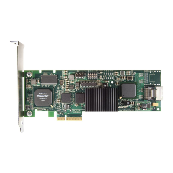
Chapter 1. Getting Started 9650SE RAID Controller Card Models Figure 1. 2-Port 3ware 9650SE-2LP Serial ATA RAID Controller Heat Sink LED Connector Ports: 0 (on top) 1 (on the bottom) Figure 2. 4-Port 3ware 9650SE-4LPML Serial ATA RAID Controller C connector... - Page 9 9650SE RAID Controller Card Models Figure 3. 8-Port 3ware 9650SE-8LPML Serial ATA RAID Controller Heat Sink C connector Connectors Ports: 4 thru 7 0 thru 3 Slots for battery BBU connector and hole for post Figure 4. 12-Port 3ware 9650SE-12ML Serial ATA RAID Controller...
-
Page 10: Cables
Chapter 1. Getting Started Figure 5. 16-Port 3ware 9650SE-16ML Serial ATA RAID Controller LED Connectors Heat sink C connector Ports: 12 thru 15 8 thru 11 4 thru 7 0 thru 3 Holes for BBU connector and hole for post... - Page 11 Cables Multilane breakout cables For use with a backplane that has individual SATA connectors or individual serial ATA drives, multilane breakout cables have an SFF-8087 multilane connector on one end and four individual SATA connectors on the other end. This is the type of cable that ships with the 3ware Note: 9650SE multilane controllers.
-
Page 12: Safety Information
Chapter 1. Getting Started Multilane converter cables To connect from a 3ware 9650SE multilane RAID controller to a chassis that has SFF-8470 connectors on the backplane, use multilane converter cables, which have a SFF-8087 connector on one end and an Infini-band SFF8470 connector on the other. - Page 13 Protecting Equipment and Data Heat Sink Warning. Do not replace the factory-installed heat sink shipped with the 3ware 9650SE RAID controller. Replacing the heat sink will alter thermal characteristics and cooling requirements and may cause the controller to fail. Replacing the factory-installed heat sink will void the warranty.
-
Page 14: Installation Considerations
Air Flow, Cable Length, and Routing Space Adequate airflow and ventilation are particularly important for 3ware 9650SE RAID controllers. The on-board heat sink collects heat, and must have adequate airflow in order to disburse it. It is important that the cables do not obstruct the air flow or prevent proper ventilation of the system. - Page 15 Most chassis have a single drive activity cable that you can connect to the overall activity indicator on the 3ware 9650SE controller. For the location of the overall drive activity connector, see the figure for the appropriate controller on page 20 and 22, and refer to Table 2, “LED Indicator Pin Positions,”...
- Page 16 Be careful when installing the 3ware RAID controller into your system. Excessive force can damage the board or your system. Be sure to follow the installation instructions in “Chapter 2. Installing Your 3ware RAID Controller” on page 13. 3ware 9650SE Serial ATA RAID Controller Installation Guide...
-
Page 17: Chapter 2. Installing Your 3Ware Raid Controller
An ESD grounding strap or mat A Phillips screwdriver Before You Start 3ware 9650SE RAID controllers can be installed in a standard enclosure or in an enclosure with a backplane. Be sure to read “Safety Information” on page 8 in Chapter 1. -
Page 18: Step 1 (9650Se-2Lp). Connect The Cables To The Controller
Port 0 is on top. Port 1 is on the bottom Repeat steps 2 and 3 for the second SATA cable. (You connect one cable for each hard drive you will attach.) 3ware 9650SE Serial ATA RAID Controller Installation Guide... -
Page 19: Step 1 (Multilane Controllers). Connect The Cables To The Controller
Step 1 (Multilane Controllers). Connect the Cables to the Controller Step 1 (Multilane Controllers). Connect the Cables to the Controller The 9650SE-4LPML, 9650SE-8LPML, 9650SE-12ML, and 9650SE-16ML models are all multilane controllers. (For the 9650SE-2LP, turn to the previous page.) Take out the multilane cables provided with your controller. Connect each multilane cable to a multilane connector on the controller. -
Page 20: Step 2. Install The Controller In The Computer
PCI Express slot pins when pushed into place. Only the 3ware 9650SE-2LP RAID controller will fit in a one lane (x1) PCI Express slot. The 4-port and 8-port cards will work in the x4, x8, or x16 PCI Express slots, while the 12-port and 16-port cards will work in the x8 or x16 PCI Express slots. - Page 21 Press down gently on the edge of the 3ware RAID controller directly above the PCI Express slot until it is fully seated. Figure 11. Inserting Controller Into PCI Express Slot Use a PCI Express slot for the 3ware 9650SE controller. Do NOT use a PCI-X slot.
-
Page 22: Step 3 (9650Se-2Lp). Connect The Cables To The Drives
3ware RAID Controller and plug it into the drive or drive carrier. One edge of each SATA cable connector is keyed to ensure proper installation. Figure 12. SATA Cable Connecting to Drive 3ware 9650SE Serial ATA RAID Controller Installation Guide... -
Page 23: Step 3 (Multilane Controllers). Connect The Cables To The Drives Or
Step 3 (Multilane Controllers). Connect the Cables to the Drives or Back- Step 3 (Multilane Controllers). Connect the Cables to the Drives or Backplane For the 9650SE-4LPML, 9650SE-8LPML, 9650SE-12ML, and 9650SE-16ML models, follow the steps below. (For the 9650SE- 2LP, turn to the previous page.) If your drives are not already installed, install them now, either by attaching them to the backplane, or by installing them in the computer chassis. -
Page 24: Step 4. Connecting Drive Activity Led Indicators (Optional)
Figure 14 through Figure 18 show the location of LED indicators on the different 9650SE controllers. Additional detail about these connectors starts on page 23. Figure 14. 2-Port 3ware 9650SE-2LP Serial ATA RAID Controller LED indicators for individual Overall LED drive status indicator: drives on J7: 0 and 1 (left to the last two pins of J7. - Page 25 Step 4. Connecting Drive Activity LED Indicators (Optional) Figure 15. 4-Port 3ware 9650SE-4LPML Serial ATA RAID Controller Overall LED drive status indicator: LED indicators for individual the last two pins of J7. The anode drives on J7: 0, 1, 2, 3...
- Page 26 Chapter 2. Installing Your 3ware RAID Controller Figure 17. 12-Port 3ware 9650SE-12ML Serial ATA RAID Controller Overall LED drive status indicator is the LED indicators for individual drives right-most LED header pin pair on each J7 is for drives 0, 1, 2, 3 (left to right) LED connector (J7, J8, and J9).
- Page 27 Step 4. Connecting Drive Activity LED Indicators (Optional) Additional Details About the LED Status Connectors As shown in Figure 15 through Figure 18, LED connectors for individual drives are on J7, J8, J9, and J1 for the 16 port card, on J7, J8, and J9 for the 12-port cards, and on J7 and J8 for the 8-port, and J7 for the 2-port and 4-port cards.
- Page 28 If using a chassis that has a common or shared LED ground, be sure to only connect LED cables to the anode pins on the controller. Do not connect any common ground to any cathode pins on the controller. 3ware 9650SE Serial ATA RAID Controller Installation Guide...
-
Page 29: Step 5. Finishing Up The Raid Controller Installation
Step 5. Finishing Up the RAID Controller Installation Step 5. Finishing Up the RAID Controller Installation After you have installed the controller in the computer and attached appropriate cables to the controller and drives, complete the following steps to complete the hardware installation. Check Installation and Close the Case Verify that the cables do not interfere with the operation of any other components in the case or block the flow of cooling air. -
Page 30: Chapter 3. Installing The Battery Backup Unit
Battery Backup Unit The Battery Backup Unit (BBU) is an add-on that can be attached to a 3ware 9650SE RAID controller to supply power to the memory module from an attached battery pack in the event of a system power loss. This allows the controller to use write-caching for optimal performance and not be exposed to data loss in the event of a system power failure. -
Page 31: Tools And Equipment Required
Tools and equipment required Slot-head screwdriver Grounding strap Battery Backup Unit (BBU) and battery 3ware 9650SE series controller Installation Overview The Battery Backup Unit (BBU) is comprised of two pieces: the battery module and the BBU control module. These pieces attach to the controller at the points illustrated in... - Page 32 Slots for the clips b) BBU receptacle c) Hole for post Figure 21. Points of connection on the full-height controller a) Hole and slots for the clips c) Hole for post b) BBU receptacle 3ware 9650SE Serial ATA RAID Controller Installation Guide...
-
Page 33: Installation Instructions
Installation Instructions Installation Instructions Remove the screw head from the plastic post on the BBU control module and set it aside (you will reattach it soon.) Figure 22. Removing the head from the plastic post Position the BBU control module above the controller and align the BBU control module and the controller, making sure to: Mate the connector on the BBU control module with the receptacle on the controller. - Page 34 When the plastic post and the connector are attached correctly, the module is in the correct orientation. 3ware 9650SE Serial ATA RAID Controller Installation Guide...
- Page 35 Installation Instructions If you have a 4-port or 8-port 9650SE: Hook the clips on the top of the battery module over the slots on the top edge of the controller. Figure 25. Clips on the battery module hook over slots on the top edge of the half-height controller Figure 26.
- Page 36 Figure 28. Attaching the battery module to the full-height controller Press down gently on the battery module until the bottom clip snaps into place in the lower hole. 3ware 9650SE Serial ATA RAID Controller Installation Guide...
- Page 37 Installation Instructions Insert the battery power connector into the power receptacle on the BBU. Note: The battery will drain if it is plugged in and there is no power to the unit. If the system will not be used right away, wait to do this step until the system is ready for use.
-
Page 38: Replacing The Battery
While pressing down on the top of the battery module, lift out the bottom of the battery module slightly. Once the bottom of the module is free, slide the module up to release the clips on the top. 3ware 9650SE Serial ATA RAID Controller Installation Guide... - Page 39 Replacing the Battery Figure 30. Removing the battery module a) Push the battery module down gently. b) Lift out the bottom of the battery module to release the clip on the bottom edge. c) Lift up to remove the clips on the top edge.
- Page 40 You can run the battery test from the BBU page of either 3BM or 3DM 2, or by using the 3ware CLI. For detailed instructions, see the 3ware Serial ATA RAID Controller User Guide and the 3ware Serial ATA RAID Controller CLI Guide. 3ware 9650SE Serial ATA RAID Controller Installation Guide...
-
Page 41: Appendix: Technical Support
For specific answers to questions or to give feedback about the product, visit our Web site at http://www.3ware.com/support log in. AMCC also offers toll-free 1 (800) 840-6055 or 1 (408) 542- 8800 direct phone support during normal business hours. Sales and ordering information For sales information, send an electronic mail message to 3wareSales@amcc.com.
Need help?
Do you have a question about the 3ware 9650SE and is the answer not in the manual?
Questions and answers