Table of Contents
Advertisement
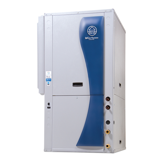
500A11
Geothermal Heat Pump
• R-410A Refrigerant
• 1, 1.5, 2, 2.5, 3, 3.5, 4, 5, 6 Ton Single Speed
• 2, 3, 4, 5, 6 Ton Dual Capacity
Installation Information
ormation
Water Piping Connections
onnections
Hot Water Generator Connections
erator Connections
Electrical
Startup Procedures
ures
Troubleshooting
g
Preventive Maintenance
ntenance
C
US
IM2500AN 02/13
Advertisement
Table of Contents

Related Manuals for Water Furnace 500A11 5 Series


Summary of Contents for Water Furnace 500A11 5 Series
- Page 1 500A11 Geothermal Heat Pump • R-410A Refrigerant • 1, 1.5, 2, 2.5, 3, 3.5, 4, 5, 6 Ton Single Speed • 2, 3, 4, 5, 6 Ton Dual Capacity Installation Information ormation Water Piping Connections onnections Hot Water Generator Connections erator Connections Electrical Startup Procedures...
-
Page 3: Table Of Contents
5 SERIES 500A11 INSTALLATION MANUAL Table of Contents Model Nomenclature ............4 General Installation Information . -
Page 4: Model Nomenclature
5 SERIES 500A11 INSTALLATION MANUAL Model Nomenclature Model Type IntelliStart Options N = 5 Series Water-to-Air N = None A = IntelliStart (022-072) Compressor Type D = Dual Capacity Controls Options S = Single Speed A = Aurora Base Control (ABC) B = Aurora Advanced Control Cabinet Configuration (ABC and AXB) -
Page 5: General Installation Information
5 SERIES 500A11 INSTALLATION MANUAL General Installation Information Safety Considerations Filter Rack Conversion A 2 in. MERV 11 filter is shipped with the heat pump. To WARNING: Before performing service or field convert the filter rack to use 1 in. filters, simply insert maintenance operations on a system, turn off main the provided plastic push pins into the holes located in the power switches to the indoor unit. -
Page 6: Installing Horizontal Units
5 SERIES 500A11 INSTALLATION MANUAL General Installation Information cont. the position shown in Figure 3. The unit should be pitched Installing Horizontal Units approximately 1/4-inch towards the drain in both directions Remove and discard the compressor hold down shipping to facilitate the removal of condensate. Use only the bolts bolt located at the front of the compressor mounting provided in the kit to attach hanger brackets. - Page 7 5 SERIES 500A11 INSTALLATION MANUAL General Installation Information cont. Figure 3: Hanger Location and Assembly Hanger Dimensions Weight Distribution Unit Hanger Dimensions Horizontal Weight Distribution Hanger Kit Model Vertical Horizontal Part Number Model Front Back Weight Weight 44.7 25.1 21.4 99S500A04 113.5 63.8...
-
Page 8: Duct System
5 SERIES 500A11 INSTALLATION MANUAL General Installation Information cont. the swivel connector prior to attempting any connection. Duct System The rubber seals are shipped attached to the waterline. An air outlet collar is provided on vertical top and rear To make the connection to a ground loop system, mate air discharge units and all horizontal units to facilitate the brass connector (supplied in CK4LI connector kit) a duct connection (vertical bottomflow units have no... -
Page 9: Water Quality
5 SERIES 500A11 INSTALLATION MANUAL General Installation Information cont. can likewise become scaled and possibly plugged. In areas Water Quality with extremely hard water, the owner should be informed In ground water situations where scaling could be heavy that the heat exchanger may require occasional flushing. or where biological growth such as iron bacteria will be present, a closed loop system is recommended. -
Page 10: Closed Loop Ground Source Systems
5 SERIES 500A11 INSTALLATION MANUAL Closed Loop Ground Source Systems NOTE: For closed loop systems with antifreeze protection, Multiple Units on One Flow Center set SW2-1 to the “LOOP” (15°F) position. (Refer to the DIP NOTE: This feature is only available in the Aurora Advanced Switch Settings table in the Aurora Control section.) Control package (AXB board), NOT the Aurora Base Control (ABC). -
Page 11: Open Loop Ground Water Systems
5 SERIES 500A11 INSTALLATION MANUAL Open Loop Ground Water Systems Typical open loop piping is shown below. Always maintain on local codes, i.e. recharge well, storm sewer, drain field, water pressure in the heat exchanger by placing water adjacent stream or pond, etc. Most local codes forbid control valves at the outlet of the unit to prevent mineral the use of sanitary sewer for disposal. -
Page 12: Hot Water Generator Connections
5 SERIES 500A11 INSTALLATION MANUAL Hot Water Generator Connections To maximize the benefits of the hot water generator a Figure 11: Typical Hot Water Generator Installation minimum 50-gallon water heater is recommended For Cold 3/4” x 3/4” x 1/2” tee W ater In Water Out higher demand applications, use an 80-gallon water... - Page 13 5 SERIES 500A11 INSTALLATION MANUAL Hot Water Generator Connections cont. Plumbing Installation Hot Water Generator Startup 1. Inspect the dip tube in the water heater cold inlet 1. Turn the hot water generator switch to the “ON” position. The hot water generator switch will allow the for a check valve.
-
Page 14: Electrical Connections
5 SERIES 500A11 INSTALLATION MANUAL Electrical Connections General Accessory Relay Be sure the available power is the same voltage and phase A set of “dry” contacts has been provided to control as that shown on the unit serial plate. Line and low voltage accessory devices, such as water solenoid valves on open wiring must be done in accordance with local codes or the loop installations, electronic air cleaners, humidifiers, etc. -
Page 15: Electronic Thermostat Installation
5 SERIES 500A11 INSTALLATION MANUAL Electrical Connections cont. Figure 14: Pump Wiring 208-230/60/1 Pump Power Wiring See Figure 14 for electrical connections from control box to pumps. FC1/FC2 style flow centers with fixed speed pumps Optional External Variable Speed Loop connect to PB1 in the control box. -
Page 16: Auxiliary Heat Ratings
5 SERIES 500A11 INSTALLATION MANUAL Auxiliary Heat Ratings Btu/h Model Size Compatibility Model Stages Min cfm 208V 230V 208V 230V 026 - 030 036 - 042 048 - 072 • EAS(H)4 9,700 12,900 EAM(H)5 12,300 16,300 • • • EAM(H)8 19,400 25,900 •... -
Page 17: Electrical Data
5 SERIES 500A11 INSTALLATION MANUAL Electrical Data Single Speed Unit with Variable Speed ECM Motor Compressor Blower Total Voltage Model Rated Voltage Pump Loop Motor Unit Circ Fuse/ Min/Max LRA** HACR 208-230/60/1 197/253 10.4 33.5 16.5 18.1 208-230/60/1 197/253 14.0 48.0 17.0 18.8... - Page 18 5 SERIES 500A11 INSTALLATION MANUAL Electrical Data cont. Dual Capacity Unit with Variable Speed ECM Motor Compressor Blower Total Rated Voltage Model Pump Loop Motor Unit Circ Fuse/ Voltage Min/Max LRA** HACR 208-230/60/1 197/253 18.2 11.6 58.3 21.0 21.4 24.4 208-230/60/1 197/253 23.8...
-
Page 19: Blower Performance Data
5 SERIES 500A11 INSTALLATION MANUAL Blower Performance Data Single Speed Unit with Variable Speed ECM Motor Airflow Speed Settings Model 1025 1125 0.50 1000 1100 1200 0.50 1000 1100 1200 0.50 1000 1100 1200 1300 1400 1500 1550 0.50 1000 1100 1300 1500... - Page 20 5 SERIES 500A11 INSTALLATION MANUAL Blower Performance Data cont. Setting Blower Speed - ECM ECM Speed Setup - These screens allow the technician to select the “G”, low, high, and auxiliary heat blower speed for The ABC board’s Yellow Config LED will flash the current the ECM blower motor.
- Page 21 5 SERIES 500A11 INSTALLATION MANUAL Blower Performance Data cont. Single Speed Unit with 5-Speed ECM Motor Motor Motor T’stat Blower Motor Airflow (cfm) at External Static Pressure (in. wg) Model Speed Cnct. Size 0.05 0.10 0.15 0.20 0.25 0.30 0.35 0.40 0.45 0.50 0.60 0.70 0.80 0.90 1.00 High Med High 9 x 7...
- Page 22 5 SERIES 500A11 INSTALLATION MANUAL Blower Performance Data cont. Dual Capacity Unit with 5-Speed ECM Motor Motor T’stat Blower Motor Airflow (cfm) at External Static Pressure (in. wg) Model Speed Cnct. Size 0.05 0.10 0.15 0.20 0.25 0.30 0.35 0.40 0.45 0.50 0.60 0.70 0.80 0.90 1.00 High 1120 1109 1097 1082 1066 1055 1044 1028...
- Page 23 5 SERIES 500A11 INSTALLATION MANUAL Blower Performance Data cont. Unit with Standard PSC Motor Motor Blower Motor Airflow (cfm) at External Static Pressure (in. wg) Model Size 0.05 0.10 0.15 0.20 0.25 0.30 0.35 0.40 0.45 0.50 0.60 0.70 0.80 0.90 1.00 6 x 8...
-
Page 24: Dimensional Data
5 SERIES 500A11 INSTALLATION MANUAL Vertical Dimensional Data Top Air Discharge LEFT RETURN RIGHT RETURN 1.9in [4.8cm] 1.9in [4.8cm] K J I D E H F FRONT 2ft [61cm] Primary Service Access RIGHT SIDE LEFT SIDE Electrical Return Connection Connections Discharge Connection Overall Cabinet Water Connections... - Page 25 5 SERIES 500A11 INSTALLATION MANUAL Vertical Dimensional Data cont. Bottom Air Discharge LEFT RETURN RIGHT RETURN 1.70 (4.3 cm) LEFT SIDE RIGHT SIDE 1.90 (4.7 cm) FRONT 2ft [61cm] Primary Service Access LEFT BOTTOM DISCHARGE RIGHT BOTTOM DISCHARGE FLOOR FOOT PRINT FLOOR FOOT PRINT Electrical Water Connections...
- Page 26 5 SERIES 500A11 INSTALLATION MANUAL Vertical Dimensional Data cont. Rear Air Discharge 1.90 1.90 FRONT REAR VIEW SIDE VIEW SIDE VIEW REAR VIEW LEFT RETURN LEFT RETURN RIGHT RETURN RIGHT RETURN Electrical Return Connection Discharge Connection Overall Cabinet Water Connections Connections using std deluxe filter duct flange installed (±0.10 in)
-
Page 27: Horizontal Dimensional Data
5 SERIES 500A11 INSTALLATION MANUAL Horizontal Dimensional Data TOP VIEW 2.1in [5.4cm] MOUNT (2) HANGER BRACKETS AS SHOWN TO ALLOW ACCESS TO FILTER 2ft [61cm] Primary Service Access FRONT VIEW SIDE DISHCARGE VIEW END VIEW 1.9in [4.8cm] D E F G K J I AS SHOWN LR UNIT (RR UNIT ON OPPOSITE SIDE—SAME DIMENSIONS) Electrical... -
Page 28: Physical Data
5 SERIES 500A11 INSTALLATION MANUAL Physical Data Single Speed Single Speed Model Compressor (1 each) Rotary Scroll Factory Charge R-410A, oz [kg] Vertical 42 [1.19] 40 [1.13] 62 [1.76] 80 [2.26] 84 [2.38] 92 [2.60] 100 [2.83] 120 [3.40] 150 [4.25] Factory Charge R-410A, oz [kg] Horizontal 42 [1.19]... - Page 29 5 SERIES 500A11 INSTALLATION MANUAL Physical Data cont. Dual Capacity Dual Capacity Model Compressor (1 each) Copeland UltraTech, Dual Capacity Scroll Factory Charge R-410A, oz [kg] Vertical 60 [1.70] 82 [2.32] 93 [2.63] 128 [3.63] 138 [3.91] Factory Charge R-410A, oz [kg] Horizontal 60 [1.70] 82 [2.32]...
-
Page 30: The Aurora™ Control System
5 SERIES 500A11 INSTALLATION MANUAL The Aurora™ Control System Aurora ‘Base’ Control Aurora ‘Advanced’ Control The Aurora ‘Advanced’ The Aurora ‘Base’ Control Control expands on (ABC) System is a complete the capability of the residential and commercial Aurora ‘Base’ Control comfort system that brings (ABC) System by adding all aspects of the HVAC... - Page 31 5 SERIES 500A11 INSTALLATION MANUAL The Aurora Control System cont. Service Device Description Aurora ‘Base’ Aurora ‘Advanced’ Allows setup, monitoring and troubleshooting of any Aurora Control. NOTE: Although the ABC has basic compatibility with all For Service For Service Aurora, new product features may not be available on older (Ver.
-
Page 32: Control Features
5 SERIES 500A11 INSTALLATION MANUAL The Aurora ‘Base’ Control System cont. Aurora ‘Base’ Control Field Selectable Options via Hardware DIP Switch (SW1) – Test/Configuration Button (See SW1 Operation Table) Test Mode The control is placed in the test mode by holding the push button switch SW1 for 2 - 5 seconds. -
Page 33: Safety Features
5 SERIES 500A11 INSTALLATION MANUAL The Aurora ‘Base’ Control System cont. Cycle with Blower - The accessory relay will cycle with Lockout – when locked out, the blower will operate the blower output. continuously in “G” speed, and PSC blower motor output will remain on. - Page 34 5 SERIES 500A11 INSTALLATION MANUAL The Aurora ‘Base’ Control System cont. Over/Under Voltage Shutdown - An over/under voltage Cooling Operation condition exists when the control voltage is outside the In all cooling operations, the reversing valve directly tracks range of 18 VAC to 30 VAC. If the over/under voltage the O input.
- Page 35 5 SERIES 500A11 INSTALLATION MANUAL The Aurora ‘Base’ Control System cont. Aurora ‘Base’ Control LED Displays Aurora Interface and Diagnostics (AID) Tool These three LEDs display the status, configuration, and The Aurora Interface and fault codes for the control. These can also be read in plain Diagnostics (AID) Tool is English via the Aurora AID Tool.
-
Page 36: Aurora Advanced Control System
5 SERIES 500A11 INSTALLATION MANUAL The Aurora ‘Advanced’ Control System the current thermostat demand cycle. Since compressor hot Aurora ‘Advanced’ Control Features gas temperature is dependent on loop temperature in cooling The Aurora ‘Advanced’ mode, loop temperatures may be too low to allow proper Control system expands on heating of water. - Page 37 5 SERIES 500A11 INSTALLATION MANUAL The Aurora ‘Advanced’ Control System cont. Advanced Communication Ports Home Automation 2 – E24 HA2 With a closed dry contact signal, this input will cause an Communication ports P6 and P8 will provide future alarm and Alert Code 24 to indicate on the stat or flash expansion via dedicated protocols.
- Page 38 5 SERIES 500A11 INSTALLATION MANUAL The Aurora ‘Advanced’ Control System cont. Special Modes and Applications Aurora ‘Advanced’ Control LED Displays These three LEDs display the status, configuration, and 5-Speed ECM Blower Motor fault codes for the control. These can also be read in plain Normally the 5-Speed ECM motor can be driven off English via the Aurora AID Tool.
-
Page 39: Reference Calculations And Legend
5 SERIES 500A11 INSTALLATION MANUAL Reference Calculations Heating Calculations: Cooling Calculations: LWT = EWT + LWT = EWT - gpm x 500 gpm x 500 LAT (DB) = EAT (DB) - LAT = EAT + cfm x 1.08 cfm x 1.08 LC = TC - SC TH = HC + HW S/T =... -
Page 40: Wiring Schematics
5 SERIES 500A11 INSTALLATION MANUAL Wiring Schematics Aurora Advanced with ECM and IntelliStart Ext Pump Orange(9) Pump 1/2 hp Total 208-230/60/1 Pump Brown(10) NOTE 8 Variable Speed Pump Pump 208-230/60/1 See Figure 1 for DHW wiring. PRESSURE TRANSDUCER Black White REFRIGERATION OPTION Brown... - Page 41 5 SERIES 500A11 INSTALLATION MANUAL Wiring Schematics cont. Aurora Advanced with ECM and IntelliStart cont. Blue Blue Run Winding IntelliStart Violet(8) Pink Active Violet(7) Start Black Black Common BLOWER CURRENT Capacitor (16) TRANSDUCER NOTE 3 NOTE 2 (CT) Black/White(5) Brown Gray/White(4) Orange Black(3)
- Page 42 5 SERIES 500A11 INSTALLATION MANUAL Wiring Schematics cont. Aurora Advanced with 5-Speed ECM Ext Pump Orange(9) Pump 1/2 hp Total 208-230/60/1 Pump Brown(10) NOTE 10 Variable Speed Pump Pump 208-230/60/1 See Figure 1 for DHW wiring. PRESSURE TRANSDUCER Black White REFRIGERATION OPTION Brown...
- Page 43 5 SERIES 500A11 INSTALLATION MANUAL Wiring Schematics cont. Aurora Advanced with 5-Speed ECM cont. Blue Violet(8) Violet(7) Black NOTE 3 MODULATING VALVE Brown AXB BOARD Capacitor (16) Orange NOTE 2 BLOWER CURRENT Green TRANSDUCER (CT) Black/White (5) Brown 24 VAC Gray/White (4) Green 0-10DC...
- Page 44 5 SERIES 500A11 INSTALLATION MANUAL Wiring Schematics cont. Aurora Base with PSC Ext Pump 1/2 hp Total 208-230/60/1 Compressor Violet(7) Pump Pump Blue Violet(8) Black Circuit Breaker Tan(6) Black(2) Black(3) Circuit Breaker Hot Water Unit Power Supply NOTE 4 Purple NOTE 2 208-230/60/1 Limit Switch...
- Page 45 5 SERIES 500A11 INSTALLATION MANUAL Wiring Schematics cont. Aurora Base with PSC cont. Notes 208-230/60/1 208-230/60/1 Auxiliary Electric Heat Power With optional ' EA' Series Circuit 2 Circuit 1 Auxiliary Electric Heat 1 - Switch blue and red wires for 208V operation. 2 - The blk/wh and gray/wh wires are removed when Aux Heat Typical schematic shown NOTE 3...
- Page 46 5 SERIES 500A11 INSTALLATION MANUAL Wiring Schematics cont. Aurora Base with ECM and IntelliStart Blue Ext Pump 1/2 hp Total 208-230/60/1 Compressor Run Winding Violet(7) IntelliStart Blue Pump Pump Violet(8) Pink Active Start Circuit Breaker Tan(6) Black Common Black(2) Black(3) Circuit Breaker Unit Power Supply Hot Water...
- Page 47 5 SERIES 500A11 INSTALLATION MANUAL Wiring Schematics cont. Aurora Base with ECM and IntelliStart cont. Notes 208-230/60/1 208-230/60/1 Auxiliary Electric Heat Power With optional ' EA' Series Circuit 2 Circuit 1 1 - Switch blue and red wires for 208V operation. Auxiliary Electric Heat 2 - The blk/wh and gray/wh wires are removed when Aux Heat is installed Typical schematic shown...
-
Page 48: Unit Startup
5 SERIES 500A11 INSTALLATION MANUAL Unit Startup b. Cooling Airflow % - sets the cooling airflow % from Before Powering Unit, Check the Following: heating airflow. NOTE: Remove and discard the compressor hold down c. AXB Setup shipping bolt located at the front of the compressor i. - Page 49 5 SERIES 500A11 INSTALLATION MANUAL Unit Startup cont. Energy Monitoring (Standard Sensor Kit on most the AID Tool. Ensure the Refrigerant Monitoring has been setup by accessing the ‘Sensor Kit Setup” in the AID Tool ‘Advanced’ models) and complete the following: The Energy Monitoring Kit includes two current transducers (fan and electric heat) added to the existing two Once sensors are installed for discharge pressure, suction...
-
Page 50: Operating Parameters
5 SERIES 500A11 INSTALLATION MANUAL Unit Startup cont. 5. Verify that the water flow rate is correct by measuring 13. Check for an air temperature rise of 12°F to 35°F across the pressure drop through the heat exchanger using the air coil, depending on the fan speed and entering the P/T plugs and comparing to unit performance data water temperature. - Page 51 5 SERIES 500A11 INSTALLATION MANUAL Operating Parameters cont. Dual Capacity Models First Stage Operation Cooling -- No Hot Water Generation Entering Water Water Flow Suction Pressure Discharge Water Temp Rise Air Temp Drop Temp °F gpm/ton Superheat Subcooling psig Pressure psig °F °F DB 105 - 120...
-
Page 52: Pressure Drop
5 SERIES 500A11 INSTALLATION MANUAL Pressure Drop Single Speed Dual Capacity Pressure Drop (psi) Pressure Drop (psi) Model Model 30°F 50°F 70°F 90°F 110°F 30°F 50°F 70°F 90°F 110°F full load part load full load part load full load part load full load part load full load... -
Page 53: Compressor And Thermistor Resistance
5 SERIES 500A11 INSTALLATION MANUAL Compressor Resistance Thermistor Resistance Thermistor Microprocessor 208-230/60/1 Compressor Model Temperature (°F) Resistance (Ohms) Model No. Start 75757-70117 GK102KAA 3.35 - 3.85 2.80 - 3.22 57392-53234 GK151KAA 2.24 - 2.58 2.84 - 3.26 43865-40771 ZP16K5E-PFV 1.39 - 1.53 2.15 - 2.30 33809-31487 ZP21K5E-PFV... -
Page 54: Heat Of Extraction/Rejection
5 SERIES 500A11 INSTALLATION MANUAL Heat of Extraction/Rejection Single Speed Heat of Extraction (kBtuh) Heat of Rejection (kBtuh) Model 30°F 50°F 70°F 90°F 30°F 50°F 70°F 90°F 110°F 12.5 16.9 16.5 15.8 10.1 12.7 17.3 16.9 16.4 15.9 16.0 10.6 12.9 17.4 16.9... -
Page 55: Troubleshooting
5 SERIES 500A11 INSTALLATION MANUAL Troubleshooting Aurora Control System Refrigerant Systems NOTE: Refer to the Aurora Base Control Application and To maintain sealed circuit integrity, do not install service Troubleshooting Guide and the Instruction Guide: Aurora gauges unless unit operation appears abnormal. Compare Interface and Diagnostics (AID) Tool for additional information. - Page 56 5 SERIES 500A11 INSTALLATION MANUAL Troubleshooting cont. Leaving Water Thermistor (Sensor Wire Water Wrapped 4 Blower Times Around Water Line) Coax Coil Flow Sensor Water Flow Meter Entering Water Thermistor (Sensor Wire Leaving Air Wrapped 4 Thermistor Times Around Wire Bundle In Water Line) FP2 Sensor Blower...
- Page 57 5 SERIES 500A11 INSTALLATION MANUAL Troubleshooting cont. DEALER: Startup/ roubleshooting Form PHONE #: DATE: PROBLEM: MODEL #: SERIAL #: COOLING CYCLE ANALYSIS SAT °F °F Unit Amp Draw: Loop: Open Closed Line Voltage: °F °F COIL SUCTION COMPRESSOR REVERSING COAX COAX EXPANSION VALVE...
- Page 58 5 SERIES 500A11 INSTALLATION MANUAL Troubleshooting cont. Single Speed/Dual Capacity Startup/Troubleshooting Form 1. Job Information Model # Job Name: Loop: Open / Closed Serial # Install Date: Hot Water Generator: Y / N 2. Flow Rate in gpm SOURCE COAX LOAD COAX (Water-to-Water) HEATING COOLING...
-
Page 59: Preventive Maintenance
5 SERIES 500A11 INSTALLATION MANUAL Preventive Maintenance Water Coil Maintenance Other Maintenance Filters Keep all air out of the water. An open loop system should be checked to ensure that the well head is not Filters must be clean to obtain maximum performance. allowing air to infiltrate the water line. -
Page 60: Service Parts List
5 SERIES 500A11 INSTALLATION MANUAL Service Parts List Single Speed Units Parts List Compressor 208-230/60/1 34P591-01 34P593-01 34P581-01 34P582-01 34P583-01 34P578-01 34P579-01 34P580-01 34P646-01 Run Capacitor 208-230/60/1 16P002D18 16P002D19 16P002D18 16P002D20 16P002D20 16P002D21 16P002D21 16P002D25 16P002D24 Sound Jacket 92P504A01 92P504A01 92P504A05 92P504A05 92P504A05 92P504A05 92P504A05 92P504A05 92P504A03 Power Harness 11P521A01 11P521A01... - Page 61 5 SERIES 500A11 INSTALLATION MANUAL Service Parts List cont. Dual Capacity Units Parts List Compressor 208-230/60/1 34P640-01 34P641-01 34P642-01 34P643-01 34P644-01 Run Capacitor 208-230/60/1 16P002D19 16P002D20 16P002D18 16P002D31 16P002D31 Sound Jacket 92P504A16 92P504A16 92P504A16 92P504A16 92P504A16 Power Harness 11P781-01 11P781-01 11P781-01 11P781-01 11P781-01...
- Page 62 5 SERIES 500A11 INSTALLATION MANUAL Notes...
-
Page 63: Revision Guide
5 SERIES 500A11 INSTALLATION MANUAL Revision Guide Pages: Description: Date: 24-26 Updated Dimensional Drawings 22 Feb 2013 40-43 Updated Wiring Diagrams 22 Feb 2013 Revision Table Added, Minor Formatting Corrections 22 Feb 2012... - Page 64 Manufactured by WaterFurnace International, Inc. 9000 Conservation Way Fort Wayne, IN 46809 www.waterfurnace.com Product: 5 Series 500A11 Type: Geothermal Heat Pump Size: 1-6 Ton Single Speed 2-6 Ton Dual Capacity Document: Installation Manual ISO 17025 Accredited ©2013 WaterFurnace International, Inc., 9000 Conservation Way, Fort Wayne, IN 46809-9794. WaterFurnace has a policy IM2500AN 02/13 of continual product research and development and reserves the right to change design and specifi...
Need help?
Do you have a question about the 500A11 5 Series and is the answer not in the manual?
Questions and answers