Chamberlain LiftMaster Professional CB22 Instructions & Electric Set Up
Lift-master chamberlain
Hide thumbs
Also See for LiftMaster Professional CB22:
- Instructions and electrical set up (148 pages) ,
- Installation manual (72 pages) ,
- Instructions and electrical set up (52 pages)
Table of Contents
Advertisement
D
Anleitungen und elektrische Installation CB22
Instructions et installation électrique CB22
F
Instructions and electrical set up CB22
GB
Návody a elektrická instalace CB22
CZ
Instrucciones y instalación eléctrica CB22
E
Οδηγίες και ηλεκτρική εγκατάσταση CB22
GR
Útmutatók és elektromos installáció CB22
H
HR
Upute i električne instalacije CB22
Istruzioni e installazione elettrica CB22
I
Instruktie en electrische installatie CB22
NL
Manuais e instalação eléctrica CB22
P
Instrukcja i instalacja elektryczna CB22
PL
Инструкции и электромонтаж CB22
RUS
i
Email: info@chamberlain.com
AT/BA/BE/BG/CH/CY/CZ/DE/DK/ES/
FR/GB/GR/HR/HU/IE/IS/IT/LU/MT/NL
NO/PL/PT/RO/RU/SE/SI/SK/TR/YU
(+49) 06838-907-172
INT
06838-907-172
DE
0845-602-4285
GB
03.87.95.39.28
FR
020.684.79.78
NL
www.liftmaster.com
0678
709439
Advertisement
Table of Contents

Related Manuals for Chamberlain LiftMaster Professional CB22


Summary of Contents for Chamberlain LiftMaster Professional CB22
- Page 1 Anleitungen und elektrische Installation CB22 Instructions et installation électrique CB22 Instructions and electrical set up CB22 Návody a elektrická instalace CB22 Instrucciones y instalación eléctrica CB22 Οδηγίες και ηλεκτρική εγκατάσταση CB22 Útmutatók és elektromos installáció CB22 Upute i električne instalacije CB22...
- Page 2 709439 © Chamberlain GmbH 2006, all rights reserved...
-
Page 3: Electrical Installation
FITTING THE CONTROL BOX The CB22 control board was designed for installation in a special box under the cover of the sliding gate drive and can be ordered as an accessory, if not already available. -
Page 4: Typical Configuration Of A Unit
TYPICAL CONFIGURATION OF A UNIT 1. Drive with control board The drive is located on a height-adjustable mounting plate 2. Control board (if mounted externally) If the control board is mounted externally (external mounting box required), the cables and feeder cables must be laid correctly 3. -
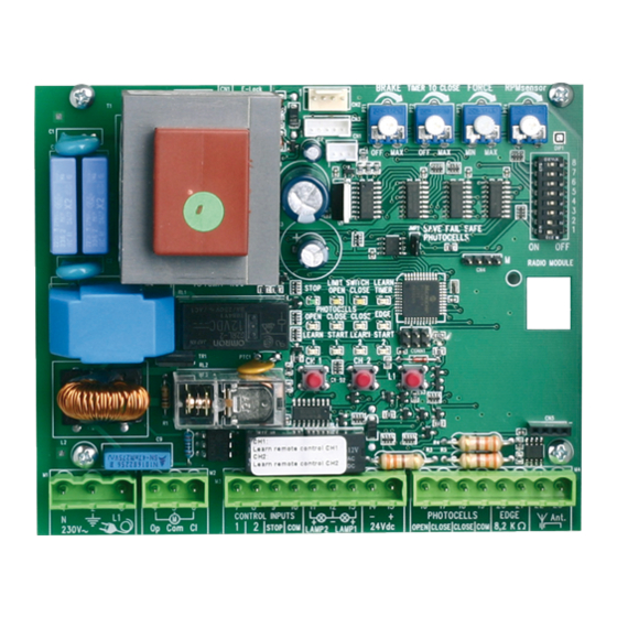
Page 5: Description Of The Leds
CONTROL BOX CONFIGURATION DESCRIPTION OF THE LEDs POINT DESCRIPTION FUNCTION RED LEDs should be switched off. Indication of faults to be rectified; this does not apply to failsafe photocells not connected. (see M1, terminals:1,2,3 Feeder cable “photocell” description) M2, terminals:4,5,6 Drive (Example: short circuit, photocells and/or contact strip) M3, terminals:7,10... - Page 6 PROGRAMS The control board has 5 operating modes (programs). The desired program is set using the dip switch “ON” or “OFF”. DIP 1 Assigned to various drive operating modes. (see separate table) DIP 2 DIP 3 Soft stop (slow run) is active The soft stop is activated 2 seconds before the limit switch is reached.
- Page 7 Separate table for setting the operating modes Impulse transmitter/channel 1 Impulse transmitter/channel 2 DIP3 DIP1 DIP2 Standard 1. impulse opens, the next 1. impulse opens for pedestrians, one stops, the next one gate is moved open for 10 seconds closes, the next one opens (fixed), the next one closes, the next one re-opens for pedestrians Impulse during closing opens...
-
Page 8: Photocells (Optional)
ACCESSORIES PHOTOCELLS (OPTIONAL) The photocells are for safeguarding the gate and must be used. The open/öffnen/ouvrir/open fitting location depends on the gate’s design. EN12453 specifies that a pair of photocells must be installed at a height of 200mm; a second pair must be installed in the same position at a height of 700mm. - Page 9 PUSHBUTTON / KEY-OPERATED SWITCH (OPTIONAL) The control board / drive can be activated using various inputs. This can be done using a hand-held transmitter or key-operated switch (terminals 7+10). Hand-held transmitter = see Teaching the hand-held transmitter Switch input 1 = input control 1. Normal operation Switch input 2 = input control 2.
-
Page 10: Radio Module (Optional)
RADIO MODULE (OPTIONAL) To operate the control board via radio remote control, a radio module must first be installed in slots CN4/CN5. The following modules are available: 801221 (433.92 MHz), 801429 (27.145 MHz), 207542 (315.15 MHz China) TEACHING / DELETING THE HAND-HELD TRANSMITTERS Press button CH1. -
Page 11: Initial Operation/Basic Setting
INITIAL OPERATION/BASIC SETTING Proceed step by step. If you are not sure, start again at the beginning. Take sufficient time to make these settings. 1. Are all components required for operation connected? Motor(s), photocell (!), flashing light, push-button or switch etc? 2. - Page 12 Frequently asked questions How long is the probable service life of a gate opener? When used for private purposes, a correctly installed gate opener can operate perfectly for in excess of 10 years. Both the gate and the gate opener must be checked regularly and serviced in accordance with their respective instructions.
- Page 13 The gate must follow a slope. Not recommended! Change gate! The gate can move in an uncontrolled (dangerous) manner if the gate opener has been released. A stronger force is needed in the upwards direction of the slope and then, in the opposite direction, the gate opener’s force is too strong. The force setting has been altered, but no Disconnect the controller from the power supply for a few seconds in order to activate the difference is apparent.
Need help?
Do you have a question about the LiftMaster Professional CB22 and is the answer not in the manual?
Questions and answers