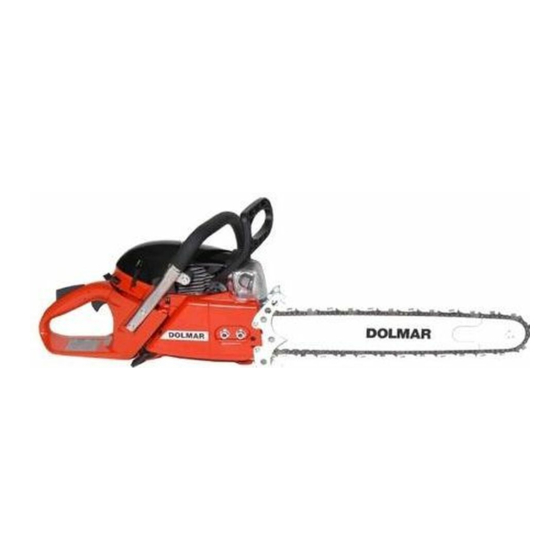
Dolmar PS-6400 Repair Manual
Dolmar chain saw repair manual
Hide thumbs
Also See for PS-6400:
- Owner's and safety manual (76 pages) ,
- Spare parts list (20 pages) ,
- Instruction manual (32 pages)

Related Manuals for Dolmar PS-6400


Summary of Contents for Dolmar PS-6400
- Page 1 Repair Manual PS-6400, PS-6400 H PS-7300, PS-7300 H PS-7900, PS-7900 H www.dolmar.com 02/05 Repair Manual PS-6400/PS-7300/PS-7900...
-
Page 2: Table Of Contents
Vibration damper / Tubular handle ..........32 - 33 Tank ....................34 - 35 Cylinder / Piston ..................36 Outside components / Crankcase / Crankshaft ......37 - 38 Handle Heating ................. 39-41 Torques ....................42 Check operation ..................43 Repair Manual PS-6400/PS-7300/PS-7900... -
Page 3: Technical Data
Fuel tank capacity 0.75 Chain oil tank capacity 0.42 Mixture ratio (fuel/two-stroke oil) - when using DOLMAR oil 50 : 1 - when using other oils 40 : 1 Chain brake engages manually or in case of kickback Chain speed 19.74... -
Page 4: Troubleshooting
No chain lubrication Oil tank/pump No oil on the chain Oil tank empty, oil guide groove dirty, oil-pump adjusting screw incorrectly adjusted, oil pump drive defective Repair Manual PS-6400/PS-7300/PS-7900... -
Page 5: Special Tools
(944.500.891) Torque wrench 3/8” Drive socket (944.500.864) Bit, 152 mm (944.500.865) Bit, 49 mm (944.500.866) Torque wrench 3/8” Drive (950.230.000) Piston stop wedge Wedge for blocking the motor through the exhaust port (944.602.000) Repair Manual PS-6400/PS-7300/PS-7900... - Page 6 (944.500.570) Pressure gauge Pressure guage for checking the carburetor fuel valve (956.004.000) 10 Tachometer Electronic tachometer for measuring the engine speed of 2- and 4-stroke engines (950.233.210) 11 Installation sleeve for radial rings (944.603.410) Repair Manual PS-6400/PS-7300/PS-7900...
-
Page 7: Sprocket Guard / Chain Tensioning System
The chip guide ensures that chips are deflected away from the cut. This is especially important for rip cuts, to prevent clogging. To replace it, push the catch 4 inwards from the outside of the chain guard. Tool Repair Manual PS-6400/PS-7300/PS-7900... -
Page 8: Clutch Drum / Rim Sprocket
Check the clutch drum bearing for damage and wear. Assemble with multipurpose high-performance grease (944.360.000). Check the clutch drum for damage and wear, and replace if worn. Note: Always use a new circlip (927.408.000)! Repair Manual PS-6400/PS-7300/PS-7900... -
Page 9: Chain Brake
CHAIN BRAKE Chain brake The chain brake stops the chain within 0.1 seconds in the event of kickback. The brake band 2 encircles the clutch drum 380°. A spring 1 pulls the brake band around the clutch drum. Repair Manual PS-6400/PS-7300/PS-7900... - Page 10 CHAIN BRAKE Engage the chain brake Push the hand guard forward so that the linkage release the spring tension. Safety note: Strong spring! Never work on the chain brake when the spring is under tension! Repair Manual PS-6400/PS-7300/PS-7900...
- Page 11 Remove the clutch drum 5 (note needle bearing 6) and release the hand guard again slowly. Remove the covering plate 8, assembly with slot head screw 7 (3.5 x 9.5 mm). Remove foam sponge 9. Tool (1,5 Nm ± 0,2) Repair Manual PS-6400/PS-7300/PS-7900...
- Page 12 Check the inside of the brake band for signs of wear. The chain brake is an important safety component. Always check it for wear. A worn brake band must be replaced (927.408.000)! Tool (1,5 Nm ± 0,2) Repair Manual PS-6400/PS-7300/PS-7900...
- Page 13 Before assembly, drive the slotted pin 5 out of the housing with a mandrel (dia. 4 mm) in the direction of the muffler. Install the disengagement mechanism and insert the grooved pin. Important: The circlip 1 must be inserted in the bottom groove. Tool Repair Manual PS-6400/PS-7300/PS-7900...
- Page 14 Push linkage arm 5 up slightly and disengage (it may be necessary to hold the pin against it). Remove hand guard. (4.0 Nm + 0.5) (4,0 Nm + 0,5) Tool (4.0 Nm + 0.5) (4,0 Nm + 0,5) Repair Manual PS-6400/PS-7300/PS-7900...
-
Page 15: Clutch
3200 rpm, clean and inspect the clutch. It may be necessary to replace the springs. Remove the muffler. Block the engine with piston stop wedge (944.602.000). Remove the clutch drum (see page 11). Loosen the clutch 1 with assembly tool (944.500.570) by turning clockwise. Tool Repair Manual PS-6400/PS-7300/PS-7900... - Page 16 Use the assembly wrench (944.500.570) to tighten the clutch. The lug 3 of the clutch drum should not be on the arms of the oil pump drive 2. Replace the muffler gasket 4 (965.531.130). (55,0 Nm ± 2,5) (55.0 Nm ± 2.5) Tool Repair Manual PS-6400/PS-7300/PS-7900...
- Page 17 The oil pump is attached to the crankcase with 2 Torx screws 4 M5 x 12. Removing the clutch drum, see page 11. Removing the clutch, see page 15. (8.0 Nm + 1.0) (8,0 Nm + 1,0) Tool Repair Manual PS-6400/PS-7300/PS-7900...
- Page 18 The oil tank is ventliated by valve 2 in the crankcase. To replace it, drive the valve into the tank with a mandrel (dia. 4 mm) and press in a new valve from the outside with a mandrel (dia. 8 mm). CAUTION: Use mandrel with planar surface! Repair Manual PS-6400/PS-7300/PS-7900...
-
Page 19: Oil Pump
Adjustment range 70° • Right for reduced oil supply • Left for more oil supply Even very small turns of adjusting screw 7 influence the amount of oil supplied to the bar and chain. Repair Manual PS-6400/PS-7300/PS-7900... -
Page 20: Starter
Torx/slotted screws 1 (M5x20). Induction channel (4.0 Nm + 1.0) (4,0 Nm + 1,0) The air duct 2 guides the inducted cool air to the cylinder for proper operation. 4.5 Nm ± 1.0 4,5 Nm ± 1,0 Tool Repair Manual PS-6400/PS-7300/PS-7900... - Page 21 CAUTION: Injury hazard! Secure the starter hand- le when it is pulled out. It will be pulled back very quickly if the cable drum is inadvertently released. Tool (4.5 Nm ± 1.0) (4,5 Nm ± 1,0) Repair Manual PS-6400/PS-7300/PS-7900...
- Page 22 If it does, it can be put back in as shown in the diagram. Before installing the new return spring and the spring cartridge in the fan housing, grease both lightly with multipurpose grease (944.360.000). Repair Manual PS-6400/PS-7300/PS-7900...
-
Page 23: Ignition System
9 from the carburetor and then out of the carburetor base 10. Loose the bowden cable with a needle nose plier. Unscrew screws 11. The carburetor base can now be lifted slightly so that the wires can be pulled through. Tool 10 mm Repair Manual PS-6400/PS-7300/PS-7900... - Page 24 Remove ignition plug. Is ignition plug damaged? has a wrong ignition plug been Replace ignition plug. Use ONLY ignition plugs approved by DOLMAR. See operating used? Are the electrodes sooted? manual! Otherwise the ignition module might get damaged remove the causes for sooted electrodes (bad two-tact oil), wrong mix, defect air filter).
- Page 25 Ground connection with slotted screw 3 (3.5 x 9.5 mm). Always make sure there is a good ground connection! Spark plug NGK BPMR 7 A (965.603.021) BOSCH WSR 6F (965.603.014) Electrode gap 0.5 mm Tool (1.5 Nm ± 0,2) (1,5 Nm ± 0,2) Repair Manual PS-6400/PS-7300/PS-7900...
- Page 26 Set gap to 0.3 mm Place gap gauge (944.500.891) between the flywheel (5,0 Nm - 0,5) (5.0 Nm - 0.5) magnets and the ignition coil. Push the ignition coil against the flywheel and tighten screws 3 (M4 x 20). Tool Repair Manual PS-6400/PS-7300/PS-7900...
- Page 27 Disassamble hand guard (see page 14). The protective hood 4 and carburetor base are fastened to the crankcase with 2 Torx screws 5 (M5 x 20) with loss-proof washers. (6,0 Nm ± 0,5) (6.0 Nm ± 0.5) Tool Repair Manual PS-6400/PS-7300/PS-7900...
- Page 28 As engine speed increases the valves will shut. Periodically check the rubber valves for damages, and replace when necessary. For disassambling press out the rivets. (6.0 Nm ± 0.5) (6,0 Nm 0,5) Tool Repair Manual PS-6400/PS-7300/PS-7900...
- Page 29 Disengage the choke lever (pull out and turn clockwise). Use needle-nose pliers to remove: Plug 1 Bowden cable 4 Fuel hose 6 Impulse hose 5 Unscrew fastening screws 2. Pull carburetor up and out with the manifold. Tool Repair Manual PS-6400/PS-7300/PS-7900...
- Page 30 2 with two 2 screws 3 (M4 x 55) with countersunk square nut 1. During assembly, tighten screws 3 only to 1.0 Nm + 0.5. CAUTION: Don’t forget the bushing 4! (1,0 Nm + 0,5) (1.0 Nm + 0.5) Tool Repair Manual PS-6400/PS-7300/PS-7900...
-
Page 31: Carburetor
USA Version with Limiter Caps Factory setting: L = 1 H = 1 1/8 Idle speed 2500 rpm Max. speed 13500 rpm Electronic speed limiter NOTE: Always use a tachometer when adjusting the carburetor! USA / EPA Repair Manual PS-6400/PS-7300/PS-7900... -
Page 32: Vibration Damper / Tubular Handle
Clamp is fastened to the tubular handle with a Torx screw 2 (6 x 14). Clamp is asymetric, fixing Point of the clamp must face off the cylinder. (5.0 Nm ± 0.5) (5,0 Nm ± 0,5) Tool Repair Manual PS-6400/PS-7300/PS-7900... - Page 33 VIBRATION DAMPER / TUBULAR HANDLE Damping system Vibration damping using the DOLMAR 2-mass system (D2M). Spring 1 tubular handle/cylinder is attached with Torx screw 2 (M6 x 14). Replace forward clutch-side spring 3 (038.114.130) complete with screw and cap. Rear clutch-side spring is fastened with Torx screws (5.0 Nm ±...
- Page 34 To replace the throttle trigger and throttle lockon lever drive out the cylinder pins 4 (3 x 24 mm) and 5 (3 x 38 mm) with a mandrel (ø 2 mm). Tool (4,0 Nm ±0,5) (4.0 Nm ± 0.5) Repair Manual PS-6400/PS-7300/PS-7900...
-
Page 35: Tank
Connect fuel line to carburetor. Insert carburetor adjustment guide. The fuel tank air valve 2 acts only as ventilation. NOTE: Fuel tank air valve 2 is supplied as a complete unit. To replace it, it is necessary to remove the tank. Repair Manual PS-6400/PS-7300/PS-7900... -
Page 36: Cylinder / Piston
The cylinder is screwed to the crankcase with 4 Torx screws 2 (M5 x 20). Assembling the induction hose The induction hose 3 is fixed to the cylinder with a hose clamp 4. Tighten the hose clamp until it has a gap of 3 mm. Tool Repair Manual PS-6400/PS-7300/PS-7900... -
Page 37: Outside Components / Crankcase / Crankshaft
Secure guide bar bolts 5 with “Loctite 243” (980.009.000). Slotted pin 6 for the chain brake mechanism. For disassembly see Page 13. (12,0 Nm ± 0,5) (12.0 Nm ± 0.5) Tool (20.0 Nm ± 1.0) (20,0 Nm ± 1,0) Repair Manual PS-6400/PS-7300/PS-7900... - Page 38 Evenly coat the external ring of the ball bearing 4 with “Loctite 601” and insert into the heated crankcase without pressure. Lubricate the big end bearing 5 with two-stroke oil. Tool (10,0 Nm ± 1,0) (10.0 Nm ± 1.0) Repair Manual PS-6400/PS-7300/PS-7900...
-
Page 39: Handle Heating
Before you replace the contact pins in the housing you need to open the hook 4 a bit using a small knife or similar tool. Repair Manual PS-6400/PS-7300/PS-7900... - Page 40 (ground). No conductivity - make connection to ground and re- place ground line (970.311.570) if needed. Tools Conductivity tester or multi meter to test electrical re- sistance and conductivity. Repair Manual PS-6400/PS-7300/PS-7900...
- Page 41 Measure the resistance between both pin contacts of the tubular handle. Resistance approx. 5 Ohm (at approx. 20°C) Tubular handle (038.310.030) must be replaced if resistance is incorrect. Tools Conductivity tester or multi meter to test electri- cal resistance and conductivity. Repair Manual PS-6400/PS-7300/PS-7900...
-
Page 42: Torques
Induction hose clamp Cross-slot M 3 0.5 – 0.2 Spark clamp attachment ——— 25 +/-5 Cable drum in fan housing Torx 5.5 x 20 4.5 +/-1 Generator armature in crankcase Torx 4 x 20 4 + 1 Repair Manual PS-6400/PS-7300/PS-7900... -
Page 43: Check Operation
CHECK OPERATION Repair Manual PS-6400/PS-7300/PS-7900... - Page 44 DOLMAR GmbH • Postfach 70 04 20 • D-22004 Hamburg • Germany Form-Nr.: 995 724 020 Repair Manual PS-6400/PS-7300/PS-7900...
Need help?
Do you have a question about the PS-6400 and is the answer not in the manual?
Questions and answers