Advertisement
Quick Links
Download this manual
See also:
User Manual
I C - I AND IC-I F
GENERAL DESCRIPTION
The IC-1 and IC-1 F are single-channel, single-
line intercom stations designed for use with
dynamic headsets.
The IC-1 is a compact, lightweight unit which
may be worn on the user's belt, or mounted
permanently to other equipment. Parallel-wired
male and female XLR-3 connectors, mounted on
the rear panel, allow units to be daisy-chained
using prefabricated intercom cables.
The IC-1 F is a flush-mount version of the IC-1
designed for permanent installation in an
electrical pull box. The unit is connected to the
intercom system by means of combination wire-
wrap, screw clamp terminals.
Both the IC-1 and IC-1 F are available with and
without light signalling capability. The light
signal versions are distinguished by the presence
of a Call Indicator Light on the front panel. For
purposes of documentation, the light signal
versions will be designated the IC-1/LS (an IC-1
with light signalling, and the IC-1 F/LS (an IC-1 F
with light signalling).
SPECIFICATIONS
Specifications apply to all versions unless
otherwise noted.
Frequency Response:
Transmit: 150-7,000 Hz t 1 , -3 dB.
Receive: 180-6,000 Hz
+1,
-3 dB.
Equivalent lnput Noise:
Mic Input: 2 microvolts (-1 16 dBV)
150-7,000 HZ.
Input Level:
Mic: 5 millivolts nominal, 12 millivolts
maximum.
Line: 1 volt (0 dBM) nominal, 4 volts (12 dBM)
maximum.
lnput Impedance:
Mic: Greater than 5,000 ohms. (Unit is
designed for use with 50-600 ohm phones).
Line: Greater than 10,000 ohms.
Output Impedance:
Phones: 60 ohms (Unit is designed for
use with 150-600 ohm phones.)
Output Power:
Phones: 75 milliwatts into 150 ohms.
Line: 10 milliwatts (+I0 dBM).
Total Harmonic Distortion:
Transmit: 1% at 10 dBM.
Receive: 1% at 75 milliwatts.
Common Mode Rejection:
Line: 40 dB at 60 Hz.
Power Requirements:
Voltage: 24 Vdc nominal. Unit will
operate on 12-30 Vdc.
Current: No signal
-
8 milliamps (IC-1, IC-IF),
12 milliamps (IC-1/LS, IC-1 F/LS).
Average talk
-
12 milliamps (IC-1, IC-IF),
20 milliamps (IC-1/LS, IC-1 F/LS).
Signalling
-
30 milliamps (IC-I/LS, IC-1 F/LS).
Dimensions (without external connectors):
IC-1, IC-I/LS: 1.75 inches (44.45 mm) high x
3.0 inches (76.2 mm) wide x 5.39 inches
(136.9 mm) long.
IC-IF, IC-1F/LS: 4.5 inches (114.3 mm) high x
4.62 inches (117.35 mm) wide x 2.5 inches
(63.5 mm) deep behind front panel. If unit is
installed using screw-clamp terminals, wire-
wrap pins may be cut off and depth reduces t o
2.15 inches (54.61 mm).
Weight:
IC-1, IC-1/LS: 1.5 Ibs (0.51 kg)
Connectors:
IC-1/LS: One XLR-4M for headset
connection. One XLR-3M and one XLR-3F,
wired in
parallel, for intercom line
connection.
IC-1 F, IC-1 F/LS: One XLR-4M for headset
connection. Three combination screw-clamp,
wire-wrap terminals for intercom line
connection. Screw-clamp terminals accept
No. 22 through No. 14 AWG stranded or solid
wire.
Advertisement

Subscribe to Our Youtube Channel
Related Manuals for Telex IC-1


Summary of Contents for Telex IC-1
- Page 1 XLR-3 connectors, mounted on the rear panel, allow units to be daisy-chained using prefabricated intercom cables. The IC-1 F is a flush-mount version of the IC-1 designed for permanent installation in an electrical pull box. The unit is connected to the intercom system by means of combination wire- wrap, screw clamp terminals.
-
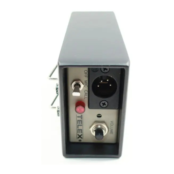
Page 2: Installation
Headphone VOLUME Control: Adjusts headphone listen level. Does not affect mic level. MICION Switch (IC-1, IC-IF): In the MIC position, the microphone is shut off but the intercom line is still monitored by the phones. In the ON position, the microphone is operational for two-way communication. - Page 3 HEADSET CONNECTOR MIC ON/OFFAND CALL SWITCH MICROPHONE ON/OFF SWITCH HEADPHONE VOLUME CONTROL CONTROL IC-1FILS FRONT PANEL IC-IF FRONT PANEL - . - - - IC-IF Reference Guide...
-
Page 4: Maintenance
MAINTENANCE IC-1, IC-IILS Mechanical Exploded View... - Page 5 ITEM NO. Bezel Nut, Hex No. 3/8-32 Lens, LED 4* * Clip, Lens Mtg. Screw No. 4-40 x Connector, XLR-4M (J2) PCB Assembly, Audio Screw, No. 4-40 Connector, 14-Position (J1) Pin, Snap In (Not Shown) Connector (J5) 11** Pin, Snap In (Not Shown) PCB Assembly, 20 kHz Light Signal 12** Screw, No.
- Page 6 IC-1 F, IC-1 FILS Mechanical Exploded View...
- Page 7 ITEM NO. 5* * 14** 26** 92863, Rev AB IC-IF, IC-1FILS Mechanical Parts List DESCRIPTION Nut, Hex, No. 3/8-32 Collet Knob, Control Lens, LED Screw, No. 4-40 x Connector, XLR-4M (J2) Bezel Screw, No. 6-32 x Cover Plate, Front Bracket Washer, Lock, Int.
- Page 8 92846. Rev I C - I Audio PCB Assembly Component Layout IC-IILS, IC-IFILS 20 KHz Light Signal PCB Assembly Component Layout 96079. Rev H...
- Page 9 I C - I Audio PCB Assembly Parts List All resistors in ohms, 1/4 watt, +5% unless otherwise noted. All capacitors are in microfarads unless otherwise noted. REFERENCE NO. Capacitor, 1, 35V, Tantalum Capacitor, 0.01, 1 O O V C2,21 C5,11 Capacitor, 10, 25V Electrolytic C6,9,12...
- Page 10 IC-I/LS, IC-IF/LS 20 KHz Light Signal PCB Assembly Parts List All resistors in ohms, All capacitors are in microfarads unless otherwise noted. REFERENCE NO. C1,2,3 C5,7,9 Q1,3 R2,5 R3,15 W, +5% unless otherwise noted. DESCRIPTION Capacitor, Ceramic, 0.001, 50V, Capacitor, Ceramic, 100 pF, 500V, Capacitor, Tantalum, 0.1, 35V, f20°/o Capacitor NPO, Ceramic, 0.0022, 50V, k2% Capacitor, Electrolytic, 4.7, 25V, +20°/0...
- Page 11 MICROPHONE PRE-AMPLIFIER NOTES: 1. ALL RESISTORS IN OHMS, 1/4 WATT, +5% UNLESS OTHERWISE NOTED. 2. ALL CAPACITORS IN MICROFARADS UNLESS OTHERWISE NOTED. ALL VOLTAGES ARE D C MEASURED USING A HIGH IMPEDANCE METER UNDER NO-SIGNAL CONDITIONS WlTH CHASSIS AS REFERENCE. 4.
- Page 12 NOTES: 1. ALL RESISTORS IN OHMS, % WATT, f 5 % UNLESS OTHERWISE NOTED. 2. ALL CAPACITORS IN MICROFARADS UNLESS OTHERWISE NOTED. 3. ALL VOLTAGES ARE DC MEASURED USING A HIGH IMPEDANCE METER WlTH CHASSIS AS REFERENCE. 4. WHERE TWO VOLTAGES ARE INDICATED, THE UPPER SIGNAL AT P5-4 AND THE LOWER IS WlTH 20 KHz AT 100 MV (CALL SIGNAL IN) AT P5-4.
Need help?
Do you have a question about the IC-1 and is the answer not in the manual?
Questions and answers