
Related Manuals for Thermaltake VG6000BNS


Summary of Contents for Thermaltake VG6000BNS
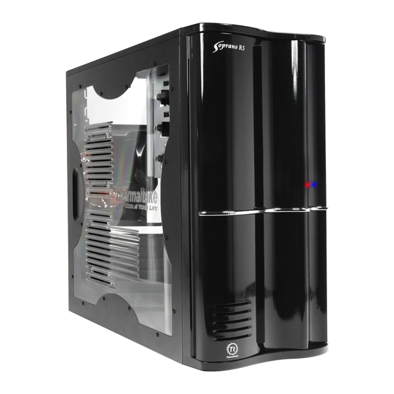
- Page 1 All other registered trademarks belong to their respective companies. 2007 Thermaltake Technology Co.,Ltd. All Rights Reserved. www.thermaltake.com...
- Page 2 User's Manual VG6000 Series...
-
Page 3: Table Of Contents
Contents Contents Chapter 1. Product Introduction 1.1 Specification Chapter 2 Case Mechanical Operation 2.1 How to open the side panel 2.2 How to install PSU 2.3 5.25" device installation 2.4 HDD installation 2.5 3.5" device installation 2.6 Motherboard installation 2.7 PCI slot usage 2.8 Front fan installation (optional) Chapter3 Motherboard &... -
Page 4: Chapter1. Product Introduction
Chapter1. Product Introduction Chapter1. Product Introduction 1.1 Specification Model Model VG6000BNS VG6000BNS VG6000BWS VG6000BWS Case Type Case Type Full Tower Full Tower Honeycomb see - Transparent window Side Panel Side Panel Transparent window through window Dimension Dimension 540.0 x 205.0 x 496.0 mm 540.0 x 205.0 x 496.0 mm... -
Page 5: Chapter 2 Case Mechanical Operation
Chapter 2 Case Mechanical Operation Chapter 2 Case Mechanical Operation 2.1 How to open the side panel Transparent side panel To remove the side panel, please remove upper and bottom thumb screws on the back of the case. Push the handle then swing out the side panel. Honeycomb see-through side panel To remove the side panel, Insert the provided key and... -
Page 6: How To Install Psu
Push the handle then swing out the side panel. 2.2 How to install PSU Secure it by screws as shown. Place power supply unit in the right position. 2.3 5.25" device installation Open the front door first. Remove the 5.25" drive bay plastic cover by pressing it at the bottom corner . - Page 7 Remove the 5.25" drive bay metal cover. Find the drive bay rails right behind the plastic drive bay cover. Mount drive rails to 5.25" device and fasten the device using screws. Slide the 5.25" device into 5.25" device installation drive bay till the fix-position. complete.
-
Page 8: Hdd Installation
2.4 HDD installation Press the clip on each side of Place HDD on the drive tray, the HDD tray and pull backward then secure HDD by screws. to take off the HDD tray. HDD installation complete. Slide HDD tray into the cage till the fix-position. - Page 9 Place and fasten 3.5" device by screws. 3.5" device installation Slide the 3.5" tray into drive complete. bay till the fix-position.
-
Page 10: Motherboard Installation
2.6 Motherboard installation Remove thumb screws on the motherboard tray. Slide the motherboard tray Place the motherboard tray on a flat surface and mount the motherboard. toward the drives and remove it. Screw up the thumb screws. Place the motherboard tray back to the case and slide it Note: back to the position. -
Page 11: Pci Slot Usage
2.7 PCI slot usage Take off the tool-free kit as Remove the PCI bracket. shown. Locate Graphic Card to the Put back the tool-free kit to motherboard through fixing it lock the Graphic Card as on the space of PCI bracket. shown. -
Page 12: Front Fan Installation (Optional)
2.8 Front fan installation (optional) Remove both side panels. Remove the front panel using a flat-head screwdriver. Take off the whole front panel. - Page 13 Find the fan filter from the enclosed Place the 120mm fan and package and place it on the fan. Front fan fasten the fan by screws. installation complete.
-
Page 14: Chapter3 Motherboard & Leads Installation
Chapter3 Motherboard & Leads Installation Chapter3 Motherboard & Leads Installation 3.1 Motherboard Installation Each motherboard has different standoff layout. It is highly suggested that you refer to your motherboard's manual when installing motherboard into the Case. The cases are applicable with Standard ATX, Micro ATX motherboards. -
Page 15: Case Led Connection
3.2 Case LED connection On the front of the case, you can find some LEDs and switch leads (POWER SW*1, POWER LED*1, H.D.D. LED*1, RESET SW*1). Please consult user manual of your motherboard manufacturer, then connect these leads to the panel header on the motherboard. These leads are usually labeled;... -
Page 16: Esata Connection
3.4 eSATA connection Connect this to your motherboard at SATA. 3.5 Audio Connection - Please refer to the following illustration of Audio connector and your motherboard user manual. - Please select the motherboard which used AC'97 or HD Audio (Azalia), (be aware of that your audio supports AC'97 or HD Audio (Azalia)) or it will damage your device(s). -
Page 17: Chapter4 Rsi Cooler And Power Supply
Chapter4 RSI Cooler and Power Supply Chapter4 RSI Cooler and Power Supply 4.1 RSI Cooler (Optional) P/N : CL-P0441 Designed for Intel Core 2 Duo Processor Application for Intel Core 2 Duo / Pentium D / Celeron series (Socket LGA775) FEATURES: - Aluminum Crotch Fin provides more heat dissipation area. -
Page 18: Rsi Power Supply (Optional)
4.2 RSI Power Supply (Optional) Express 12V 2.0 Litepower 400W AMD/ Universal S-ATA Intel 24(20) Dual Core Support P/N: W0161 W/PFC P/N: W0162 No PFC FEATURES: - Intel ATX 12V 2.0 Compatible. - Supports 6-pin PCI-Express, 2 SATA, and 20+4 pin connector. - Dual +12V output circuit provides steady output for system.
Need help?
Do you have a question about the VG6000BNS and is the answer not in the manual?
Questions and answers