
Subscribe to Our Youtube Channel
Related Manuals for Thermaltake VD6000BNS


Summary of Contents for Thermaltake VD6000BNS
-
Page 1: User Manual
VD6000 SERIES User Manual C 2006 Thermaltake Technology Co.,Ltd. All Rights Reserved. -
Page 2: Table Of Contents
Contents Chapter l Product Introduction 1.1 Specification Chapter 2 Case Mechanical Operation 2.1 How to open the side panel 2.2 Front fan Installation (Optional) 2.3 Installing 5.25" device 2.4 PCI slot tool-free function operation 2.5 Installing 3.5" HDD 2.6 Installing 3.5" device Chapter 3 Motherboard &... -
Page 3: Chapter L Product Introduction
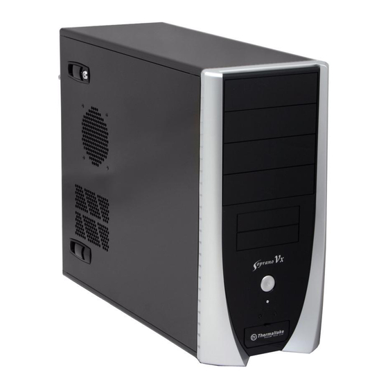
Chapter l Product Introduction 1.1 Specification VD6000BNS >>> Model Model VD6000BNS Case Type Case Type Middle Tower Middle Tower Net Weight Net Weight 6.15 kg Dimension Dimension 410 x 190 x 510 mm (H*W*D) (H*W*D) Front (Intake) : 120 x 120 x 25 mm (optional) -
Page 4: Chapter2 Case Mechanical Operation
Chapter2 Case Mechanical Operation 2.1 How to open the side panel 2.2 Front Fan Installation (Optional) Œ Remove the front panel first. u To remove the side Make sure the side Please find the side panel lock is opened. panel, please remove panel key in the back •... -
Page 5: Installing 5.25" Device
2.3 Installing 5.25" Device Œ Remove the front panel. • Remove the 5.25" drive ‘ Place 5.25" device into bay metal cover. the drive bay. •Unscrew the 5.25" Ž Remove the 5.25" drive bay cover. drive bay cover. ’ Put back the lock device and turn lock device clockwise to lock. •... -
Page 6: Pci Slot Tool-Free Function Operation
2.5 Installing 3.5" HDD 2.4 PCI slot tool-free function operation u Turn lock device counter-clockwise to unlock. v Remove lock device. w Place HDD into the drive bay. ΠOpen the plastic clip then take off the PCI bracket. Put back the lock device and turn lock device clockwise to secure the HDD. -
Page 7: Installing 3.5" Device
2.6 Installing 3.5" device • Remove the 3.5" drive Œ Remove the front panel. • Insert lock device and turn clockwise to secure the drive. bay cover . 3.5" device installation complete. Ž Turn lock device counter-clockwise to unlock. • Remove lock device and insert drive from the front of the chassis. -
Page 8: Chapter3 Motherboard & Leads Installation
Chapter3 Motherboard & Leads Installation 3.1 Motherboard Installation 3.2 Case LED connections On the front of the case, you can find some LEDs and switch Each motherboard has different standoff layout. It is highly leads (POWER SW*1, POWER LED*1, H.D.D. LED*1, suggested that you refer to your motherboard's manual when RESET SW*1, SPEAKER*1). -
Page 9: Usb2.0 & Ieee1394 Firewire Connection
3.3 USB2.0 & IEEE1394 Firewire connection 3.4 Audio connections USB connection Please consult your motherboard manual to find out the section of "USB connection". Please refer to the following illustration of Audio connector and your motherboard user manual. VCC 1 VCC 2 Please select the motherboard which used AC'97 or HD Audio (Azalia), (be aware of that your audio supports AC'97 or HD Audio (Azalia)) or... - Page 10 AC Input cycled on/off under high temperature condition. Furthermore, it has been approved by UL, CSA, TUV, VDE, NODIC, CB, FCC, CE, CNS. There are three main products of Thermaltake PSU, it is divided into standard, VR and specialty power supply unit. Please refer to http://www.thermaltake.com/purepower/main.htm...
Need help?
Do you have a question about the VD6000BNS and is the answer not in the manual?
Questions and answers