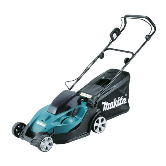
Makita BLM430 Technical Information
430mm cordless lawn mower
Hide thumbs
Also See for BLM430:
- Instruction manual (101 pages) ,
- Instruction manual (97 pages) ,
- Instruction manual (18 pages)
Advertisement
Quick Links
Download this manual
See also:
Instruction Manual
T
ECHNICAL INFORMATION
Model No.
Description
C
ONCEPT AND MAIN APPLICATIONS
Models LM430D, BLM430, (HML01)*
with rotary blade cutting system.
Its main benefits are:
• Environment-friendly with zero emission and minimum noise pollution
• Compatible with both Makita 36V-2.6Ah Li-ion battery BL3626
and 36V-2.2Ah Li-ion battery BL3622A
• Compatible with Battery converters, BCV01 and BCV02
• Adjustable 13 cutting heights from 20mm to 75mm
• The storage space can be saved by standing the machine on its rear
end (See illustrated right.)
• Handle height is adjustable in 2 stages
This product is available in the variations listed below.
Model No.
Charger
LM430DZ
LM430DWB
DC36WA
LM430DWBE
DC36WA
BLM430Z
BLM430RD
DC36RA
BLM430RDE
DC36RA
BLM430ZX2C
HML01Z*
1
HML01C1*
DC36WA
1
Note: All models also include the accessories listed below of "Standard equipment".
S
pecification
Cell
Voltage: V
Battery
Capacity: Ah
Charging time (approx.): min.
Max output (W)
No load speed: min.
Type
Blade
Inner diameter: mm (")
Cutting width: mm (")
Cutting height adjustment range: mm (")
Electric brake
Soft start
Weight according to
EPTA-Procedure 01/2003*
*2: No load speed of the cutting tool
*3: with battery, blade, grass bag
*4: for North and Central American countries
*5: All countries except North and Central American countries
BLM430, LM430D
430mm Cordless Lawn Mower
is Cordless Lawn mower equipped
1
Battery
Type
Quantity
No
No
No
BL3622A
1
BL3622A
2
No
No
No
BL3626
1
BL3626
2
No
No
No
No
No
No
BL3622A
1
¹=rpm*
ˉ
2
Rotary type 2 tooth blade
20 - 75 (13/16 - 2-15/16),
: kg (lbs)
3
Battery
Battery
cover
converter
No
No
No
No
1
No
No
No
No
No
1
No
No
BCV02
No
No
No
No
Li-ion
36V
2.2/ 2.6
60 with DC36WA/
22 with DC36RA
580
3,600
24.0 (15/16)
430 (17)
13 stages
Yes
Yes
18.1 (39.9)*
,
4
17.9 (39.4)*
5
W
Dimensions: mm (inch)
minimum
Length (L)
maximum
Width (W)
minimum
Height (H)
maximum
490~500
(19-1/4~19-3/4)
S
tandard equipment
Socket wrench ........................................ 1
Blade 430 .............................................. 1
Note: The standard equipment for the tool
shown above may vary by country.
O
ptional accessories
Battery 3622A
Battery BL3626
Charger DC36WA
Fast charger DC36RA
Battery converter BCV01
Battery converter BCV02
PRODUCT
P 1/ 8
H
L
1,450 (57)
1,490 (58-3/4)
460 (18-1/8)
950 (37-1/2)
1,020 (40-1/4)
810 (32)
(without Rear bag)
460 (18-1/8)
Advertisement

Related Manuals for Makita BLM430


Summary of Contents for Makita BLM430
- Page 1 Cordless Lawn mower equipped with rotary blade cutting system. Its main benefits are: • Environment-friendly with zero emission and minimum noise pollution • Compatible with both Makita 36V-2.6Ah Li-ion battery BL3626 Dimensions: mm (inch) and 36V-2.2Ah Li-ion battery BL3622A minimum...
- Page 2 P 2/ 8 epair CAUTION: Repair the machine in accordance with “Instruction manual” or “Safety instructions”. [1] NECESSARY REPAIRING TOOLS Code No. Description Use for 1R285 Round bar for Arbor 11-50 removing Plane bearing 10 from Front/ Rear wheels [2] ASSEMBLY/ DISASSEMBLY [2]-1.
- Page 3 P 3/ 8 epair [2] ASSEMBLY/ DISASSEMBLY [2]-1. Handle section (cont.) ASSEMBLING Assemble Handle section in the reverse order of disassembly. Note: • Face the top of Lever to the upper side when assembling Lever to Switch lever. (Fig. 7) While holding the insert nut on lever so as not to separate, assemble Lever to Switch lever with M4x20 Pan head screw with WR.
- Page 4 P 4/ 8 epair [2] ASSEMBLY/ DISASSEMBLY [2]-2. Motor section REPLACING (1) Remove Blade. (2) Pull Lock lever to release the locking of Battery cover complete, and then open Battery cover complete. (Fig. 11) Remove the hinge of one side carefully, and separate it from Cowling. (Fig. 12) And then, remove the other hinge in the same way.
- Page 5 P 5/ 8 epair [2] ASSEMBLY/ DISASSEMBLY [2]-3. Change lever section DISASSEMBLING (1) Remove Cowling. (Refer to the previous page.) (2) Shift Change lever to the position of grass cutting height 75mm. (3) Detach the hook of Tension spring 16 from the projection of Deck using long-nose pliers. (Fig. 17) (4) Put a wood under Deck to raise Wheels from the ground.
- Page 6 P 6/ 8 epair [2] ASSEMBLY/ DISASSEMBLY [2]-4. Wheels DISASSEMBLING (1) Pull Front wheel caps straight out of Front wheels. (Fig. 22) Remove Rear wheel caps in the same way. (2) Remove M8 Collared hex nuts and Front wheels from Front shaft. (Fig. 23) Separate Rear wheels from Rear shaft in the same way.
-
Page 7: Circuit Diagram
P 7/ 8 epair Fig. 30 [2] ASSEMBLY/ DISASSEMBLY [2]-5. Connecting rod, Shafts (cont.) Rear shaft ASSEMBLING Front shaft Assemble each wheel section in the reverse order of disassembly. Distinguish Front shaft from Rear shaft by the white paint. (Fig. 30) white paint ircuit diagram Fig. - Page 8 P 8/ 8 iring diagram (cont.) Fig. D-3 To Switch Terminal Fix Lead wires (black, white) in these Lead wire holders. Connect Flag receptacles as drawn above. Be careful to the directions. Lead unit Controller Fix Lead wires (red, blue) in these Lead wire holders.
Need help?
Do you have a question about the BLM430 and is the answer not in the manual?
Questions and answers