Table of Contents
Advertisement
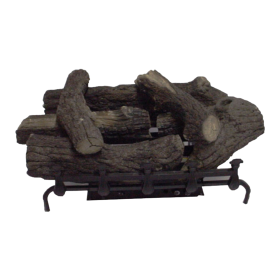
Unvented Gas Log Heater
or Vented Decorative
Appliance
Models:
PH18
(for use with PH18-R Log Sets),
PH24
(for use with PH24-R or PH30-R Log Sets)
WARNINGS
If the information in this manual is not
followed exactly, a fire or explosion may
result causing property damage, personal
injury or loss of life.
– Do not store or use gasoline or other
flammable vapors and liquids in the
vicinity of this or any other appliance.
– WHAT TO DO IF YOU SMELL GAS
• Do not try to light any appliance.
• Do not touch any electrical switch; do
not use any phone in your building.
• Immediately call your gas supplier
from a neighbor's phone. Follow the
gas supplier's instructions.
• If you cannot reach your gas supplier,
call the fire department.
– Installation and service must be
performed by a qualified installer,
service agency or the gas supplier.
Installation and Operating
652035
Instructions
PH logs cover
This is an unvented gas-fired heater. It uses air
(oxygen) from the room in which it is installed.
Provisions for adequate combustion and ventilation
air must be provided. Refer to Page 6.
INSTALLER: Leave this manual with the appli-
ance.
CONSUMER: Retain this manual for future
reference.
65D2035 12/11 Rev. 6
Advertisement
Table of Contents

Related Manuals for MHSC PH18


Summary of Contents for MHSC PH18
- Page 1 Unvented Gas Log Heater or Vented Decorative Appliance Models: PH18 (for use with PH18-R Log Sets), PH24 (for use with PH24-R or PH30-R Log Sets) WARNINGS Installation and Operating 652035 Instructions If the information in this manual is not PH logs cover...
-
Page 2: Table Of Contents
CONTENTS PH Gas Logs Thank you and congratulations on your purchase of an MHSC Log Set. PLEASE READ THE INSTALLATION AND OPERATION INSTRUCTIONS BEFORE USING THE APPLIANCE! IMPORTANT: Read all instructions and warnings carefully before starting installation. Failure to follow these instructions may result in a possible fire hazard and will void the warranty. -
Page 3: Important Safety Information
IMPORTANT SAFETY INFORMATION PH Gas Logs OWNER INSTALLER Please retain these instructions for future reference. Please leave these instructions with the appliance. • Any change to this heater or its controls can be dangerous. • Improper installation or use of the heater can cause serious injury or death from fire, burns, explosion or carbon monoxide poisoning. -
Page 4: Codes
IMPORTANT SAFETY INFORMATION PH Gas Logs as they are burned off during the initial operation of the appliance; possibly causing headaches or eye or lung Never connect unit to private (non-utility) irritation. This is a normal and temporary occurrence. gas wells. This gas is commonly known The initial break-in operation should last two to three as wellhead gas. -
Page 5: Product Features
PRODUCT FEATURES PH Gas Logs GAS SPECIFICATIONS IGNITION CONTROLS Min.Input Max. Input Model Fuel Control BTU/h BTU/h Piezo ignitor allows ignition of the pilot without the PH18NM Nat. Manual 18,000 30,000 use of matches or batteries. PH18NV Nat. Millivolt 26,000 30,000 Manual control has three (3) positions: PH24NM... -
Page 6: Getting Started
GETTING STARTED PH Gas Logs Carefully inspect the contents for shipping damage. If any • Handle the gas log burner assembly by parts are missing or damaged, immediately inform the the burner only. Do not pick the unit up dealer from whom you purchased the appliance. Do not by the burners or grate (not attached to attempt to install any part of the appliance unless you frame). -
Page 7: Fireplace And Hearth Dimensions
FP2530 to the rear wall of the fireplace Glass door frames Model with adjustable PH18 25” 13” 17Z\x” 17” louvers should (635 mm) (330 mm) (445 mm) (432 mm) FP2530 have the louvers... -
Page 8: Clearances And Height Requirements
Heat Resistant Material Requirements with No Figure 3 - Sidewall and Ceiling Clearances Mantel or Combustible Projection Heat Resistant Material PH18/24 Requirements Heat resistant material (minimum requirements) Measurement for Safe Installation FP1996 with no wooden mantel or other combustible 12"... -
Page 9: Installation Requirements
INSTALLATION REQUIREMENTS PH Gas Logs 12" 10" 8" 8" or More of Heat 6" Resistant Material Heat 2 " Resistant Hood Material 8" 14 " 18 " 22 " 26" Heater in Fireplace or Hood Figrebox Heater in Fireplace or FP2923 Firebox Figure 5 -... -
Page 10: Floor Clearance
FLOOR CLEARANCE PH Gas Logs The gas log heater must be installed at least 5" above any combustible flooring material, such as carpeting or tile, which is closer than 14" to the base of the fireplace. The minimum distance must be maintained from the top surface of carpeting, tile, etc. Figure 8 The gas log heater may be installed nearer to the floor if a minimum of 14"... -
Page 11: Installation
INSTALLATION PH Gas Logs DAMPER STOP INSTALLATION: BEFORE FULLY INSTALLING THE UNIT: A damper stop must be provided with the unit. Contact your • Turn OFF the gas supply to the fireplace or fire- dealer to obtain one. The damper stop must be installed as box. -
Page 12: Assembly Procedure
INSTALLATION PH Gas Logs CONNECT THE GAS LINE ASSEMBLY PROCEDURE NOTICE: A qualified gas appliance installer must 1. Center the gas log unit in the fireplace or firebox. connect the heater to the gas supply. Consult all local 2. Install Grate: Insert longest middle grate bar in one of codes. -
Page 13: Check Gas Pressure
INSTALLATION PH Gas Logs CHECk GAS PRESSURE MILLIVOLT CONTROL The heater gas inlet connection is a 3/8" NPT at the valve. Figure 14 All units have the inlet connection on the right side, when The valve regulator controls the burner pressure which you face the unit. -
Page 14: Electrical Wiring - Millivolt
ELECTRICAL WIRING - MILLIVOLT PH Gas Logs Label all wires prior to disconnection when servicing controls. Wiring errors can cause improper and dangerous operation. Verify proper operation after servicing. ODS Pilot On/Off Switch ODS Pilot Wall Switch Millivolt Valve On/Off Switch Spade Terminal TH = 3 TP = 1... -
Page 15: Optional Remote Receiver
ELECTRICAL WIRING - MILLIVOLT PH Gas Logs CONNECT OPTIONAL REMOTE RECEIVER Follow instructions supplied with the remote. Connect the wires to the two .25" male connectors located on the left side of the valve when facing the unit (Refer to Page 17, Figure 15). Do not let wire touch grate or burner. -
Page 16: Log Placement
This may cause sooting. LG1084 Only place volcanic PH18 rear log 1 rock on the floor of the fireplace. During initial operation o f t h e n e w h e a t e r,... - Page 17 5. Rest Left Top Log (#5) on front LG1086 and rear log cutouts. Figure 19 PH18 log 4 6. Rest Right Top Log (#6) on front and rear log cutouts. Figure 19 Figure 19 LG1087 LG1087 65D2035 PH18 logs 5 6...
-
Page 18: Ph24-R
LOG PLACEMENT PH Gas Logs The positioning of the logs are critical to the safe and clean operation of this heater. Sooting and other problems may result if the logs are not properly and firmly positioned in the appliance. Never add additional logs or embellishments such as pine cones, vermiculite or rock wool to the heater. - Page 19 LOG PLACEMENT PH Gas Logs 4. P l a c e F r o n t L o g ( # 4 ) i n between burner and grate so that notched areas fit between grate supports. Figure 22 Figure 22 LG1090 Front Log #4 Left Top Log #5...
-
Page 20: Ph30-R
LOG PLACEMENT PH Gas Logs The positioning of the logs are critical to the safe and clean operation of this heater. Sooting and other problems may result if the logs are not properly and firmly positioned in the appliance. Never add additional logs or embellishments such as pine cones, vermiculite or rock wool to the heater. - Page 21 LOG PLACEMENT PH Gas Logs 4. Place Front Log (#4) in between burner and grate so that notched areas fit between grate supports. Figure 26 LG1094 Figure 26 Front Log #4 Right Top Left Top Log #5 Log #6 LG1094 PH30 log 4 5.
-
Page 22: Flame Appearance
FLAME APPEARANCE PH Gas Logs Flames from the pilot, front and rear burner should be visually checked as soon as the heater is installed. In addition, periodically check the flames visually during operation. CHECk THE PILOT FLAME The pilot flame must always be present when the heater is in operation. It should just touch the top of the thermocouple tip for natural. -
Page 23: Burner Flame
FLAME APPEARANCE PH Gas Logs In normal operation at full rate after 15 minutes, the following flame appearances should be observed: LG1099 Figure 32 - Correct Burner Flame Appearance The left and right flames should be yellow and extend 1" to 2"... -
Page 24: Operating Instructions
CHECkING THE BURNER FLAME PH Gas Logs OPERATING INSTRUCTIONS Avoid any drafts that alter burner flame patterns. Do not allow fans to blow directly into the fireplace. Do not place a blower inside the burn area of the firebox. Ceiling fans may create drafts that alter flame patterns. -
Page 25: For Your Safety Read Before Lighting
OPERATING INSTRUCTIONS PH Gas Logs FOR YOUR SAFETY, READ BEFORE LIGHTING If you do not follow these instruction exactly, a fire or explosion may result causing property damage, personal injury or loss of life. A. This appliance is equipped with an ignition device which automatically lights the pilot. Do not try to light the unit by hand. -
Page 26: Manual Control Lighting Instructions
OPERATING INSTRUCTIONS PH Gas Logs MANUAL CONTROL LIGHTING INSTRUCTIONS 1. STOP! Read the safety information. 2. Make sure the manual shutoff valve is fully open. 3. This heater is equipped with an ignition device (piezo) which automatically lights the pilot. Rotate 4. -
Page 27: Millivolt Control Lighting Instructions
OPERATING INSTRUCTIONS PH Gas Logs MILLIVOLT CONTROL LIGHTING INSTRUCTIONS 1. STOP! Read the safety information label. 2. Make sure the manual shutoff valve is fully open. 3. This gas log set is equipped with an ignition device (piezo) which automatically lights the pilot. If piezo ignitor does not light the pilot, refer to instructions for Match Lighting Instructions, Page 28. -
Page 28: Match Lighting Instructions
OPERATING INSTRUCTIONS and CLEANING & SERVICING PH Gas Logs MATCH LIGHTING INSTRUCTIONS 1. Remove any items necessary for easy access to the pilot (for example: logs, screens, etc.). 2. Follow appropriate lighting instructions found previously. Instead of pushing and releasing the piezo button, light a match and hold the flame to the end of the pilot and ignite the pilot. -
Page 29: Troubleshooting
TROUBLESHOOTING PH Gas Logs Turn off appliance and allow to cool before NOTE: All troubleshooting items are listed in order of operation. cleaning. Only a qualified service person should service and repair the heater. Problem Possible Cause Solution When ignitor button is 1. - Page 30 TROUBLESHOOTING PH Gas Logs Problem Possible Cause Solution 1. Press in control knob fully. ODS/pilot lights, but flame 1. Control knob not fully pressed in. goes out when control 2. After ODS/pilot lights, keep control knob 2. Control knob not pressed in long knob is released.
-
Page 31: Replacement Parts
REPLACEMENT PARTS PH Gas Logs 7 - Millivolt 7 - Manual 652035 PH parts Failure to position the parts in accordance with these diagrams or failure to use only parts specifically approved with this appliance may result in property damage or personal injury. -
Page 32: Illustrated Parts Breakdown
REPLACEMENT PARTS PH Gas Logs Ref. Description Qty. PH18NM/NV PH18PM/PV PH24/30NM/NV PH24/30PM/PV Burner 65D1053 65D1054 65D1055 65D1056 Piezo Ignitor 14D0503 14D0503 14D0503 14D0503 Piezo Wire 00K0632 00K0632 00K0632 00K0632 Pilot Tube (not shown) 49D0050 49D0050 49D0050 49D0050 Manual Control Injector 56D0613 20H3144 20H3152... -
Page 33: Logs
REPLACEMENT PARTS PH Gas Logs PH24-R PH18-R PH30-R Ref. Description Qty. PH18-R PH24-R PH30-R Rear Log #1 20303849 20303855 65D2015 652035 Left Middle Log #2 20303850 20303856 65D2016 PH log parts Right Middle Log #3 20303851 20303857 65D2017 Front Log #4... -
Page 34: Massachusetts Residents Only
Massachusetts Residents Only — Please read and follow these special requirements PH Gas Logs 2. Approved Carbon Monoxide Detectors. Each carbon NOTE REGARDING VENTED PRODUCTS monoxide detector as required in accordance with the above This product must be installed by a licensed plumber or gas fitter provisions shall comply with NFPA 720 and be ANSI/UL 2034 when installed within the Commonwealth of Massachusetts. -
Page 35: Warranty
After installation, if any of the components manufactured by MHSC in the appliance are found to be defective in materials or workmanship, MHSC will, at its option, replace or repair the defective components at no charge to the original owner. - Page 36 MHSC 149 Cleveland Drive • Paris, Kentucky 40361 www.mhsc.com...
Need help?
Do you have a question about the PH18 and is the answer not in the manual?
Questions and answers