Table of Contents
Advertisement
UNVENTED GAS LOG
HEATER or
VENTED DECORATIVE
APPLIANCE
INSTALLATION AND OPERATING
INSTRUCTIONS
This appliance may be installed
in an aftermarket, permanently
located, manufactured (mobile)
home, where not prohibited by
local codes.
This appliance is only for use
with the type of gas indicated on
the rating plate. This appliance is
not convertible for use with other
gases.
This is an unvented gas-fired
heater. It uses air (oxygen)
from the room in which it is
installed. Provisions for adequate
combustion and ventilation air
must be provided.
Refer to page 7.
If the information in this manual is not followed exactly,
a fire or explosion may result causing property damage,
personal injury or loss of life.
–
Do not store or use gasoline or other flammable
vapors and liquids in the vicinity of this or any other
appliance.
–
WHAT TO DO IF YOU SMELL GAS
• Do not try to light any appliance.
• Do not touch any electrical switch; do not use any
• Immediately call your gas supplier from a neighbor's
• If you cannot reach your gas supplier, call the fire
–
Installation and service must be performed by
a qualified installer, service agency or the gas
supplier.
READ AND SAVE THESE INSTRUCTIONS
MODELS: TPB18, TPB24 and TPB30
Natural Gas or Propane/LPG
Control Type: Milli-Volt
WARNINGS
phone in your building.
phone. Follow the gas supplier's instructions.
department.
70D0004 2/10 Rev. 7
Advertisement
Table of Contents

Related Manuals for MHSC TPB18


Summary of Contents for MHSC TPB18
- Page 1 UNVENTED GAS LOG HEATER or VENTED DECORATIVE APPLIANCE INSTALLATION AND OPERATING INSTRUCTIONS MODELS: TPB18, TPB24 and TPB30 Natural Gas or Propane/LPG Control Type: Milli-Volt WARNINGS This appliance may be installed in an aftermarket, permanently If the information in this manual is not followed exactly,...
-
Page 2: Table Of Contents
CONTENTS Thank you and congratulations on your purchase of a Gas Log Set PLEASE READ THE INSTALLATION AND OPERATION INSTRUCTIONS BEFORE USING THE APPLIANCE! IMPORTANT: Read all instructions and warnings carefully before starting installation. Failure to follow these instructions may result in a possible fire hazard and will void the warranty. Important Safety Information ........ -
Page 3: Important Safety Information
IMPORTANT SAFETY INFORMATION INSTALLER OWNER Please leave these instructions with the appliance. Please retain these instructions for future reference. IMPORTANT Read these instructions carefully before installing or trying to operate this vent-free gas heater. • Any change to this heater or its controls can be dangerous. •... - Page 4 IMPORTANT SAFETY INFORMATION Continued from page 3 18. Unvented gas heaters emit moisture into the living area. In most homes of average construction, this Never connect unit to private (non- does not pose a problem. In houses of extremely tight utility) gas wells. This gas is commonly construction, additional mechanical ventilation is recom- known as wellhead gas.
-
Page 5: Getting Started
GETTING STARTED MAkE SURE YOU HAVE RECEIVED ALL PARTS: Check your packing list to verify that all listed parts have been received. You should have the following: • Unvented Gas Log Burner Assembly • Two (2) Plastic Bags Containing Crushed Volcanic Rock •... -
Page 6: Product Features And Specifications
PRODUCT FEATURES SPECIFICATIONS NATURAL GAS NOTE: An external regulator is required to reduce supply pressure to a maximum of 10 " W.C. on natural gas systems operating at higher pressure. Gas Rate MILLI-VOLT Model Number Control Max BTU/Hr Min BTU/Hr Regulator Pressure Setting: 3.5" w.c. -
Page 7: General Installation Information
GENERAL INSTALLATION INFORMATION CODES Adhere to all local codes or, in their absence, the latest edition of THE NATIONAL FUEL GAS CODE ANSI Z223.1 or NFPA54 which can be obtained from… American National Standards Institute, Inc. 1430 Broadway New York, NY 10018 National Fire Protection Association, Inc. - Page 8 GENERAL INSTALLATION INFORMATION Counter Fireplace Figure 1 - Example of a Large Room with 1/2 Wall Divider The following formula can be used to determine the maximum heater rating per the definition of unconfined space: (L1 + L2) Ft x (W) Ft x (H) Ft. x 1000 Hr = Consider two connecting rooms with an open area between, with the following dimensions: = 15 Ft., L = 12 Ft., W = 12 Ft., H = 8 Ft. + 12) x (12) x (8) x 1000 = 52800 Hr =...
-
Page 9: Fireplace And Hearth Dimensions
The TPB Series unvented room heater may also be installed into a Ventless Firebox Enclosure for Gas Fired Decorative Type Unvented Room Heaters per IAS Requirement No. 2-97 ANSI Z21.91-2001 (typically referred to as a "Universal Firebox"), as long as firebox hearth dimensions meet the minimum hearth dimensions shown below. Model TPB18 26" 13" 18" 17"... -
Page 10: Placement In A Fireplace With A Restrictive Barrier
PLACEMENT IN A FIREPLACE WITH A RESTRICTIVE BARRIER IMPORTANT INFORMATION FOR THE INSTALLATION OF THIS GAS LOG SET The following are guidelines for placing a gas log set in a fireplace that has a restrictive barrier along the bottom front opening of the fireplace. Some examples of barriers are glass/screen door frames and sunken/recessed fireplaces. -
Page 11: Clearances And Height Requirements
CLEARANCES HEIGHT REQUIREMENTS The dimensions shown in Figures 4 through 12 and defined in the fireplace manufacturer's instructions are minimum clearances to maintain when installing this heater. Left and right clearances are determined when facing the front of the heater. When heater is installed into a ventless firebox, minimum clearances, as specified by the ventless firebox manufacturer, must be met. - Page 12 CLEARANCES and HEIGHT REQUIREMENTS Heat resistant material (minimum requirements) with no wooden mantel or other combustible projection: To install the gas logs into a fireplace with no wooden mantel, shelf or other combustible projection above the fireplace opening, measure the heat resistant material height, per Figure 5, then see TABLE A. Heat resistant materials such as slate and marble must be at least 1/2”...
- Page 13 CLEARANCES and HEIGHT REQUIREMENTS Heat resistant material (minimum requirements) with wooden mantel or other combustible projection: To install the heater with a wooden mantel, shelf or other combustible projection above, first measure the heat resistant material shown in Figure 6, then refer to Table B. 8"...
- Page 14 14" above the opening, and a maximum of 6" at Heater in a minimum of 20 " above the opening. Fireplace or Firebox Figure 7 - Minimum Mantel Clearance with No Hood -TPB18 12" 10" 8" 6" "...
- Page 15 CLEARANCES HEIGHT REQUIREMENTS 10" or less Heat Resistant Material 12" min. 28" Heater in Fireplace or Example: The bottom of the mantel may project from the wall Firebox a maximum of 10" at a minimum of 28" above the opening. Figure 9 - Minimum Mantel Clearance with No Hood —...
-
Page 16: Floor Clearance
FLOOR CLEARANCE The gas log heater must be installed at least 1 " above any combustible flooring material, such as carpeting or tile, which is closer than 14" to the base of the fireplace. The minimum distance must be maintained from the top surface of carpeting, tile, etc. -
Page 17: Fireplace Preparation
FIREPLACE PREPARATION BEFORE FULLY INSTALLING THE UNIT: • Turn OFF the gas supply to the fireplace or firebox. • Seal any fresh air vents and/or ash clean-out doors located on the floor or wall of the fireplace. If left unsealed, drafting may cause pilot outage or sooting. -
Page 18: Installing Vented Applications
INSTALLING VENTED APPLICATIONS PLACING AND SECURING APPLIANCE You must secure the gas log heater to the fireplace floor. If not, the entire unit may move when you adjust the controls. Movement of unit may cause shifting of the gas logs which leads to sooting and improper burning. -
Page 19: Connecting The Gas
CONNECTING THE GAS NOTICE: A qualified gas appliance installer must connect the heater to the gas supply. Consult all local codes. Use new black iron or steel pipe. Internally tinned copper or copper tubing can be used per National Fuel Code, section 2.6.3, providing gas meets hydrogen sulfide limits, and where permitted by local codes. -
Page 20: Checking Gas Pressure
CHECkING GAS PRESSURE The heater gas inlet connection is a " NPT at the valve. On all control type units, the inlet connection is on the right side of Connecting directly to an unit. To connect from the opposite side, route the pipe around unregulated propane/LPG tank the back portion of the unit. -
Page 21: Electrical Wiring (Milli-Volt)
ELECTRICAL WIRING (MILLI-VOLT) The milli-volt valve is a self-powered combination gas control THAT DOES NOT REQUIRE 110 VAC TO OPER- ATE. Label all wires prior to disconnection when servicing controls. Wiring errors can cause improper and dangerous operation. Verify proper operation after servicing. Pilot Pilot On/Off... -
Page 22: Connecting Remote Receiver
ELECTRICAL WIRING (MILLI-VOLT) CONNECTING REMOTE RECEIVER 1. Set remote receiver. See instructions included in receiver kit. 2. Connect the two (2) 1/4" female connectors to the TP/TH and TH terminals on the control valve. Remote Wire Connectors Do not let wires touch grate or burner. -
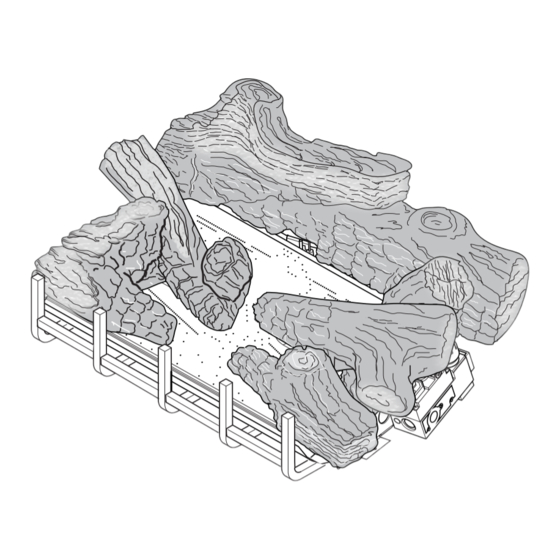
Page 23: Charred Timber Log Placement
Never add additional logs or embellishments such as pine cones, vermiculite or rock wool to the heater. Only use the logs and TPB18-RW (rock wool) supplied with the unit. Failure to position the parts in accordance with diagrams below or to use only parts specifically approved for this heater may result in property damage or personal injury. - Page 24 LOG PLACEMENT 3. Place left base log (#3) on two pins on left side of grate. see Figure 21. Left Base Log (#3) Pins Figure 21 - Installing Left Base Log (#3) Right Front Log (#4) 4. Place right front log (#4) on two pins on bottom right side of grate. see Figure 22.
- Page 25 LOG PLACEMENT 5. Place right end of left top log (#5) on bottom center grate pin. Place left end of left top log (#5) on top of the left base log. see Figure 23. Left Top Log (#5) Bottom Center Pin Figure 23 - Installing Left Top Log (#5) 70D0004...
- Page 26 Right Base Figure 25 - Installing Right Top Log (#6) PLACING ROCk WOOL After installing logs, place TPB18-RW (Rock Wool) in dime-size pieces evenly across the burner surface in between the logs. Do not add additional rock wool. see Figure 26 for the ap- proximate area to place rock wool.
-
Page 27: Riser And Steel Bar Installation
RISER AND STEEL BAR GRATE INSTALLATION OPTIONAL RISER INSTALLATION An optional riser is available. Place the riser in your firebox or fireplace in the desired location. Place burner on riser. Attach burner to riser with two screws provided. see Figures 27 and 28. Screws Riser Screw Holes Figure 28 - Burner Installed on Riser... -
Page 28: Optional Cast Iron Grate And Andirons Installation
OPTIONAL CAST IRON GRATE AND ANDIRON INSTALLATION CAST IRON GRATE INSTALLATION An optional cast iron grate is available. The grate will set in front of the riser on the fireplace floor. The grate may be used with or without the riser. see Figure 31. Legs Cast Iron Grate... -
Page 29: Flame Appearance
FLAME APPEARANCE PLACING THE DECORATIVE ROCk DO NOT sprinkle volcanic rock on the logs, around the pilot, or on or near burners. This may cause sooting. Place volcanic rock only on the floor of the fireplace. During initial operation of the new heater, burning logs will give off a paper burning smell and orange flames will be present. -
Page 30: Checking Burner Flames
CHECkING THE BURNER FLAME In normal operation at full rate after 15 minutes, the following flame appearances should be observed: Figure 35 - Correct Appearance of Rear Flames of Charred Timber Burner will have a random pattern of yellow flames as shown in Figure 35. There should be glowing embers on the front burner. -
Page 31: Operating Instructions
OPERATING INSTRUCTIONS FOR YOUR SAFETY READ BEFORE LIGHTING If you do not follow these instruction exactly, a fire or explosion may result causing property damage, personal injury or loss of life. A. This appliance is equipped with a piezo ignition device which lights the pilot. If piezo is not working properly see Match lighting instructions, page 33. -
Page 32: Milli-Volt Control Lighting Instructions
OPERATING INSTRUCTIONS MILLI-VOLT CONTROL LIGHTING INSTRUCTIONS 1. STOP! Read the safety information label. 2. Make sure the manual shutoff valve is fully open. 3. This gas log set is equipped with an ignition device (piezo) which automatically lights the pilot. If piezo ignitor does not light the pilot, refer to instructions for Match lighting instructions, page 33. -
Page 33: Match Lighting Instructions
OPERATING INSTRUCTIONS CLEANING AND SERVICING MATCH LIGHTING INSTRUCTIONS 1. Remove any items necessary for easy access to the pilot (for example: logs, screens, etc.). 2. Follow appropriate lighting instructions found previously. Instead of pushing and releasing the piezo button, light a match and hold the flame to the end of the pilot and ignite the pilot. 3. -
Page 34: Troubleshooting
TROUBLESHOOTING Turn appliance OFF and allow to cool before servicing. Only a qualified service person should service and repair the heater. Note: All troubleshooting items are listed in order of operation. OBSERVED PROBLEM POSSIBLE CAUSE REMEDY When ignitor button is 1. - Page 35 TROUBLESHOOTING If the gas quality is bad, your pilot may not stay lit, the burners may produce soot and the heater may backfire when lit. If the gas quality or pressure is low, contact your local gas supplier immediately. OBSERVED PROBLEM POSSIBLE CAUSE REMEDY ODS/pilot lights, but flame 1.
-
Page 36: Replacement Parts
REPLACEMENT PARTS BURNER ASSEMBLY Failure to position the parts in accordance with these diagrams or failure to use only parts specifically approved with this appliance may result in property damage or personal injury. 70D0004... -
Page 37: Replacement Parts List
REPLACEMENT PARTS LIST REPLACEMENT PARTS ARE AVAILABLE THROUGH YOUR RETAILER. BURNER ASSEMBLY TPB18 TPB24 TPB30 Ref. Description Qty. Natural Propane Natural Propane Natural Propane 1. Piezo Ignitor 14D0503 14D0503 14D0503 14D0503 14D0503 14D0503 2. Piezo Wire 00K0632 00K0632 00K0632 00K0632 00K0632 00K0632 3. -
Page 38: Logs
REPLACEMENT PARTS LIST REPLACEMENT PARTS ARE AVAILABLE THROUGH YOUR RETAILER. CHARRED TIMBER LOGS Item Description CTCL18 CTCL24 CTCL30 Rear Log 70D0121 70D0031 70D0221 Right Base Log 70D0122 70D0032 70D0222 Left Front Base Log 70D0123 70D0033 70D0223 Right Front Log 70D0127 70D0037 70D0227 Left Top Log... - Page 39 NOTES 70D0004...
- Page 40 70D0004...
- Page 41 70D0004...
-
Page 42: Massachusetts Residence Only
Massachusetts Residents Only — Please read and follow these special requirements NOTE REGARDING VENTED PRODUCTS detector with an alarm shall be installed. This product must be installed by a licensed plumber or 2. Approved Carbon Monoxide Detectors. Each carbon gas fitter when installed within the Commonwealth of monoxide detector as required in accordance with the above Massachusetts. -
Page 43: Warranty
After installation, if any of the components manufactured by MHSC in the appliance are found to be defective in materials or workmanship, MHSC will, at its option, replace or repair the defective components at no charge to the original owner. MHSC will also pay for reasonable labor costs incurred in replacing or repairing such components for a period of two years from the date of installation. - Page 44 MHSC 149 Cleveland Drive • Paris, Kentucky 40361 www.mhsc.com...
Need help?
Do you have a question about the TPB18 and is the answer not in the manual?
Questions and answers