
Related Manuals for Meyer Sound 700-HP


Summary of Contents for Meyer Sound 700-HP
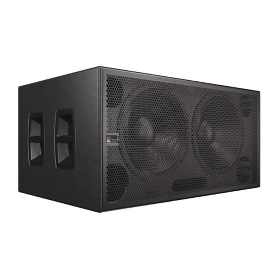
- Page 1 OPERATING INSTRUCTIONS CONCERT SERIES 700-HP UltraHigh-Power Subwoofer Keep these important operating instructions. Check www.meyersound.com for updates.
- Page 2 The contents of this manual are furnished for informational purposes only, are subject to change without notice, and should not be construed as a commitment by Meyer Sound Laboratories Inc. Meyer Sound assumes no responsibility or liability for any errors or inaccuracies that may appear in this manual.
-
Page 3: Important Safety Instructions
2. Keep these instructions. 12. Use only with the caster rails or rigging specified by 3. Heed all warnings. Meyer Sound, or sold with the loudspeaker. Handles 4. Follow all instructions. are for carrying only. 5. Do not use this loudspeaker near water. -
Page 4: Safety Summary
Vuelva a conectar la alimentacion without using weather protection par du personnel qualifié et agréé de voltaje una vez efectuadas equipment from Meyer Sound. par le constructeur. todas las interconexiones de Do not allow water or any señalizacion de audio. -
Page 5: Table Of Contents
Activity LED (Green) User Interface CHAPTER 5: System Integration Using the 700-HP with Meyer Sound Loudspeakers Using the 700-HP with Concert Series and UltraSeries Loudspeakers Daisy-Chained Adding an LD-1A/LD-2 Line Driver Using the 700-HP with M Series Loudspeakers Adding an LD-3 Compensating Line Driver... - Page 6 APPENDIX A: Optional Rain Hood and Amplifier Replacement Installation and Tilt for Weather-Protected Loudspeakers Using the Rain Hood Removing the HP-2/700 Amplifier Replacing the HP-2/700 Amplifier Removing the HP-2/700 Amplifier (with Rain Hood) Replacing the HP-2/700 Amplifier and Rain Hood APPENDIX B: 700-HP Specifications...
-
Page 7: Introduction
Chapter 3: Amplification and Audio will help you under- stand and harness the power of the 700-HP amplifier and audio systems. Amplifier specifications, connectivity, limit- ing and cooling system components are all covered. - Page 8 INTRODUCTION...
-
Page 9: Chapter 1: 700-Hp Ultrahigh-Power Subwoofer
The skids align with slots on the cabinet’s of the 700-HP are created as a symbiotic system that opti- upper surfaces ensuring secure, aligned stacking. For maxi- mizes performance and maximizes its tremendous power. -
Page 10: Meyer Sound Tm Arrays
TM Arrays are comprised of four overhead, center subwoofer arrays that deliver uniform, low-frequency coverage for in-the-round live sound events. The high efficiency of the design allows for installations with fewer subwoofers. Sound Field Figure 1.3. Meyer Sound TM Array top view in MAPP Online... -
Page 11: Chapter 2: Power Requirements
Ground in the above example). AC POWER The 700-HP subwoofer uses a NEMA L6-20P, an IEC 309 When AC power is applied to the 700-HP subwoofer, the male power connector or a multipin VEAM connector and Intelligent AC™ power supply automatically selects the complies with worldwide product safety standards. -
Page 12: Current Requirements
39 A pk 20 A pk 45 A pk If the 700-HP subwoofer shuts down due to either low or term peak high voltage, its power supply automatically turns on again after three seconds if the voltage has returned to either nor- mal operating window. -
Page 13: Power Connector Wiring Conventions
Meyer Sound offers the VIM-3 (VEAM interface module) to distribute power, audio, and RMS to 700-HP subwoofers fitted with VEAM connectors, as shown in Figure 2.5. Figure 2.2. The 700-HP subwoofer user rear panel with L6-20 power connector Figure 2.5. VIM-3 module, front (top) and rear (bottom) -
Page 14: Electrical Safety Issues
Pay close attention to these important electrical and safety issues. CAUTION: Do not use a power cord adapter to drive the 700-HP subwoofer from a stan- dard three-prong Edison outlet since that connector is rated for only 15 amps (NEMA 5-15R; 125 V AC max.). -
Page 15: Chapter 3: Amplification And Audio
This chapter will help you under- cause hum. stand and harness the power of the 700-HP amplifier and audio systems. Use standard audio cables with XLR connectors for bal- The rear panel of the 700-HP (Figure 3.1) provides AC... -
Page 16: 700-Hp Interconnections
AC power for the source of the problem. 700-HP cabinets are flown in an array. A ring/stud fitting is provided on the rear of the 700-HP Meyer Sound LD-1A, LD-2 and LD-3 line drivers are loudspeaker to act as a strain relief for cabling. Using this... -
Page 17: 700-Hp Amplifier Cooling System
TruPower limiting activity is indicated by the LED on the amplifier’s user panel. In addition to TPL limiting the 700-HP also includes a peak 700-HP AMPLIFIER COOLING SYSTEM limiter. When engaged, the peak limiter prevents signal... - Page 18 700-HP shuts down again after cooling and re- applying AC power, contact Meyer Sound for repair information. Despite the 700-HP’s filtering, extensive use or a dusty op- erating environment can allow dust to accumulate along the path of the airflow, preventing normal cooling. To prevent...
-
Page 19: Chapter 4: Rms Remote Monitoring System (Optional)
Node Name. RMS allows you to monitor amplifier voltages, limiting A 700-HP is identified using the RMS software by activat- activity, power output, temperature, fan and driver status, ing the “service” function; an icon will show up on the RMS warning alerts, and other key data for up to 62 loudspeak- screen corresponding to its Node Name (Figure 4.2). -
Page 20: Service Button
RMS, and have no effect on the If the installation pattern changes completely, a new screen acoustical and/or electrical activity of the 700-HP it- panel can be built. If a subset of installed loudspeakers will self – unless MUTE or SOLO is enabled at the board be used for a subsequent event, only selected loudspeak- and from the RMS software. -
Page 21: Chapter 5: System Integration
700-HP (MILO, MSL-4, M2D, CQ-1, etc.) Sound loudspeakers are coplanar, this usually occurs at a The configuration of the system, whether flown or ratio of two loudspeakers to each 700-HP. This is the con- ground stacked figuration commonly used in small systems. -
Page 22: Adding An Ld-1A/Ld-2 Line Driver
If the 700-HP subwoofers are placed more than 4 feet away from the M Series shifts that can cause cancellations in the overlap area. array, you may need to set the 700-HP and the M Series loudspeakers to opposite polarities. NOTE:... -
Page 23: Using The 700-Hp With The 650-Psubwoofer
HP subwoofers should be fed from the DSP in order to keep their delay time the same. Otherwise, you may experience * Unlike the matched sensitivity of the M2D and M2D-Sub, the 700-HP is +6 dB more sensitive than the M2D/M2D-Sub. - Page 24 CHAPTER 5 In no case should a filter higher than 2 order be used. The additional phase shift introduced deteriorates the impulse response and higher roll-off does not improve crossover interaction. In fact, it is highly recommended that the crossover/filter be set to emulate the low-cut LD-1A/LD-2 characteristics themselves, as shown in Table 5.4.
-
Page 25: Chapter 6: System Design And Integration Tools
– including basic system delay and equalization Residing on your computer, MAPP Online facilitates con- settings. Its accurate, high-resolution predictions eliminate figuring arrays of a wide variety of Meyer Sound products unexpected onsite adjustments and coverage problems. and, optionally, defines the environment in which they will... -
Page 26: Sim Measurement System
Optimizing loudspeaker arrays Source Independent Measurement Technique The SIM audio analyzer can also be used in the following The SIM audio analyzer implements the Meyer Sound applications: source independent measurement technique, a dual-chan- nel method that accommodates statistically unpredictable Microphone calibration and equalization... -
Page 27: Chapter 7: Quickfly Rigging
Never use MTG-700 rigging links to connect 700-HP subwoofers. MRK-700 RIGGING KIT The MRK-700 rigging kit is required to attach the 700-HP ultrahigh-power subwoofer to the MTG-700 top grid. This optional rigging kit is available installed at the factory or as... -
Page 28: Mtg-700 Multipurpose Grid
MTG-700 top grid, and secured with the 3/8" x 1.125" QRPs (Figure 7.5). Figure 7.3. Flying a 700-HP array is easily achieved with the MTG-700 top grid (3 to 2 corner/center point pickup configuration shown). -
Page 29: Mcf-700 Caster Frame
TIP: You can also transport the MTG-700 attached to the top 700-HP on a stack. Figure 7.7. MCF-700 caster frame supporting 3 700-HP subwoofers in a The MCF-700’s rugged steel frame allows the use of a ground-stack forklift. - Page 30 CHAPTER 7...
-
Page 31: Appendix A: Optional Rain Hood And Amplifier Replacement
It is provided to protect the loudspeaker’s electronics from direct exposure If you need to remove the amplifier from a 700-HP loud- to rainfall. Before using the 700-HP loudspeaker, open the speaker, perform the following steps: rain hood as described in the following procedure. -
Page 32: Removing The Hp-2/700 Amplifier (With Rain Hood)
Replacing the HP-2/700 Amplifier and Rain Hood Perform the following steps to replace amplifier and rain hood: 1. Gently slide the amplifier partially back into 700-HP and connect the loudspeaker connector. 2. With the wires properly connected, slide the amplifier all the way into its cabinet. -
Page 33: Appendix B: 700-Hp Specifications
APPENDIX B APPENDIX B: 700-HP SPECIFICATIONS ACOUSTICAL Operating frequency range 28 Hz - 150 Hz Note: Recommended maximum operating frequency range. Response depends upon loading conditions and room acoustics. Frequency response 30 Hz - 125 Hz ±4 dB Note: Free field, measured with 1/3 octave frequency resolution at 4 meters. - Page 34 50.90" w x 22.50" h x 30.00" d (1293 mm x 572 mm x 762 mm) Weight 204 lbs (92.53 kg) Weight with rigging 259 lbs (117.48 kg) 700-HP 700-HP with rigging 30.00" 30.00" [762 mm] [762 mm] 30.00" 30.00"...
- Page 36 Meyer Sound Laboratories Inc. 2832 San Pablo Avenue Berkeley, CA 94702 www.meyersound.com © 2004 Meyer Sound Laboratories Inc. T: +1 510 486.1166 F: +1 510 486.8356 700-HP Operating Instructions, PN 05.137.094.01 A2...
Need help?
Do you have a question about the 700-HP and is the answer not in the manual?
Questions and answers