Table of Contents
Advertisement
Quick Links
Advertisement
Table of Contents

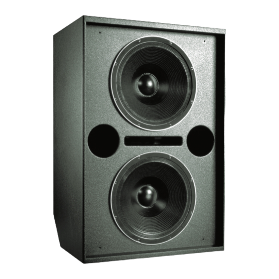
Summary of Contents for Meyer Sound 650-P
- Page 2 U U L L U U L L LISTED 3K59 ® ® COMMERCIAL AUDIO SYSTEM...
-
Page 3: Voltage Requirements
650-P to be used in the US, Eu- If the 650-P shuts down due to either low or high voltage, rope, or Japan without manually setting a voltage switch. -
Page 4: Current Requirements
Safety Issues Current Requirements Pay close attention to these important electrical and The 650-P presents a dynamic load to the AC mains safety issues. which causes the amount of current to fluctuate be- tween quiet and loud operating levels. Since different... -
Page 5: Power Connector Wiring Conventions
For example, since the input (chassis) impedance of a single 650-P is 10 kOhms, cascading 20 650-Ps produces a balanced input impedance of 500 Ohms. If a 150 Ohm source is used, the 500 Ohm load results in a 2.28 dB loss. -
Page 6: Fans And Cooling System
The • accumulation of dust in the cooling system path; 650-P operates safely if the Exc. Clamp LED is on for no • driver failure. longer than two seconds, and off for at least one second. - Page 7 Placement One of the most important factors governing subwoofer response is their placement relative to adjacent sur- faces. Subwoofers gain significant power by coupling, or loading, with nearby floors and walls. Half-space loading describes a speaker coupling with one surface. Subs Designing a full-range system requires an understanding placed on the floor benefit from half-space loading, of how subwoofers respond when grouped together,...
- Page 8 CP-10 EQ sent to the Sub output (for the 650-P), and above (1 Channel) 80 Hz to the DS-2 output. When the 650-P is used loop without the DS-2P, the switch should be out, which sends a full-range signal to both the DS-2...
- Page 9 Lo Cut filter in to minimize the overlap in frequency system. The DS-2 & Sub Crossover switch should be response with the DS-2P and 650-P. Set the 650-P to the out. opposite polarity to the MSL-4 and DS-2P.
-
Page 10: Verifying Driver Polarity
The TPL LED can indicate serious driver problems, if 2. Connect a signal source to the loudspeaker and interpreted correctly. If one 650-P in a system exhibits note the frequency response. substantially more TPL activity than others receiving the same audio signal, then one or both drivers in that unit may have a short circuit. - Page 11 • To reduce the risk of electric shock, disconnect the loud- • Pour réduire le risque d’électrocution, débrancher la speaker from the AC mains before installing audio cable. prise principale de l’haut-parleur, avant d’installer le Reconnect the power cord only after making all signal câble d’interface allant à...
- Page 12 Notes...
- Page 14 Front Side...
- Page 15 Notes...


Need help?
Do you have a question about the 650-P and is the answer not in the manual?
Questions and answers