
Related Manuals for Meyer Sound 500-HP


Summary of Contents for Meyer Sound 500-HP
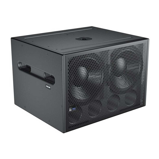
- Page 1 OPERATING INSTRUCTIONS 500-HP Compact High-Power Subwoofer Keep these important operating instructions. Check www.meyersound.com for updates.
- Page 2 The contents of this manual are furnished for informational purposes only, are subject to change without notice, and should not be con- strued as a commitment by Meyer Sound Laboratories Inc. Meyer Sound assumes no responsibility or liability for any errors or inaccura- cies that may appear in this manual.
-
Page 3: Important Safety Instructions
2. Keep these instructions. 12. Use only with the caster rails or rigging specified by 3. Heed all warnings. Meyer Sound, or sold with the loudspeaker. Handles are 4. Follow all instructions. for carrying only. 5. Do not use this loudspeaker near water. -
Page 4: Safety Summary
SAFETY SUMMARY English Ne pas installer l’haut-parleur dans un Um ein Überhitzen dem Lautsprecher endroit où il y a de l’eau ou une humid- zu verhindern, das Gerät vor direkter To reduce the risk of electric shock, dis- ité excessive. Sonneneinstrahlung fernhalten und connect the loudspeaker from the AC nicht in der Nähe von wärmeabstrahl-... -
Page 5: Table Of Contents
Audio Connections with VEAM Cabling Audio Input Modules Amplifier Cooling System Chapter 4: Integrating 500-HP Subwoofers Integrating 500-HP Subwoofers with Meyer Sound Loudspeaker Systems Daisy-Chaining 500-HP Subwoofers with Loudspeakers Driving 500-HP Subwoofers and Loudspeakers with Line Drivers Digital Signal Processors and 500-HP subwoofers ®... - Page 6 CONTENTS...
-
Page 7: Chapter 1: Introduction
HOW TO USE THIS MANUAL INTRODUCING THE 500-HP SUBWOOFER Make sure to read these operating instructions in their The 500-HP is a compact, high-output subwoofer that inte- entirety before configuring a loudspeaker system with grates smartly with other Meyer Sound loudspeakers, 500-HP subwoofers. - Page 8 (or safely stowed). A wide range of splay angles and configurations is achieved with different combi- The 500-HP boasts an operating frequency range of 35 Hz nations of front, center, and back positions for the to 140 Hz and a peak SPL of 135 dB. Designed and manu-...
- Page 9 500-HP OPERATING INSTRUCTIONS 500-HP Groundstacked with M’elodies MG-M’elodie Grid with 500-HP and M’elodie Array...
- Page 10 CHAPTER 1: INTRODUCTION...
-
Page 11: Chapter 2: Power Requirements
AC power distribution system, ensuring that AC line polarity is preserved and that all grounding The user panel on the back of the 500-HP includes the fol- points are connected to a single node or common point lowing PowerCon AC connectors: using the same cable gauge as the neutral and line cables. -
Page 12: Power Connector Wiring
Connect the AC Loop Output of the first 500-HP to tem be properly grounded. the AC Input of the second 500-HP, and so forth. The AC Loop Output uses a PowerCon3 AC mains locking connec- tor that prevents accidental disconnections. -
Page 13: 500-Hp Current Requirements
Powering Up the 500-HP maximum rms current during a period of at least 10 sec- When AC power is applied to the 500-HP, its Intelligent AC™ onds. The Maximum Long-Term Continuous Current is power supply automatically selects the correct operating... -
Page 14: Electrical Safety Issues
NOTE: For best performance, the AC cable ■ Use the cable ring on the rear of the 500-HP subwoofer voltage drop should not exceed 10 V, or to reduce strain on the connected AC power and audio 10 percent at 115 V and 5 percent at 230 V. Make cables. -
Page 15: Chapter 3: Amplification And Audio
The user panel on the back of the 500-HP has two slots for modules. The top slot contains an audio input module (described in this chapter). The bottom slot is reserved for the optional RMS module, used for connecting to the RMS remote monitoring system (see Chapter 6, “The RMS... - Page 16 Connect by separate amplifier channels that are each routed to a sin- the Loop output of the first 500-HP to the Input of the sec- gle limiter. When a safe power level is exceeded in either ond 500-HP, and so forth.
- Page 17 6 dB. This is useful when distributing left and right channels from a stereo signal to a single 500-HP with- Looping, Polarity, and Attenuating Audio Input Module out requiring external level control.
-
Page 18: Amplifier Cooling System
CHAPTER 3: AMPLIFICATION AND AUDIO AMPLIFIER COOLING SYSTEM The amplifier for the 500-HP uses natural convection for cooling at low to moderate audio levels; for high audio lev- els, it uses Meyer Sound’s proprietary QuietCool™ fan tech- nology to prevent overheating. The QuietCool fan only engages at high audio levels, making it virtually inaudible. -
Page 19: Chapter 4: Integrating 500-Hp Subwoofers
500-HP attaches to the MG-M’elodie rigging TIP: MAPP Online Pro™ can be used to accu- grid; the M’elodies attach to the bottom of the 500-HP via rately predict the appropriate loudspeaker the GuideALinks, which support both uptilt and downtilt for deployment and subwoofer integration for loud- the flown loudspeakers. -
Page 20: Daisy-Chaining 500-Hp Subwoofers With Loudspeakers
LOUDSPEAKERS WITH LINE DRIVERS subwoofer in free space (suspended). Using a line driver with dedicated low and mid-hi outputs (like Meyer Sound’s LD-1A and LD-2) to drive a loudspeaker Flying 500-HP Subwoofers system with 500-HP subwoofers allows adjustments to the gain and polarity of each sub-system. -
Page 21: Digital Signal Processors And 500-Hp Subwoofers
500-HP OPERATING INSTRUCTIONS measurement system like Meyer Sound’s SIM 3 is rec- THE GALILEO LOUDSPEAKER MANAGEMENT SYSTEM ommended to determine appropriate delay and polarity settings. Meyer Sound’s Galileo ® loudspeaker management system is a comprehensive solution for driving and aligning loud-... - Page 22 CHAPTER 4: INTEGRATING 500-HP SUBWOOFERS...
-
Page 23: Chapter 5: Quickfly Rigging
Use mounting hardware appropriate for the surface attaching to GuideALinks — from the MG-M’elodie multipur- where the loudspeaker will be installed. pose grid or from another 500-HP — when the subwoofer is Make sure bolts and eyebolts are tightened securely. ■... -
Page 24: Groundstacking 500-Hps
Position B Position A Stowed Position 500-HP GuideALink Positions 500-HP GuideALinks are secured at the top and bottom of the rigging frames with the 10 included quick-release pins. Quick-release pins Groundstacked 500-HPs Table 3: GuideALink Positions for Groundstacked 500-HPs... -
Page 25: The Mg-M'elodie Grid
500-HP. When groundstacking a M’elodie above a 500-HPs. 500-HP, the M’elodie’s GuideALinks should be attached to the front and middle slots of the 500-HP. The M’elodies can be groundstacked at angles from +5 degrees (downtilt) to THE MG-M’ELODIE GRID –5 degrees (uptilt) in 1-degree increments. - Page 26 The MG-M’elodie GuideALinks can also be attached to the MG-M’elodie grid, make sure to use the quick- rear and middle slots of the 500-HP. This configuration can release pins with the red or blue buttons. Do not use be used with curved arrays so the array’s center of gravity is the quick-release pins with the black buttons, closer to the middle of the grid.
-
Page 27: 500-Hp With Flown Loudspeakers
500-HP, including the GuideALink positions and attach- ment points. When the MG-M’elodie’s front and rear GuideALinks are set to position A, the attached 500-HP is flown at 0 degrees. Table 6: MG-M’elodie and 500-HP Configurations Angles of +5 and –5 degrees are also possible by adjusting MG-M’elodie GuideALink Posi-... - Page 28 When flying 500-HPs, the front and rear GuideALinks are Rear Middle Front Flown attached to the front and rear slots of the flown 500-HP (the (Attached to (Attached to 500-HP middle GuideALinks are not used). The most common angle Rear Slot) Front Slot) for flown 500-HPs is 0 degrees.
- Page 29 500-HP OPERATING INSTRUCTIONS 500-HPs with Flown M’elodies Table 8: 500-HP GuideALink Positions for Flown M’elodies 500-HPs can be flown within M’elodie arrays to supplement GuideALink Positions Angle for and extend low-frequency headroom. In these mixed arrays, Back Middle Front Flown...
-
Page 30: 500-Hp Cardioid Arrays
The heavy-duty MCF-500 caster frame can transport stacks safely suspended from a 500-HP. For MG-M’elodie load rat- of up to three 500-HP subwoofers (fitted with or without ings, see “MG-M’elodie Grid Load Ratings” on page 26 MRF-500 rigging frames). The caster frame can also be used for groundstacking 500-HPs, though this option Table 9: 500-HP Load Ratings for M’elodie Arrays... -
Page 31: Pole-Mount Receptacle
500-HP Pole-Mount Receptacle The following UltraSeries loudspeakers can be mounted on top of the 500-HP. Make sure that the pole and pole-mount adapter can support the weight of the mounted loudspeak- ers and that they are installed according to the manufac- turer’s instructions. - Page 32 CHAPTER 5: QUICKFLY RIGGING...
-
Page 33: Chapter 6: The Rms Remote Monitoring System
CHAPTER 6: THE RMS REMOTE MONITORING SYSTEM An optional RMS remote monitoring system module can be THE RMS SOFTWARE installed in the 500-HP, allowing it to be connected to an The optional RMS software provides extensive system sta- RMS network. RMS allows real-time monitoring of multiple... -
Page 34: The Rms Module
The RMS module is installed in the bottom slot of the user be customized to suit your needs. Loudspeaker data is panel on the back of the Meyer Sound loudspeaker. The updated 2–5 times per second. Individual loudspeakers can RMS user panel has three LEDs, two buttons, and two Net- be physically identified with the Wink option in RMS, which work connectors. -
Page 35: Resetting The Rms Module
500-HP OPERATING INSTRUCTIONS Reset Button Pressing the Reset button causes the RMS module’s firm- ware to reboot; this will not affect whether the loudspeaker is commissioned (which is stored in flash memory). You can simultaneously press the Reset and Service buttons to reset the RMS module and decommission the loudspeaker from the network (see “Resetting the RMS Module”... - Page 36 CHAPTER 6: THE RMS REMOTE MONITORING SYSTEM...
-
Page 37: Chapter 7: System Design And Integration Tools
Meyer Sound’s patented online acoustical prediction tool, are based on 360 1/48th-octave-band measurements taken and SIM 3, a comprehensive system for measurement and with a SIM audio analyzer in the Meyer Sound anechoic analysis. chamber. The extraordinary consistency between Meyer... -
Page 38: The Sim ® 3 Measurement System
The MAPP Online Pro client software is regularly upgraded ■ Measuring propagation delays between subsystems to to add support for the latest Meyer Sound loudspeakers, as determine appropriate polarities and delay times well as to add feature enhancements. Most upgrades are Measuring variations in frequency response caused by ■... -
Page 39: Appendix A: Optional Veam Multipin Connector
APPENDIX A: OPTIONAL VEAM MULTIPIN CONNECTOR The 500-HP subwoofer requires a grounded outlet. It is very For complete VEAM wiring conventions and pin-outs for AC, important that the system be properly grounded in order to audio, and RMS connections, refer to the Meyer Sound doc- operate safely and properly. - Page 40 APPENDIX A: OPTIONAL VEAM MULTIPIN CONNECTOR...
-
Page 41: Appendix B: Optional Rain Hood
[154 mm] and LEDs to be visible. THE 500-HP RAIN HOOD KIT CONTENTS 12.49 [317 mm] The 500-HP rain hood kit (PN 40.187.059.01) includes the following parts: 500-HP Rain Hood Kit Part Part Number Quant. - Page 42 APPENDIX B: OPTIONAL RAIN HOOD 3. Attach the user panel rain hood assembly to the user panel, slipping it under the flange at the top of the panel and securing it to the bottom with the two lock pins. User panel rain hood assembly Lock...
-
Page 43: Appendix C: Specifications
APPENDIX C: SPECIFICATIONS 500-HP COMPACT HIGH-POWER SUBWOOFER SPECIFICATIONS 500-HP Specifications ACOUSTICAL Operating Frequency 35 Hz – 140 Hz Range Note: Recommended maximum operating frequency range. Response depends on loading condi- tions and room acoustics. Frequency Response 36 Hz – 130 Hz ±4 dB Note: Measured free field with 1/3 octave frequency resolution at 4 meters. - Page 44 APPENDIX C: SPECIFICATIONS 500-HP Specifications AMPLIFIER Type Two-channel complementary MOSFET output stages (class AB/H) Output Power 1800 W total (2 x 900 W) Note: Wattage rating based on the maximum unclipped burst sine-wave rms voltage the amplifier will produce into the nominal load impedance; both channels 42 V rms into 2 ohms.
- Page 45 [674 mm] 18.23 [463 mm] 500-HP Dimensions [286 mm] 8.50 [216 mm] Ø1.52 22.50 [Ø39 mm] [572 mm] 18.00 [457 mm] 15.45 22.18 [392 mm] [563 mm] 28.27 26.47 [718 mm] [672 mm] 18.23 [463 mm] 500-HP Dimensions with Rigging...
- Page 46 APPENDIX C: SPECIFICATIONS MCF-500 CASTER FRAME SPECIFICATIONS MCF-500 Specifications PHYSICAL Materials and Premium birch plywood base with black finish; steel-reinforced brackets; high-density polyethylene Components protective bumpers on all four sides. Dimensions 30.22" w x 6.63" h x 23.96" d (768 mm x 168 mm x 609 mm) Weight Weight 39 lbs (17.69 kg) 30.22...
- Page 48 Meyer Sound Laboratories Inc. 2832 San Pablo Avenue Berkeley, CA 94702 www.meyersound.com © 2009 Meyer Sound. All rights reserved. T: +1 510 486.1166 500-HP — 05.187.045.01 A F: +1 510 486.835...
Need help?
Do you have a question about the 500-HP and is the answer not in the manual?
Questions and answers