Rotel RA-1062 Technical Manual
Hide thumbs
Also See for RA-1062:
- Owner's manual (54 pages) ,
- Owner's manual (46 pages) ,
- User manual (10 pages)
Advertisement
Quick Links
T echnical
Manual
Table of Contents
Specification....................................... 1
Parts List ............................................ 2~7
Adjustment.......................................... 8
Case Outlines ..................................... 9 ~ 10
PCB Assembly ................................... 11
Schematic Diagram ............................ 12~13
Specification
Continuous Power Output
Total Harmonic Distortion (20 Hz - 20 kHz)
Intermodulation Distortion(60 Hz : 7 kHz, 4:1) < 0.03% at rated power, 1/2 power or 1 watt
Frequency Response
Damping Factor (20 - 20,000 Hz. 8 ohms)
Line Input Sensitivity / impedance
Phono (MM) Input Sensitivity / impedance
Line Input Overload
Phono Input Overload
Preamplifier Output / Impedance
Signal to Noise Ratio (IHF " A" weighted)
Power Requirements
Power Consumption
Dimensions (W x H x D)
Front Panel Height
Weight (net)
SHINSEN-BLD. 4F 10-10 SHINSEN-CHO, SHIBUYA-KU,
TOKYO 150-0045, JAPAN
Quality Uncompromised
Phono Input
Line Level Inputs
®
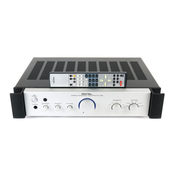
STEREO INTEGRATED AMPLIFIER
RA-1062
60 watts/channel
(20 - 20 kHz, < 0.03%, 8 ohms)
< 0.03% at rated power, 1/2 power, or 1 watt
20 Hz - 15 kHz, +/- 0.2 dB
10 Hz - 100 kHz, +l, -3dB
150
160 mV / 24 kOhms
2.4 mV / 47 kOhms
5 v
170 mV
1 V / 470 ohms
>95 dB
USA: 115 Volts, 60 Hz
EC: 230 Volts, 50 Hz
300 Watts
430 x 92 x 355 mm
17 x5
x 14 inches
5/8
3/16
80 mm / 3
inches
7.8 kg, 17.2 lbs.
Serial. NO.
Beginning
Y-369A0307/pdf
Advertisement

Related Manuals for Rotel RA-1062


Summary of Contents for Rotel RA-1062
-
Page 1: Table Of Contents
Quality Uncompromised ® T echnical STEREO INTEGRATED AMPLIFIER RA-1062 Manual Table of Contents Specification........1 Parts List ..........2~7 Adjustment.......... 8 Case Outlines ........9 ~ 10 PCB Assembly ........11 Schematic Diagram ......12~13 Specification Continuous Power Output 60 watts/channel (20 - 20 kHz, <... - Page 2 WARNING: TO REDUCE THE RISK RISK OF ELECTRIC SHOCK INTEGRATED AMPLIFIER OF FIRE OR ELECTRICAL SHOCK, DO NOT OPEN MODEL NO. RA-1062 DO NOTEXPOSE THIS EQUIPMENT WARNING: SHOCK HAZARD - DO NOT OPEN POWER CONSUMPTION: 300W TO RAIN OR MOISTURE...
-
Page 3: Parts List 1/4
DESCRIPTION 016 E-1355A00 PCB ASSY (HEAD PHONE) 501 E-1355-A PCB ASSY 065 H1038SN20S HEAD PHONE JACK (YKB26-5261) 068 B3B-EH CONNECTOR WAFER 3P RA-1062 016E-1379A00 PCB ASSY (PHONO) 501 E-1379 PCB ASSY IC451 031 NE5532AN IC (OPE DUAL) C463,464 041 TVX1E101... - Page 4 RA-1062 Parts List 2/4 SYMBOL PARTS NO. DESCRIPTION D726-730,905,906 034 T1N4148-86 DIODE 1N4148TAP-50 D909 034 TRD12JST1 ZENER DIODE 12V (AB2) D907,908 034 TRD16JST1 ZENER DIODE 16V (AB2) D723 034 TRD5.6JST1 ZENER DIODE 5.6V (AB2) TH901 034 TTC-503 THERMISTOR 50K F601-604 036 5ST6.3...
- Page 5 RA-1062 Parts List 3/4 SYMBOL PARTS NO. DESCRIPTION R667,668,904 054 1WS1.5KJF MOF RESISTOR 1WS 1.5K (R912) 054 1WS10KJF MOF RESISTOR 1WS 10K (R912) 054 1WS15KJF MOF RESISTOR 1WS 15K R908 054 1WS68JF MOF RESISTOR 1WS 68R R907 054 1WS820JF MOF RESISTOR 1WS 820R...
- Page 6 RA-1062 Parts List 4/4 SYMBOL PARTS NO. DESCRIPTION O T H E R 011 FP-564-B BLACK PANEL ASSY 011 FP-564-S SILVER PANEL ASSY 012 C-4710A01 KNOB 25Φ (BLK) 012 C-4710A02 KNOB 25Φ NO MARK (BLK) 012 C-4711A01 KNOB 43Φ W/LED (BLK) 012 C-4711A01S KNOB 43Φ...
- Page 7 Addendum List for Black and Silver RA1062 SYMBOL PARTS DESCRIPTION 506RA-1062-BK BLACK PANEL ASSY 506RA-1062-SV SILVER PANEL ASSY 011 TF3-01A00 H/S PANEL H80 012C-4710A01 KNOB 25F(BLK) 012C-4710A02 KNOB 25F NO MARK (BLK) 012C-4711A01 KNOB 43F W/LED (BLK) 012C-4711A01S KNOB 43F W/LED (SLV) 012C-4712A01 KNOB 13F(BLK) 012C-4712A01S...
-
Page 8: Adjustment
Adjustment Instruments : DC milli–meter Notes Prior to Bias Adjustment, run about 5minutes with rated output (8 ohms) And warm up Power Transistor and Heat Sink.Set input off. Step Coupling Adjust Adjust for X-1294-01 PCB R639 X-1294-03 PCB VR601 DC milli-voltmeter Reads 5mV X-1294-01 PCB R640 X-1294-02 PCB VR602 Service Note... -
Page 9: Case Outlines
Case Outline 2SA1016K 2SA1376K 2SA1208 2SC536K 2SC2362K 2SC3478A 2SB631K 2SC3708 2SA1507 2SC2910 2SA1345 2SD600K 2SB817 2SD863 2SC3399 2SC3902 2SD1047 NJM2114D NJM78XXFA OPA2604AP TC74HC595AP LB1641 TMP47C400BN-1... - Page 10 Memo...
-
Page 11: Pcb Assembly
RA-1062 PCB Assembly Main PCB 016 X-1294D01~09 Phono PCB 016 E-1379... -
Page 12: Schematic Diagram - 1/2
RA-1062 Schematic Diagram - 1/2... - Page 13 The difference between 016x-1294D01and 016x-1294E01 is we have modified Balance volume position and Master volume position in the circuit. Please refer the attached schematic.
- Page 14 Schematic Diagram -2/2 RA-1062...
Need help?
Do you have a question about the RA-1062 and is the answer not in the manual?
Questions and answers