Table of Contents
Advertisement
Quick Links
T echnical
Manual
Table of Contents
Specification...................................... 1
Parts List ........................................... 2~3
Adjustment........................................ 4
Safety Caution................................... 4
Case Outlines.................................... 5
PCB Assembly .................................. 7~8
Schematic Diagram .......................... 9~12
Specification
Continuous Power Output
Total Harmonic Distortion (20 Hz - 20 kHz)
Intermodulation Distortion(60 Hz : 7 kHz, 4:1) < 0.03% at rated power, 1/2 power or 1 watt
Frequency Response (all inputs)
Damping Factor (20 - 20,000 Hz. 8 ohms)
Input Sensitivity / impedance
Input Overload
Preamplifier Output / Impedance
Signal to Noise Ratio (IHF " A" weighted)
Power Requirements
Power Consumption
Dimensions (W x H x D)
Weight (net)
SHINSEN-BLD. 4F 10-10 SHINSEN-CHO, SHIBUYA-KU,
TOKYO 150-0045, JAPAN
Quality Uncompromised
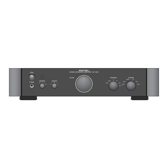
STEREO INTEGRATED AMPLIFIER
®
RA-1060
60 watts/channel
(20 - 20 kHz, < 0.03%, 8 ohms)
< 0.03% at rated power, 1/2 power, or 1 watt
10 Hz - 100 kHz, +l, -3dB
150
160 mV / 33 kOhms
5 v
1 V / 470 ohms
>95 dB
USA: 115 Volts, 60 Hz
EC: 230 Volts, 50 Hz
300 Watts
430 x 92 x 355 mm
17 x5
5/8
x 14 inches
7.8 kg, 17.2 lbs.
Serial. NO.
Beginning
Y-332A-00115C/S-S
Advertisement
Table of Contents

Related Manuals for Rotel RA-1060


Summary of Contents for Rotel RA-1060
- Page 1 Quality Uncompromised ® T echnical STEREO INTEGRATED AMPLIFIER RA-1060 Manual Table of Contents Specification........1 Parts List ........... 2~3 Adjustment........4 Safety Caution........4 Case Outlines........5 PCB Assembly ........7~8 Schematic Diagram ......9~12 Specification Continuous Power Output 60 watts/channel (20 - 20 kHz, <...
-
Page 2: Parts List
Parts List-1 SYMBOL PARTS NO. DESCRIPTION SYMBOL PARTS NO. DESCRIPTION X-1294-01 PCB ASSEMBLY CAPACITOR ELEC.63V22UF Q401-406 032 TA1345 TRANSISTOR(2SA1345) C401 041 UTES1J220-FB C501.502 041 50BGF10M CAPACITOR ELEC.50V10UF Q407-412 032 TC3399 TRANSISTOR(2SC3399) C503.504 044 FSC160V470H CAPACITOR STYROL 160V47PF Q619.620 033 TC3478A-LKU TRANSISTOR(2SC3478A-LKU) C505.506 041 50BGF10M... -
Page 3: Parts List
Parts List-2 SYMBOL PARTS NO. DESCRIPTION SYMBOL PARTS NO. DESCRIPTION R905 053 CR14-472J-A RESISTOR CARBON 4.7K VR601.602 051 SFR001-222 SEMI-FIXED RESISTOR 2.2K R906 053 CR14-103J-A RESISTOR CARBON 10K R907 054 1WS820JF RESISTOR METAL 1W 820R X-1294-04 PCB ASSEMBLY R908 054 1WS68JF RESISTOR METAL 1W 68R D707-712 034 T1N4148-86... -
Page 4: Adjustment
Adjustment Instruments : DC milli–meter Notes Prior to Bias Adjustment, run about 5minutes with rated output (8 ohms) And warm up Power Transistor and Heat Sink.Set input off. Step Coupling Adjust Adjust for X-1294-01 PCB R639 X-1294-03 PCB VR601 DC milli-voltmeter Reads 5mV X-1294-01 PCB R640 X-1294-02 PCB VR602 Service Note... -
Page 5: Case Outlines
Case Outline 2SA1016K 2SA1376K 2SA1208 2SC536K 2SC2362K 2SC3478A 2SB631K 2SC3708 2SA1507 2SC2910 2SA1345 2SD600K 2SB817 2SD863 2SC3399 2SC3902 2SD1047 NJM2114D NJM78XXFA OPA2604AP TC74HC595AP LB1641 TMP47C400BN-1... -
Page 7: Schematic Diagram
Schematic Diagram... -
Page 8: Schematic Diagram
Schematic Diagram...
Need help?
Do you have a question about the RA-1060 and is the answer not in the manual?
Questions and answers