Table of Contents
Advertisement
Quick Links
Download this manual
See also:
User Manual
MANUFACTURED BY:
ISO-9001
AN
6,WU-CHUAN RD.,HSIN-CHUANG TEL: 886-2-2991599 (REP.) FAX: 886-2-2991819, 2991808
(WU-KU INDUSTRIAL ZONE)
TAIPEI HSIEN, TAIWAN
KS-6810
SERIES
TECHNICAL MANUAL
Rev. : Original
POSIFLEX TECHNOLOGY, INC.
ISO-14001
AND
http://www.posiflex.com
http://www.posiflexusa.com
CERTIFIED MANUFACTURER
http://www.posiflex.com.tw
EMAIL: posiflex@posiflex.com.tw
Advertisement
Table of Contents

Related Manuals for POSIFLEX KS-6810 SERIES


Summary of Contents for POSIFLEX KS-6810 SERIES
- Page 1 KS-6810 SERIES TECHNICAL MANUAL Rev. : Original POSIFLEX TECHNOLOGY, INC. MANUFACTURED BY: ISO-9001 ISO-14001 CERTIFIED MANUFACTURER 6,WU-CHUAN RD.,HSIN-CHUANG TEL: 886-2-2991599 (REP.) FAX: 886-2-2991819, 2991808 (WU-KU INDUSTRIAL ZONE) http://www.posiflex.com http://www.posiflex.com.tw TAIPEI HSIEN, TAIWAN http://www.posiflexusa.com EMAIL: posiflex@posiflex.com.tw...
-
Page 2: About This Manual
This manual assists the user especially the software programmer who provides the software system for POS application to utilize the hardware of the KS series which is a member of the POSIFLEX integrated point-of-sale terminal product family. The KS is a compact point-of-sale system that gives... -
Page 3: Table Of Contents
TABLE OF CONTENTS OVERVIEW ............................1 SCOPE..............................1 FEATURES ............................1 OPTIONAL ITEMS..........................2 GENERAL SPECIFICATION ......................3 SYSTEM ............................. 3 POWER SOURCE..........................3 SYSTEM POWER ON/OFF CONTROL .................... 3 12VDC POWER SUPPLY INTO SYSTEM..................3 OVERALL POWER OUTPUT LIMITS ..................... 4 INPUT / OUTPUT PORTS........................ - Page 4 MODEM RING UP ........................20 LAN WAKE UP ..........................20 POSIFLEX TOOLS ........................... 21 POSIFLEX MSR MANAGER ......................21 POSIFLEX USB TOUCH MANAGER ..................25 HARDWARE DETAILS........................28 MAIN BOARD (KS-6810) ........................ 28 COMPONENT SIDE........................28 SOLDER SIDE ..........................28 SOLDER SIDE ..........................
- Page 5 USB MSR CONTROL BOARD (SD320)..................33 COMPONENT SIDE........................33 JUMPERS AND CONNECTORS ....................33 JUMPER SETTING........................33 PS/2 MSR CONTROL BOARD (SD420)..................34 COMPONENT SIDE........................34 JUMPERS AND CONNECTORS ....................34 JUMPER SETTING........................34 SERVICE AND SPARE PARTS......................35 SERVICE GUIDE ..........................35 BASE MOUNT UPGRADE KIT....................
-
Page 6: Overview
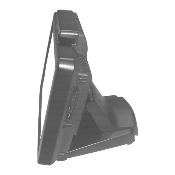
OVERVIEW SCOPE The KS-6810 series is a series of fully integrated PC based Point-Of-Sale terminals. This series provides satisfactory performance for Point-Of-Sale, Hospitality and Kiosk systems with a Intel CPU of ATOM N270 inside an Aluminum alloy die cast enclosure without any exhaust fan, therefore not only provides no noise environment but also supports application in much wider environment conditions. -
Page 7: Optional Items
Preload POSReady, WinXP Pro, Win 7 or Linux. e) Wireless LAN adaptor in USB interface RJ45 to DB9 serial port conversion cable g) MSR with 2 or 3 tracks, USB or PS/2 interface. h) LPT adaptor cable. VGA adaptor cable. KS-6810 series Technical Manual 2... -
Page 8: General Specification
Power OFF to ON duration: 10 seconds min. 12VDC POWER SUPPLY INTO SYSTEM O / P: 12 +/- 1 V DC 4.2 Amp. I / P : 90 VAC/1.2A ~ 240 VAC/0.6A max., 47 ~ 63 Hz KS-6810 series Technical Manual 3... -
Page 9: Overall Power Output Limits
CF CARD READER IN MAIN UNIT Installed in right side of display unit IDE interface Accept Compact Flash memory card Type I PRELOAD OS Option among POSReady, Win XP pro, Win 7, WinCE 6.0 and Linux KS-6810 series Technical Manual 4... -
Page 10: Operator Display
257 mm (W) x 225.7 mm (D) x 178 mm (H) or 10.1” x 8.8” x 7.0” PACKING: 498 mm (W) x 438 mm (D) x 345 mm (H) or 19.6” x 17.2” x 13.6” WEIGHT: 4.1 kg (9.04 lbs)GW4.7kg KS-6810 series Technical Manual 5... -
Page 11: Environmental
26°C (78.8°F) Non-operating: 10%RH ~ 80%RH, non-condensing, max. wet bulb 28.9°C (84.0°F) DB9 / RJ45 conversion cable: 2 pcs COMPLIANCE APPROVALS Whole system meet CE, FCC class A standard (meet IEC61000-4-2/-3/-4/-5/-6/-8/-11) RoHS, WEEE KS-6810 series Technical Manual 6... -
Page 12: Options
15º, 30º, 45º Power source 5 V DC in DB9 or USB Serial(RS-232)/USB Serial(RS-232)/USB Interface DRAM EXPANSION DDR2 400/533 SODIMM in 1 socket up to total 2 GB max. WIRELESS LAN IEEE 802.11b/g in USB interface KS-6810 series Technical Manual 7... -
Page 13: 2.5" Hdd In Base
2.5” HDD IN BASE Ultra SATA II TOP MOUNT MSR To be installed in top side of KS-6810 series main unit USB or PS/2 interface in proprietary internal connector ISO 2 tracks ((track 1 + track 2) or (track 2 + track 3)) -
Page 14: Printer
1. Dot matrix impact 9 pin 2. Bi-directional printing 3. Friction feed type 4. 40 columns for 16.9 CPI 5. Accepts paper width 3 inches (76 mm) 6. Prints on ordinary or up to 3-fold carbonless copy paper KS-6810 series Technical Manual 9... - Page 15 3. High speed thermal line printer up to 220 mm/sec 4. High resolution 8 dots/mm by 512 dots/line (576 dots max.) 5. Epson TM-T88 IV compatible command set 6. Low noise high reliability 7. Auto guillotine type cutter provides single point left partial cut KS-6810 series Technical Manual 10...
- Page 16 11. Supports option spill protect cover 12. Supports option either alarm type or buzzer type kitchen alarm PP-8000L LAN interface All other features same as PP8000 PP-8000U USB interface All other features same as PP8000 KS-6810 series Technical Manual 11...
-
Page 17: Reliability Specification
MSR LIFE EXPECTANCY: 500,000 PASSES POWER SWITCH LIFE EXPECTANCY: 50,000 STROKES WHOLE SYSTEM MTBF: 50,000 HOURS POWER ADAPTOR MTBF: 50,000 HRS LCD PANEL LIFE EXPECTANCY: 20,000 HRS FOR LAMP HDD MTBF: 50,000 HRS EXTERNAL FDD MTBF: 80,000 HRS KS-6810 series Technical Manual 12... -
Page 18: System Definitions
Buttons Manager SSD in HDD in Cash I/O Chip Audio Main unit Base CR Port CF Reader Drawer CODEC COM1 COM2 COM3 Speaker (DB9M) (DB9M) (RJ45) (+5V) (+5V) (+5V) RS232 RS232 RS232 Device Device Device KS-6810 series Technical Manual 13... -
Page 19: 12 V Dc In Connector
This port is utilized by the system in pnp (Plug-N-Play) way, IRQ assigned is not fixed for this port. Most usual observation is IRQ 11. CF CARD READER SLOT This port is a standard CF Type I connector. KS-6810 series Technical Manual 14... -
Page 20: Cash Drawer Connecter
IRQ 4 is assigned to COM1, IRQ 3 is assigned to COM2. Can be changed in CMOS setup. • Power supply selection: please refer to the description in chapter of “POWER SUPPLY TO I/O PORTS”. KS-6810 series Technical Manual 15... -
Page 21: Serial Port Com3
RS232 standard. • IRQ setting for COM3 can be changed in CMOS setup. USB0 / USB1 / USB2 / USB3 PIN ASSIGNMENT OF EACH 4 PIN JACK: PIN # DEFINITION -DATA +DATA PIN 1 KS-6810 series Technical Manual 16... -
Page 22: Sata Connector
PIN ASSIGNMENT OF EACH 7 PIN CONTACTS: PIN # DEFINITION PIN 1 PIN 1 HDD POWER CONNECTOR This connector is a small 4 pin connector with housing PIN ASSIGNMENT OF 4 PIN CONTACTS: PIN # DEFINITION + 5 VDC PIN 1 KS-6810 series Technical Manual 17... -
Page 23: Application Guides
COM PORT APPLICATION COMMENT There are 2 types of connectors for the 3COM ports supported in KS-6810 series. The COM1/2 take standard format of DB9 and are utilized as usual PC COM port. However, the COM 3 are in format of 10 pin RJ45 type modular connector and can operate as regular PC COM port after a separately prepared conversion cable is applied. -
Page 24: Cf Card Issues
LED could indicate power on status while the system remains off. In such case, please use the forced power off function to cancel the error and wait for 10 seconds before switching on again. KS-6810 series Technical Manual 19... -
Page 25: Automatic Power On Control
Windows DOS or Command Prompt Mode. In this application, there needs to be 1 master machine and 1 target machine connected together through LAN. Both machines should be using same brand of LAN chip. KS-6810 series Technical Manual 20... -
Page 26: Posiflex Tools
MAC addresses which of the target machine and press “OK” button then the LAN Wake Up function can be work. POSIFLEX TOOLS In the preinstalled OS there will be a program group named “POSIFLEX Tools” for specific Posiflex device(s) installed. POSIFLEX MSR MANAGER... -
Page 27: Enable Msr Track
A tick in the check box enables the reading of track 3 data if the reader head for track 3 exists. Without this check, the data of track 3 on the MSR will be ignored. KS-6810 series Technical Manual 22... -
Page 28: Msr Will Send The Leading Code
When data read from the MSR is marching to the system, a programmable time delay is inserted between any two characters. The value to define this intercharacter delay ranges from 0 to 32. The correspondent delay time ranges from 2 ms to 66 ms. KS-6810 series Technical Manual 23... - Page 29 These two options provide users to reset all the MSR maneuver functions to the proper defaults according to the system language the user uses. This consideration involves mostly of the Alt-Num emulation and the intercharacter delay. KS-6810 series Technical Manual 24...
-
Page 30: Posiflex Usb Touch Manager
Calibrate – This button engages the “Posiflex USB Touch Calibrator”. Edge Acceleration – This function engages the “Posiflex USB Touch Edge Acceleration Tool” and helps to find the hidden taskbar or thin scroll bar through touch. - Page 31 OK – This button accepts all parameters set and closes the utility window. Apply – This button accepts all parameters set and remains in the utility window. Cancel – This button discards all changes to the parameters and closes the utility window. KS-6810 series Technical Manual 26...
- Page 32 However, the next touch will resume the left button of mouse unless the small window is touched again. KS-6810 series Technical Manual 27...
-
Page 33: Hardware Details
HARDWARE DETAILS MAIN BOARD (KS-6810) COMPONENT SIDE MSR1 LED1 LVDS1 SATA PWR2 SATA2 PWR1 BAT1 TOUCH1 USB1 JP10 LAN1 SPK1 COM3 USB2 USB3 SATA COM1 COM2 SATA KS-6810 series Technical Manual 28... -
Page 34: Solder Side
SOLDER SIDE U7G1 LPT1 CL_CMOS VGA2 KS-6810 series Technical Manual 29... -
Page 35: Jumpers And Connectors
Usage CL_CMOS HDR 1x3 CMOS data control HDR 2x4 Touch Panel OS Support Setting. HDR 1x3 USB Touch Speaker Volume Setting. HDR 2x10 w/H Parallel port cable connector U7G1 Micro FCBGA IC NB chip (CN700) KS-6810 series Technical Manual 30... -
Page 36: Jumper Settings
3 – 4 short FIJISTU Touch Panel 3 – 4 open ELO Touch Panel 5 – 6 short Windows /Linux / Win CE 5 – 6 open MS - DOS 7 – 8 short Reserved KS-6810 series Technical Manual 31... - Page 37 Disable EUP support but support LAN/Alarm/modem wake up & power fail after power on function. Reserved for RD debug CMOS DATA CONTROL STATUS OF ON SOLDER SIDE 1– 2 short Disable 2– 3 open Debug. KS-6810 series Technical Manual 32...
-
Page 38: Usb Msr Control Board (Sd320)
Alt + Num Num Lock Class Function When Open Enabled Enabled Vendor When Short Disabled Disabled Windows Note: The Enable/Disable for each Track and Leading/Ending Code can only be set through use of USB MSR Manager. KS-6810 series Technical Manual 33... -
Page 39: Ps/2 Msr Control Board (Sd420)
Dual Color LED Deleted JUMPER SETTING Jumper Function Card Type Alt + Num Leading Code Track 1 Track 2 Track 3 When Open ISO Enabled Enabled Disabled Disabled Disabled When Short JIS Disabled Disabled Enabled Enabled Enabled KS-6810 series Technical Manual 34... -
Page 40: Service And Spare Parts
OPEN BASE BACKCOVER Open the back cover of base by releasing the hooks of back cover as described in the User’s Manual. KS-6810 series Technical Manual 35... -
Page 41: Service Window
HDD fixing screws without turning them tight. Connect the HDD power cable and the SATA end of HDD cable to the system. Apply a new cable tie to hold these cables at the left holder slit. KS-6810 series Technical Manual 36... -
Page 42: Replace Hinge
MSR; LED; LCD panel; inverter. Please note that in the example picture the cable for optional MSR is not installed. For later reinstallation, please first insert the bottom edge of the system back cover into KS-6810 series Technical Manual 37... -
Page 43: Top Mount Upgrade Kit
MSR reader head (a dummy MSR if no MSR installed) MSR fixing screw MSR control board (SD-300D for USB interface or SD-420A for PS/2 interface) MSR control fixing screw Cable from MSR reader head Cable to main board Grounding wire RELEASE FRONT BEZEL KS-6810 series Technical Manual 38... -
Page 44: Replace Lcd &Touch Panel
After release the front bezel, please separate the bracket and touch panel & LCD panel assembly. Please pay particular attention when attach the touch panel & LCD panel assembly back to the bracket before they are reassembled. KS-6810 series Technical Manual 39... -
Page 45: Replace Mainboard
B: Afterward, take the SSD HDD with fixed bracket to the location where is on the back of LCD bracket and push the module as blue circled and arrowed in the following picture. C: After fasten the module; please plug the power and data cable to the SSD HDD module. KS-6810 series Technical Manual 40... -
Page 46: Spare Parts List
10.4" LCD Adapter Board Assembly, w/ Double Side 35464016000 Tapes & Gasket 16550108020 LCD Holder for 10.4" LCD 21862041030 Ground Wire, L=65mm 10684038062 Binding Head Screw #6-32NC-6L 49802602100 PS/2 ISO Magnetic Strip Reader Control Board, Ver.0 KS-6810 series Technical Manual 41... - Page 47 21943003202 1" SATA Disk Moudle 32G 36556003003 Base Stand Assembly for KS-2010/KS-6810, Black 36556003006 Base Stand Assembly for KS-2010/KS-6810, Ivory 10684038123 Binding Head Screw #6/32-12L SW+W-NiB 16550304013 Plastic Neck Cover, Black 16550304016 Plastic Neck Cover, Ivory KS-6810 series Technical Manual 42...
- Page 48 36594018000 Connector Plate, M/B Ver.B1 10161414005 Silicon Rubber 14*14*0.5 mm 16550307017 Power Button, Blue 10684038103 Binding Head Screw #6/32-10L 10684038082 Bind Head Screw,#6/32-8L SW+W-Ni 21863061621 LVDS Cable for KS-6810, L=200mm 21865033022 Power LED Cable Blue/Yellow KS-6810 series Technical Manual 43...
- Page 49 21868801300 Power Cord for India,3 Wire,IEC 320-C13 Power Cord for Argentina,3 Wire, L=1800mm, 21868901300 IEC320-C13 16550510120 Carton for KS-2010/6810 PE Bag 49 *55 CM 16550540010 PE Foam 16590905020 Manual for KS-6810 21862062300 VGA Cable, L=130mm 21862033420 Parallel Conversion Cable, L=400mm KS-6810 series Technical Manual 44...
-
Page 50: Assembly Drawing
ASSEMBLY DRAWING Opt. KS-6810 series Technical Manual 45...
Need help?
Do you have a question about the KS-6810 SERIES and is the answer not in the manual?
Questions and answers