Table of Contents
Advertisement
Quick Links
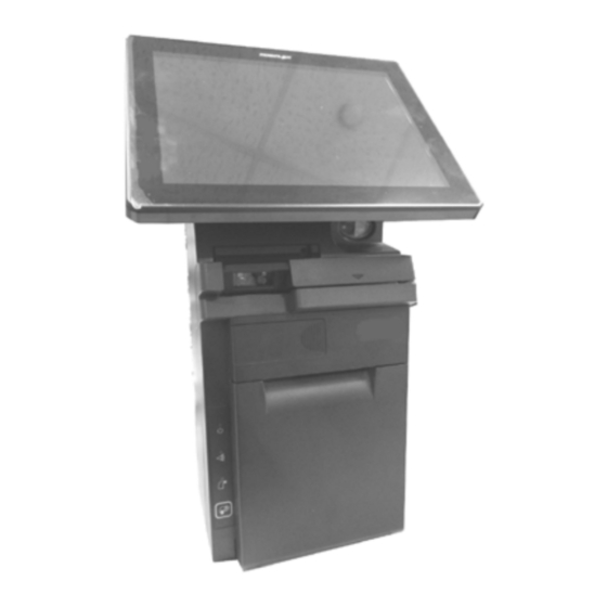
HS-6510W/6512W/6514W
JIVA Desktop POS
User Manual
Package Contents
15680900010 Ver. A0
http://www.posiflex.com
HS-6510W/6512W/6514W desktop POS (x 1)
24V/100W Power Adaptor (x 1)
Power cord (x 1)
3-inch wide thermal paper roll (x 1)
Paper separator for 2" thermal paper roll (x 1)
Desktop mounting kit pack for HS-6510/6512 (x 1)
(including 1 desktop mounting bracket,
4 fixing screws, and 4 plastic anchors)
Desktop mounting kit pack for HS-6514 (x 1)
(including 1 bottom plate, 1 desktop mounting
bracket, 4 fixing screws, and 4 plastic anchors)
User manual (x 1)
1
Advertisement
Table of Contents

Subscribe to Our Youtube Channel
Related Manuals for POSIFLEX HS-6510W


Summary of Contents for POSIFLEX HS-6510W
- Page 1 HS-6510W/6512W/6514W JIVA Desktop POS User Manual Package Contents HS-6510W/6512W/6514W desktop POS (x 1) 24V/100W Power Adaptor (x 1) Power cord (x 1) 3-inch wide thermal paper roll (x 1) Paper separator for 2” thermal paper roll (x 1) ...
- Page 2 Views of HS-6510W/6512W/6514W Front View HS-6510W/6512W/6514W P-CAP Touch & LCD Panel Fingerprint or iButton Sensors (Optional) Posiflex 2D Scanner (Optional) 3-Track Magnetic Paper Jam Rescue Stripe Reader Compartment (Optional) Power LED Indicator Printer Error Printed Paper Exit LED Indicator Printer Paper-Out...
- Page 3 Left Side View Power Button Right Side View RFID Card Reader (Optional) Paper Roll Cover Release Lever...
- Page 4 Bottom View Rubber Pad Rubber Pad Bottom I/O Interface Mounting holes Views of I/O Interface of HS-6510W/6512W/6514W Top I/O Interface USB 2.0 Port VGA Port RJ-50 COM Port DB-25 Parallel Port Bottom I/O Interface 24V DC-IN Power Jack Line Out...
-
Page 5: Connecting Power Adapter
Connecting Power Adapter Please refer to the following instructions on how to connect power adapter to HS-6510W/6512W/6514W and to organize your cables. Lay your desktop POS on a level surface with its touch screen facing down as shown in the figure. - Page 6 Loading 2” or 3” Paper Rolls Before operating the printer, please follow the below steps to load a paper roll. To open the paper roll cover, push down the paper roll cover release lever in the direction shown in the figure. Before installing 2-inch paper roll in the thermal printer, place paper separator in the paper roll compartment by following the instructions below.
- Page 7 To load the thermal printer with the 3-inch paper roll, just drop the thermal paper roll inside the paper roll compartment of the printer as illustrated in the figure. Unroll the thermal paper and drag the loose end of the paper till it extends towards the paper cutter.
-
Page 8: Troubleshooting Paper Jams
Troubleshooting Paper Jams When it comes to the common printing problems, it is inevitable that you might encounter the issue of paper jams at some point. The following steps are provided to assist you in fixing the problem. Before proceeding, make sure that your POS terminal is properly shut down. - Page 9 Replacing POS Receipt Printer Module HS-6510W/6512W/6514W offers a quick solution to help you to replace POS receipt printer module when there is a need. Please go through the steps described below to achieve the purpose. Before proceeding the procedure, please ensure that the terminal is completely shut down.
- Page 10 Disconnect all the cables indicated in the figure. Take the new printer module which you wish to replace with, and then connect the cables to the printer control board as indicated in the following figures. Connect the CR cable to CR port on the control board.
- Page 11 After ensuring the front cover is well attached to the rear case, insert the two screws back into the screw holes inside the compartment, secure them, and then close the cover. Insert the screw which you removed in step 1 to the screw hole at the bottom, and then fasten it properly, as the figure shows.
- Page 12 Push the POS backwards along the rail slots of the bracket until the terminal is locked into place. After inserting another two scerws into the two mouting holes located on the rear of the POS, fasten them to fix the POS termial to the bottom plate.
- Page 13 After placing the mounting bracket in your preferred mounting position, use the screw holes of the mounting bracket to drill two holes on the surface. Each hole has to be at least ” or 6.25 mm diameter and ” or 35mm in depth.
- Page 14 To completely mount the desktop POS onto the table, please follow the steps below. Use the two mouting holes located on the rear of the POS to drill another two holes on the same surface. Each hole also has to be at least ”...
-
Page 15: Installing An Operating System
Installing a Customer Display to HS-6510W/6512W/6514W HS-6510W/6512W/6514W also allows you to additionally install a customer display to expand its functionality. Based on the model of the second display, the step-by-step instructions are provided in its own user guide to help you mount it onto your POS system. - Page 16 10 seconds. Operating the Magnetic Stripe Reader (Optional) To have the magnetic stripe reader of HS-6510W/6512W/6514W work properly, you must bear in mind the following tips while swiping your MSR cards through the reader.
- Page 17 RFID reader as shown below. Scanning Barcodes with Posilfex 2D Scanner (Optional) The integrated Posiflex 2D Scanner is another prominent feature of HS- 6510W/6512W/6514W. With its hand-free design, it offers a more convenient solution for users to read 1D/2D barcodes and then transmitted scanned data to the terminal for further processing, which greatly increases your working efficiency.
-
Page 18: Status Led Indicator
Fingerprint Sensor iButton Sensor Status LED Indicator After HS-6510W/6512W/6514W is powered on, it is significant to observe the status of LED indicators anytime to ensure your system functions normally. More importantly, knowing how to interpret the status indicators enables you to perform basic troubleshooting more efficiently. -
Page 19: Specifications
1 x RJ50 Port (on the top I/O plate) Parallel Port CR Port 1 Port controlling 2 CR D-SUB 15-pin , with 12V power for Posiflex LCD VGA Port monitors 4 x USB 2.0 ports (one on the top I/O plate and the other... - Page 20 5, POSTNET, MSI/Plessey, UK/Plessey, Code 128,GS1- Symbology Databar, GS1-Databar Limited, GS1-Databar Expanded, QR Code, PDF417 The product information and specifications are subject to change without ※ prior notice. To get the detailed information on the HS- 6510W/6512W/6514W, please check this model from Posiflex Global Website...
Need help?
Do you have a question about the HS-6510W and is the answer not in the manual?
Questions and answers