Table of Contents
Advertisement
Quick Links
Advertisement
Table of Contents

Related Manuals for Bayliner 305


Summary of Contents for Bayliner 305
-
Page 3: Hull Identification Number
This document discloses subject matter in which Bayliner has proprietary rights. The information and design disclosed herein were originated by and are the prop- erty of Bayliner. Neither receipt nor possession thereof confers or transfers any right to reproduce, copy, alter or disclose the document or any part thereof, any information contained therein, or to construct boats or any item from it, except by written permission from or written agreement with Bayliner. -
Page 4: Table Of Contents
CONTENTS Chapter 1: Welcome Aboard! Chapter 3: Propulsion & Related Systems Dimensions & Tank Capacities Engines Layout View Bilge Blower System Dealer Service Fuel System Warranty Information Boating Experience 28 Fuel Fill & Vent 28 Gas Engine Fuel Filters Engine & Accessory Guidelines 29 Fuel Filter/Water Separators (Diesel 3 Engine &... - Page 5 Chapter 6: Plumbing Chapter 10: Lights Bilge Pumps Care & Maintenance 39 Bilge Pump Testing Interior & Exterior Lights 40 Autofloat Switches Navigation Lights Seawater Systems Spotlight (If Equipped) 41 Seacocks 41 Seawater Strainers Freshwater System Chapter 11: Heating & Air Conditioning 42 Transom Shower (If Equipped) Air Conditioning System (If Equipped) 43 Freshwater System Winterization...
- Page 6 Hazard Boxes & Symbols The hazard boxes and symbols shown below are used throughout this supplement to call attention to potentially dan- gerous situations which could lead to either personal injury or product damage. Read all warnings carefully and fol- low all safety instructions.
-
Page 7: Chapter 1: Welcome Aboard
• Contact your dealer if you have any problems with your new boat. • If your dealer cannot help, call our customer service hotline: 360-435-8957 or send us a FAX: 360-403-4235. • Buy replacement parts from any authorized Bayliner dealer. -
Page 8: Warranty Information
• Bayliner offers a Limited Warranty on each new Bayliner purchased through an authorized Bayliner dealer. • A copy of the Limited Warranty was included in your owner’s packet. • If you did not receive a copy of the Limited Warranty, please contact your Bayliner dealer or call 360-435-8957 for a copy. -
Page 9: Engine & Accessory Literature
Refer to the engine manual for engine RPM ratings. The engines should reach, but not exceed their full rated RPM when full-throttle is applied. Immediately contact your local Bayliner dealer if: • The engines cannot reach their full rated RPM when full-throttle is applied, or;... -
Page 10: Safety Standards
Chapter 1: Welcome Aboard! 305 • Owner’s Manual Supplement Safety Standards DANGER! FALLING and ROTATING PROPELLER HAZARD! • NEVER allow anyone to ride on parts of the boat NOT designed for such use. • Sitting on seat backs, lounging on the forward deck, bow riding, gun- wale riding or occupying the transom platform while underway is especially hazardous and WILL cause personal injury or death. -
Page 11: Special Care For Moored Boats
305 • Owner’s Manual Supplement Chapter 1: Welcome Aboard! Special Care For Moored Boats NOTICE • To help seal the hull bottom and reduce the possibility of gelcoat blistering on moored boats, apply an epoxy barrier coating. The barrier coating should be covered with several coats of anti-fouling paint. -
Page 12: Boat Lifting
Chapter 1: Welcome Aboard! 305 • Owner’s Manual Supplement Boat Lifting WARNING! PERSONAL INJURY and/or PRODUCT OR PROPERTY DAMAGE HAZARD! • Lifting slings may slip on the hull. • Avoid serious injury or death by securing the lifting slings together BEFORE lifting. -
Page 13: Carbon Monoxide (Co)
305 • Owner’s Manual Supplement Chapter 1: Welcome Aboard! Carbon Monoxide (CO) DANGER! • Carbon monoxide gas (CO) is colorless, odorless, tasteless, and extremely dangerous. • All engines, generators, and fuel burning appliances produce CO as exhaust. • Prolonged exposure to low concentrations or very quick exposure to high concentrations WILL cause BRAIN DAMAGE or DEATH. -
Page 14: Where And How Co Can Accumulate
Chapter 1: Welcome Aboard! 305 • Owner’s Manual Supplement Where and How CO Can Accumulate Stationary Conditions That Increase CO Accumulations Include: A. Using engine, generator, or other fuel burn- B. Mooring too close to another boat that is ing device when boat is moored in a con- using its engine, generator, or other fuel fined space. -
Page 15: Co Checklists
305 • Owner’s Manual Supplement Chapter 1: Welcome Aboard! CO Checklists Trip Checklist Make sure you know where the exhaust outlets are located on your boat. Educate all passengers about the symptoms of CO poisoning and where CO may accumulate. -
Page 16: More Information
Chapter 1: Welcome Aboard! 305 • Owner’s Manual Supplement More Information For more information about how you can prevent carbon monoxide poisoning on recreational boats and other ways to boat more safely, contact: United States Coast Guard National Marine Manufacturers American Boat &... -
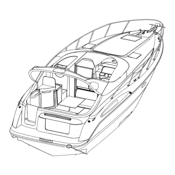
Page 17: Chapter 2: Locations
305 • Owner’s Manual Supplement Chapter 2: Locations Exterior Views Hull Views PORTLIGHTS (TYPICAL) AFT BILGE FUEL TANK WATER TANK VENT VENT PUMP DRAIN STARBOARD HULLSIDE COCKPIT ICE TUB ROPE LOCKER DRAIN DRAIN DRAIN AIR CONDITIONER HEAD SINK SHOWER WASTE TANK... -
Page 18: Forward Deck View
Chapter 2: Locations 305 • Owner’s Manual Supplement Forward Deck View WIPERS VENTILATION HATCHES CLEAT BOW HATCH ROPER LOCKER HATCH WINDLASS & DECK SWITCHES (IF EQUIPPED) CLEAT SPOTLIGHT (IF EQUIPPED) NAVIGATION LIGHT CLEAT ANCHOR NAVIGATION CLEAT ROLLER LIGHT Aft Deck View... -
Page 19: Helm Station
305 • Owner’s Manual Supplement Chapter 2: Locations Helm Station NOTE: TYPICAL HELM LAYOUT SHOWN. ACTUAL LAYOUT MAY VARY DEPENDING ON ENGINE AND ACCESSORY OPTIONS. TACHOMETER DEPTH GAUGE VOLT GAUGE SPEEDOMETER TACHOMETER FUEL GAUGE TEMPERATURE GAUGE OIL GAUGE TRIM GAUGES... -
Page 20: Component Locations
Chapter 2: Locations 305 • Owner’s Manual Supplement Component Locations 12-Volt Accessory Outlets: • One is located inside the helm storage tub. 12-VOLT OUTLET • One is located inside the forward upper galley cabinet. 12-VOLT OUTLET 12-Volt DC Fuses: Located on... - Page 21 305 • Owner’s Manual Supplement Chapter 2: Locations 110-Volt AC Master Electrical Panel: Located on the aft wall of the galley. 110-VOLT AC PANEL Air Conditioner Intake Pump (If Equipped): AIR CONDITIONER INTAKE PUMP • Located in the utility room.
- Page 22 Chapter 2: Locations 305 • Owner’s Manual Supplement Air Conditioner Unit (If Equipped): • Located under the v-berth mattress. • Access is through the center v-berth hatch. CENTER V-BERTH HATCH Batteries: Located in the starboard forward area of the engine room.
- Page 23 305 • Owner’s Manual Supplement Chapter 2: Locations Battery Switch Panel: Located COCKPIT inside the cockpit entertainment ENTERTAINMENT center cabinet. CENTER BATTERY SWITCHES Bilge Pump & Float Switch - Aft: Located next to the transom wall in the center of the engine room bilge.
- Page 24 Chapter 2: Locations 305 • Owner’s Manual Supplement CO Monitor: Located on the starboard aft wall in the dinette area. CO MONITOR Depth Sounder Thru-hull Transducer: Located in the engine room, forward of the star- board engine. STARBOARD ENGINE TRANSDUCER Freshwater Fill Deck Fitting: Located on the starboard deck.
- Page 25 305 • Owner’s Manual Supplement Chapter 2: Locations Freshwater Pump: • Located in the utility room. FRESHWATER PUMP • Access is through the wall hatch on the port side of the aft berth. UTILITY ROOM Freshwater Pump Switch: Located in the galley.
- Page 26 Chapter 2: Locations 305 • Owner’s Manual Supplement Freshwater Tank: • Located in the bilge area under the entry steps. FRESHWATER TANK • Access by lifting up the top step. Fuel Fill Deck Fitting: Located on the star- board aft corner of the deck.
- Page 27 305 • Owner’s Manual Supplement Chapter 2: Locations Fuel Tank: • Located in the bilge under the aft-berth. • Access to the fuel tank fittings is in the FUEL TANK forward area of the engine room. GAS GENERATOR INTAKE SEACOCK Generator (If Equipped): Located in the center of the engine room.
- Page 28 Chapter 2: Locations 305 • Owner’s Manual Supplement Macerator & Macerator Discharge Sea- cock (If Equipped): Located on the transom wall in the aft area of the engine room. MACERATOR DISCHARGE SEACOCK Marine Head Seawater Intake Seacock: Located in the engine room, forward of the port engine.
- Page 29 305 • Owner’s Manual Supplement Chapter 2: Locations Shower Drain Pump: • Located in the bilge area under the entry stairs. SHOWER DRAIN PUMP • Access by lifting up the top step. Shower Drain Pump Switch: Located on the head vanity.
- Page 30 Chapter 2: Locations 305 • Owner’s Manual Supplement Spotlight Control Panel: Located at the helm, near the shift/throttle levers. SPOTLIGHT CONTROL PANEL (IF EQUIPPED) Trim & Tilt Pumps & Reservoirs: Located on the transom wall in the center of the engine room.
- Page 31 305 • Owner’s Manual Supplement Chapter 2: Locations Waste Pump-out Deck Fitting: Located on the port aft deck, next to the transom door. WASTE PUMP-OUT DECK FITTING Water Heater: • Located in the utility room. • Access is through the wall hatch on the port side of the aft berth.
-
Page 32: Chapter 3: Propulsion & Related Systems
305 • Owner’s Manual Supplement Chapter 3: Propulsion & Related Systems Engines Read the engine operation and maintenance manuals before starting or working on the engines. Bilge Blower System WARNING! FIRE/EXPLOSION HAZARD • Use of the bilge blower system is NOT A GUARANTEE that explosive fumes have been removed. -
Page 33: Fuel System
305 • Owner’s Manual Supplement Chapter 3: Propulsion & Related Systems Fuel System WARNING! FIRE, EXPLOSION AND OPEN FLAME HAZARD! • It is very important that the fuel system be inspected thoroughly the first time it is filled and at each subsequent filling. -
Page 34: Fuel Fill & Vent
Chapter 3: Propulsion & Related Systems 305 • Owner’s Manual Supplement DIESEL ENGINE FUEL SYSTEMS (IF EQUIPPED) FUEL FILTER/ WATER SEPARATORS FUEL SHUT- OFF VALVES FUEL TANK VENT HOSE FUEL FILL HOSE FUEL TANK FUEL RETURN LINES FUEL LINES TO ENGINES Fuel Fill &... -
Page 35: Fuel Filter/Water Separators (Diesel Engines Only)
305 • Owner’s Manual Supplement Chapter 3: Propulsion & Related Systems Fuel Filter/Water Separators (Diesel Engines Only) NOTICE • The frequency of water draining or element replacement is determined by the contamina- tion level in the fuel. • Inspect the collection bowls for water daily. -
Page 36: Fire Suppression System (If Equipped)
Chapter 3: Propulsion & Related Systems 305 • Owner’s Manual Supplement Fire Suppression System (If Equipped) • The fire suppression system is designed to extinguish engine compartment fires. MANUAL • Before using your boat for the DISCHARGE T-HANDLE first time, read the fire suppres- sion system’s instruction and... -
Page 37: Quick Oil Drain System
305 • Owner’s Manual Supplement Chapter 3: Propulsion & Related Systems Quick Oil Drain System • A quick oil drain assembly is attached to the oil pan on each engine. • Some setup is needed before you can use this system. - Page 38 Chapter 3: Propulsion & Related Systems 305 • Owner’s Manual Supplement 3. Unclip the bilge plug swivel clip from the cable on the end of BILGE PLUG the oil drain hose. NOTE: This bilge OIL DRAIN plug assembly will SWIVEL CLIP HOSE CABLE be your spare.
-
Page 39: Using The Quick Oil Drain System
305 • Owner’s Manual Supplement Chapter 3: Propulsion & Related Systems • At this point, both of the oil drain hose cables should be hanging out of the bilge drain. OIL DRAIN HOSE CABLES 9. Clip the bilge plug swivel clip to both of the oil drain hose cables. -
Page 40: Chapter 4: Controls & Gauges
305 • Owner’s Manual Supplement Chapter 4: Controls & Gauges Steering • This boat features a power assisted rack-and-pinion steering system. • For information about the ‘power assist fluid reservoir’, refer to the engine operation and maintenance manual. • Boat steering is not self-centering. -
Page 41: Trim Tabs
305 • Owner’s Manual Supplement Chapter 4: Controls & Gauges Trim Tabs WARNING! LOSS OF CONTROL HAZARD! Improper use of trim tabs WILL cause loss of control! • Do NOT allow anyone unfamiliar with trim tabs to use them. • Do NOT use trim tabs in a following sea as they WILL cause broaching or other unsafe han- dling characteristics. -
Page 42: Gauges
Chapter 4: Controls & Gauges 305 • Owner’s Manual Supplement Gauges Cleaning Gauges CAUTION PRODUCT or PROPERTY DAMAGE HAZARD! • Use only mild soap and water to clean the gauge lenses and bezels. • Use of other cleaners, including common window cleaning solutions, may cause the lenses to crack. -
Page 43: Chapter 5: Navigation & Communication Equipment
305 • Owner’s Manual Supplement Chapter 5: Navigation & Communication Equipment Read the manuals for all navigation & communication equipment before using these systems. Compass NOTICE • Compass accuracy can be affected by many factors. • Have a qualified technician calibrate your compass. -
Page 44: Chapter 6: Plumbing
305 • Owner’s Manual Supplement Chapter 6: Plumbing Bilge Pumps NOTICE Discharge of oil, oil waste, or fuel into navigable waters is prohibited by law. Violators are sub- ject to legal action by the local authorities. • Your boat is... -
Page 45: Bilge Pump Testing
305 • Owner’s Manual Supplement Chapter 6: Plumbing Bilge Pump Testing • The bilge pumps are vital to the safety of your boat. • Test the bilge pumps often to make sure they are working properly. To test each bilge pump: 1. -
Page 46: Autofloat Switches
Chapter 6: Plumbing 305 • Owner’s Manual Supplement Autofloat Switches • The automatic bilge pumps use float (autofloat) switches to automatically turn On the pumps whenever water rises to a preset level in the bilge. • The autofloat switches are normally mounted next to the bilge pumps they control. -
Page 47: Seawater Systems
305 • Owner’s Manual Supplement Chapter 6: Plumbing Seawater Systems Seacocks WARNING! FLOODING & SWAMPING HAZARD! • Close the seacock(s) when leaving the boat unattended for any length of time. • If a seacock is left open, a hose failure could flood the bilge, swamp the batteries and the engines, and even sink the boat. -
Page 48: Freshwater System
Chapter 6: Plumbing 305 • Owner’s Manual Supplement Freshwater System WARNING! • Only use safe drinking (potable) water in your boat’s freshwater system. • Only use an FDA approved, white 'drinking water safe' hose to fill the freshwater tank. • NEVER use a common garden hose for drinking water. -
Page 49: Freshwater System Winterization
305 • Owner’s Manual Supplement Chapter 6: Plumbing Freshwater System Winterization CAUTION WATER SYSTEM DAMAGE HAZARD! NEVER blow compressed air through the water system when all of the faucets are Closed. 1. Turn Off the water heater breaker switch. NOTE: Tag or Mark the water heater breaker switch to prevent it from being turned On while the water heater tank is empty. -
Page 50: Water Heater
Chapter 6: Plumbing 305 • Owner’s Manual Supplement Water Heater WARNING! SCALDING HAZARD! Water heated by the water heater can be hot enough to scald the skin. CAUTION WATER HEATER DAMAGE HAZARD! • Do NOT turn On the water heater electrical circuit on the 110-volt AC master panel until the water heater tank is COMPLETELY filled with water. -
Page 51: Drain Systems
305 • Owner’s Manual Supplement Chapter 6: Plumbing Drain Systems Deck Drains • Water on the deck is drained overboard through the deck drains. • Keep the deck drains free of debris. Gray Water Drains The sinks are above the waterline and are gravity drained overboard. -
Page 52: Marine Head With Holding Tank
Chapter 6: Plumbing 305 • Owner’s Manual Supplement Marine Head with Holding Tank NOTICE Check with local authorities for regulations regarding the legal use of marine head systems. • Before using this system, read the marine head operation and mainte- nance manual. -
Page 53: Winterizing The Marine Head
305 • Owner’s Manual Supplement Chapter 6: Plumbing Winterizing the Marine Head Read the marine head operation and maintenance manual for winterizing instructions. Macerator (If Equipped) NOTICE Check with local authorities for regulations regarding the legal use of marine head systems. -
Page 54: Chapter 7: Deck Equipment
305 • Owner’s Manual Supplement Chapter 7: Deck Equipment Cleats & Tow Eyes WARNING! PERSONAL INJURY and/or77 PRODUCT or PROPERTY DAMAGE HAZARD! NEVER lift the boat using the bow and stern eyes or the cleats. Read the section on towing in the Cruiser & Yacht Owner’s Manual before: •... -
Page 55: Canvas
305 • Owner’s Manual Supplement Chapter 7: Deck Equipment Canvas CAUTION PRODUCT or PROPERTY DAMAGE HAZARD! Take down and securely stow ALL canvas BEFORE transporting your boat by road. NOTICE Two people are needed for most of the tasks listed in this section. -
Page 56: Canvas Care
Chapter 7: Deck Equipment 305 • Owner’s Manual Supplement Canvas Care (see also ‘Clear Vinyl Care’ on next page) • After each use, especially in saltwater, rinse the canvas with cold freshwater. • Before stowing, let the canvas air-dry completely. -
Page 57: Clear Vinyl Care
305 • Owner’s Manual Supplement Chapter 7: Deck Equipment Clear Vinyl Care CAUTION • NEVER store the clear vinyl pieces wet, as this will cause a milky film to develop. • NEVER fold or crease the clear vinyl pieces as cracking will occur. -
Page 58: Chapter 8: Appliances & Entertainment Systems
305 • Owner’s Manual Supplement Chapter 8: Appliances & Entertainment Systems NOTICE Always keep an approved ABC-type fire extinguisher in galley area. • The separate instruction sheets or manuals for all appliances and entertainment systems contain detailed instruc- tions and important safeguards. -
Page 59: Refrigerator
305 • Owner’s Manual Supplement Chapter 8: Appliances & Entertainment Systems Refrigerator The refrigerator runs on 12-volt DC power unless 110-volt AC power is being supplied by shore power or generator power and the refrigerator’s AC breaker is On. Audio Equipment NOTICE AM radio reception may be impaired anytime the engine is running. -
Page 60: Chapter 9: Convertible Seats, Beds, & Tables
305 • Owner’s Manual Supplement Chapter 9: Convertible Seats, Beds, & Tables Dinette to Mid Berth Conversion 1. Remove the table (A) and the table leg (B). 2. Place the filler board (C) so that it fits securely into the recessed edge (D) at the front of the dinette seats. -
Page 61: Cockpit Table To Sunlounge Conversion
305 • Owner’s Manual Supplement Chapter 9: Convertible Seats, Beds, & Tables Cockpit Table to Sunlounge Conversion 1. Lift the table (A) and remove the table leg (B). 2. Put the cross supports (C) in place. 3. Place the table (A) on top of the supports (C). -
Page 62: Chapter 10: Lights
305 • Owner’s Manual Supplement Chapter 10: Lights Care & Maintenance All of the lights installed on your boat are of top quality, but you should be aware that failure may periodically occur for a variety of reasons: 1. There may be a blown fuse - replace the fuse. -
Page 63: Chapter 11: Heating & Air Conditioning
305 • Owner’s Manual Supplement Chapter 11: Heating & Air Conditioning Air Conditioning System (If Equipped) DANGER! CARBON MONOXIDE POISONING HAZARD! Dangerous carbon monoxide gas (CO) can be brought into the boat through the air conditioning system. CAUTION SYSTEM DAMAGE HAZARD! The air conditioning system’s seawater intake seacock MUST be Opened BEFORE turning On... -
Page 64: Chapter 12: Electrical System
305 • Owner’s Manual Supplement Chapter 12: Electrical System DANGER! EXTREME FIRE, SHOCK & EXPLOSION HAZARD! • To minimize the risks of fire and explosion, NEVER install knife switches or other arcing devices in the fuel compartment. • NEVER substitute automotive parts for marine parts. Electrical, ignition and fuel system parts were designed and manufactured to comply with rules and regulations that minimize risks of fire and explosion. -
Page 65: 12-Volt Dc System
305 • Owner’s Manual Supplement Chapter 12: Electrical System 12-Volt DC System Batteries The batteries supply electricity for lights, 12-volt accessories, and engine and generator starting. The Electrical section of Chapter 8, in the Cruiser & Yacht Owner’s Manual, provides battery care and maintenance instructions. -
Page 66: Battery Switch Positions
Chapter 12: Electrical System 305 • Owner’s Manual Supplement Battery Switch Positions NOTICE Since your boat’s batteries were installed by your dealer, the battery switch positions listed below may vary. Make sure your selling dealer fully explains how to use the battery switches. -
Page 67: Alternators
305 • Owner’s Manual Supplement Chapter 12: Electrical System Alternators The alternators will keep the batteries properly charged when the engines are running at, or above, cruising speeds. Battery Charger (If Equipped) CAUTION ENGINE & ELECTRICAL SYSTEM DAMAGE HAZARD! NEVER run the boat’s engines and the battery charger at the same time. -
Page 68: 110-Volt Ac System
Chapter 12: Electrical System 305 • Owner’s Manual Supplement 110-Volt AC System CAUTION WATER HEATER DAMAGE HAZARD! • Do NOT turn On the water heater circuit breaker on the 110-volt AC master panel until the water heater tank is COMPLETELY filled with water. -
Page 69: Shore Power
305 • Owner’s Manual Supplement Chapter 12: Electrical System Shore Power DANGER! FIRE, EXPLOSION & SHOCK HAZARD! • Do NOT alter the shore power connectors and use ONLY compatible connectors. • Turn Off ALL breakers and switches on the 110-volt AC master panel BEFORE plugging in or unplugging the shore power cord. -
Page 70: Connecting To Shore Power
Chapter 12: Electrical System 305 • Owner’s Manual Supplement • The single shore power 110-volt/60-hertz AC system features one 110-volt/30-amp shore power receptacle. • If your boat has an air conditioning system, a second (dual) 110-volt/30-amp inlet has been installed. -
Page 71: Generator (If Equipped)
305 • Owner’s Manual Supplement Chapter 12: Electrical System Generator (If Equipped) DANGER! CARBON MONOXIDE POISONING HAZARD! Generators are a source of dangerous carbon monoxide gas (CO). Check the generator exhaust system for leaks BEFORE each use. WARNING! FIRE/EXPLOSION HAZARD! •... -
Page 72: Electrical Routings
Chapter 12: Electrical System 305 • Owner’s Manual Supplement Electrical Routings 110-Volt AC Hull Harnesses AIR CONDITIONER UNIT DINETTE OUTLET GALLEY OUTLET REFRIGERATOR AC PANEL AFT BERTH OUTLET HEAD OUTLET AIR CONDITIONER BOX BATTERY CHARGER AIR CONDITIONER PUMP WATER HEATER... -
Page 73: 12-Volt Dc Hull Harnesses
305 • Owner’s Manual Supplement Chapter 12: Electrical System 12-Volt DC Hull Harnesses AIR CONDITIONER SUMP PUMP BOX FRESHWATER PUMP SWITCH REFRIGERATOR BILGE PUMP STEREO TO DEPTH FINDER IN DASH HEAD SWITCHES CO MONITOR FRESHWATER PUMP DC PANEL SHOWER PUMP... -
Page 74: 12-Volt Dc Deck Harnesses
Chapter 12: Electrical System 305 • Owner’s Manual Supplement 12-Volt DC Deck Harnesses NOTE: VIEWS ARE UNDERSIDE OF DECK COURTESY OVERHEAD LIGHT LIGHT RADARWING/ HORN COURTESY COURTESY LIGHT LIGHT DASH HEAD OVERHEAD LIGHT STEREO OVERHEAD COURTESY LIGHTS LIGHT SPEAKER NAVIGATION... -
Page 75: Radar Wing Harness
305 • Owner’s Manual Supplement Chapter 12: Electrical System Radar Wing Harness COURTESY LIGHT ALL-ROUND LIGHT COURTESY LIGHT HORN STARBOARD SPEAKER PORT SPEAKER HARNESS PLUG... -
Page 76: Gas Engines Battery Cable System
Chapter 12: Electrical System 305 • Owner’s Manual Supplement Gas Engines Battery Cable System NOTES: POSITIVE BATTERY CABLES ARE RED NEGATIVE BATTERY CABLES ARE YELLOW POSITIVE BATTERY CABLE ROUTING BATTERY SWITCHES PORT ENGINE BATTERY CHARGER GENERATOR (IF EQUIPPED) STARBOARD DC PANEL... -
Page 77: Diesel Engines Battery Cable System
305 • Owner’s Manual Supplement Chapter 12: Electrical System Diesel Engines Battery Cable System NOTES: POSITIVE BATTERY CABLES ARE RED NEGATIVE BATTERY CABLES ARE YELLOW POSITIVE BATTERY CABLE ROUTING BATTERY SWITCHES PORT ENGINE BATTERY CHARGER GENERATOR (IF EQUIPPED) STARBOARD DC PANEL... -
Page 78: Wiring Diagrams
Chapter 12: Electrical System 305 • Owner’s Manual Supplement Wiring Diagrams Engine Electrical Systems... -
Page 79: 12-Volt Dc Electrical System
305 • Owner’s Manual Supplement Chapter 12: Electrical System 12-Volt DC Electrical System... -
Page 80: 110-Volt Ac Electrical System
Chapter 12: Electrical System 305 • Owner’s Manual Supplement 110-Volt AC Electrical System... -
Page 81: Important Records
305 • Owner’s Manual Supplement Important Records Selling Dealer Fuel System Name Of Dealership Fuel Capacity Filter Type Address Key Numbers Phone/FAX/E-mail Ignition Other Sales Manager Service Manager Electronics Engines Manufacturer Model Name/Number Serial Number Port Engine Serial Number Starboard Engine Serial Number... -
Page 82: Float Plan
305 • Owner’s Manual Supplement Float Plan Before going boating, fill out a copy of this float plan (or similar) and leave it with a reliable person whom you can depend on to contact the Coast Guard or other rescue organization, if you do not return as scheduled. - Page 83 305 • Owner’s Manual Supplementl Float Plan Survival Equipment Trip Expectations Marine Radio (Yes/No) Type Frequencies Departing From Number of PFDs Flares (Yes/No) Mirror (yes or no) Departure Date Departure Time Smoke Signals (Yes/No) Flashlight (Yes/No) Food (Yes/No) Stopover 1...
- Page 84 Owner’s Notes...
- Page 85 Owner’s Notes...
- Page 86 Owner’s Notes...
- Page 88 Part Number 1781922 Bayliner • P.O.Box 9029 • Everett, WA 98206 • 360-435-5571...
Need help?
Do you have a question about the 305 and is the answer not in the manual?
Questions and answers
Estimated weight, with twin 305 v-8s, 4 kw genset, windlass