Table of Contents
Advertisement
Quick Links
Advertisement
Table of Contents

Subscribe to Our Youtube Channel
Related Manuals for Bayliner 325 Cruiser


Summary of Contents for Bayliner 325 Cruiser
-
Page 3: Hull Identification Number
This document discloses subject matter in which Bayliner has proprietary rights. The information and design disclosed herein were originated by and are the property of Bayliner. Neither receipt nor possession thereof confers or transfers any right to reproduce, copy, alter or disclose the document or any part thereof, any information contained therein, or to construct boats or any item from it, except by written permission from or written agreement with Bayliner. -
Page 4: Table Of Contents
CONTENTS Chapter 1: Welcome Aboard! Chapter 3: Propulsion & Related Systems Dimensions & Tank Capacities Engines Layout Views Bilge Blower System Dealer Service Fuel System Warranty Information 29 Fuel Fill & Vent Boating Experience 29 Gas Engine Fuel Filters 29 Anti-siphon Valves (Gas Engines Only) Qualified Maintenance 30 Fuel Filter/Water Separators (Diesel Engine &... - Page 5 Chapter 6: Plumbing Chapter 9: Convertible Seats, Beds, & Tables Bilge Pumps 41 Bilge Pump Testing Dinette to V-berth Conversion Seawater Systems L-lounge Conversion 43 Seacocks Cockpit Table Storage 43 Seawater Strainers 44 Seawater Washdown Chapter 10: Lights Freshwater System 46 Freshwater System Winterization Care &...
- Page 6 Hazard Boxes & Symbols The hazard boxes and symbols shown below are used throughout this supplement to call attention to potentially dan- gerous situations which could lead to either personal injury or product damage. Read all warnings carefully and fol- low all safety instructions.
-
Page 7: Chapter 1: Welcome Aboard
• Contact your dealer if you have any problems with your new boat. • If your dealer cannot help, call our customer service hotline: 360-435-8957 or send us a FAX: 360-403-4235. • Buy replacement parts from any authorized Bayliner dealer. -
Page 8: Warranty Information
• Bayliner offers a Limited Warranty on each new Bayliner purchased through an authorized Bayliner dealer. • A copy of the Limited Warranty was included in your owner’s packet. • If you did not receive a copy of the Limited Warranty, please contact your Bayliner dealer or call 360-435-8957 for a copy. -
Page 9: Engine & Accessory Guidelines
Refer to the engine manual for engine RPM ratings. The engines should reach, but not exceed their full rated RPM when full-throttle is applied. Immediately contact your local Bayliner dealer if: • The engines cannot reach their full rated RPM when full-throttle is applied, or;... -
Page 10: Safety Standards
Chapter 1: Welcome Aboard! 325 • Owner’s Manual Supplement Safety Standards DANGER! FALLING and ROTATING PROPELLER HAZARD! • NEVER allow anyone to ride on parts of the boat NOT designed for such use. • Sitting on seat backs, lounging on the forward deck, bow riding, gun- wale riding or occupying the transom platform while underway is especially hazardous and WILL cause personal injury or death. -
Page 11: Special Care For Moored Boats
325 • Owner’s Manual Supplement Chapter 1: Welcome Aboard! Special Care for Moored Boats NOTICE • To help seal the hull bottom and reduce the chance of gelcoat blistering while your boat is moored, apply an epoxy barrier coating. • Cover the barrier coating with several coats of anti-fouling paint. •... -
Page 12: Boat Lifting
Chapter 1: Welcome Aboard! 325 • Owner’s Manual Supplement Boat Lifting WARNING! PERSONAL INJURY and/or PRODUCT or PROPERTY DAMAGE HAZARD! • Lifting slings may slip on the hull. • Avoid serious injury or death by securing the lifting slings together BEFORE lifting. WARNING! PERSONAL INJURY and/or PRODUCT or PROPERTY DAMAGE HAZARD! •... -
Page 13: Carbon Monoxide (Co)
325 • Owner’s Manual Supplement Chapter 1: Welcome Aboard! Carbon Monoxide (CO) DANGER! • Carbon monoxide gas (CO) is colorless, odorless, tasteless, and extremely dangerous. • ALL engines, generators, and fuel burning appliances produce CO as exhaust. • Prolonged exposure to low concentrations or very quick exposure to high concentrations WILL cause BRAIN DAMAGE or DEATH. -
Page 14: Where And How Co Can Accumulate
Chapter 1: Welcome Aboard! 325 • Owner’s Manual Supplement Where and How CO Can Accumulate Stationary Conditions That Increase CO Accumulations Include: A. Using engine, generator, or other fuel burn- B. Mooring too close to another boat that is ing device when boat is moored in a con- using its engine, generator, or other fuel fined space. -
Page 15: Co Checklists
325 • Owner’s Manual Supplement Chapter 1: Welcome Aboard! CO Checklists Trip Checklist Make sure you know where the exhaust outlets are located on your boat. Educate all passengers about the symptoms of CO poisoning and where CO may accumulate. When docked, or rafted with another boat, be aware of exhaust emissions from the other boat. -
Page 16: More Information
Chapter 1: Welcome Aboard! 325 • Owner’s Manual Supplement More Information For more information about how you can prevent carbon monoxide poisoning on recreational boats and other ways to boat more safely, contact: United States Coast Guard National Marine Manufacturers American Boat &... -
Page 17: Chapter 2: Locations
325 • Owner’s Manual Supplement Chapter 2: Locations Exterior Views Hull Views PORTLIGHTS ENTERTAINMENT STORAGE CENTER SINK DRAIN LOCKER WATER HEATER DRAIN DRAIN DECK DRAIN PORT HULLSIDE BOW EYE MULTI-PORT THRU-HULL DRAIN: WASHDOWN FORWARD BILGE PUMP, SHOWER LOCKER DRAIN PORTLIGHTS SUMP PUMP, &... -
Page 18: Deck Views
Chapter 2: Locations 325 • Owner’s Manual Supplement Deck Views WASHDOWN WIPERS LOCKER WINDLASS GRAB RAILS CLEAT WINDLASS FOOT CONTROLS NAVIGATION LIGHT NAVIGATION LIGHT (TYPICAL PORT & (TYPICAL PORT & STARBOARD) STARBOARD) BOW RAIL SPOTLIGHT (IF EQUIPPED) ANCHOR ROLLER HATCHES VHF ANTENNA ALL-ROUND (IF EQUIPPED) -
Page 19: Helm
325 • Owner’s Manual Supplement Chapter 2: Locations Helm NOTE: TYPICAL HELM LAYOUT SHOWN. ACTUAL LAYOUT MAY VARY DEPENDING ON ENGINE AND ACCESSORY OPTIONS. TACHOMETER COMPASS SPEEDOMETER TACHOMETER TRIM & TILT TRIM & TILT TEMPERATURE TEMPERATURE VOLTAGE VOLTAGE OIL PRESSURE OIL PRESSURE FUEL CHARTPLOTTER... -
Page 20: Component Locations
Chapter 2: Locations 325 • Owner’s Manual Supplement Component Locations 12-Volt DC Accessory Outlets (4 total): • Two are located at the helm, and; 12-VOLT DC OUTLETS • One is located on the audio/visual panel behind the forward seatback cushion in the v-berth, and; 12-VOLT DC OUTLET (FOR TELEVISION) •... - Page 21 325 • Owner’s Manual Supplement Chapter 2: Locations 12-Volt DC Circuit Breakers: • The 12-volt DC push-to-reset circuit breakers are located at the helm. • The 12-volt DC main circuit breaker switch and standby-load push-to-reset circuit breakers are located on the battery switch panel. 12-VOLT DC PUSH-TO-RESET CIRCUIT BREAKERS...
- Page 22 Chapter 2: Locations 325 • Owner’s Manual Supplement Air Conditioner Seawater Intake Seacock (If Equipped): Located in the forward area of the engine room bilge. AIR CONDITIONER INTAKE SEACOCK Audio/Visual Panel: Located behind the for- ward seatback cushion in the v-berth. AUDIO/VISUAL PANEL Batteries: Located in the port forward corner of the engine room.
- Page 23 325 • Owner’s Manual Supplement Chapter 2: Locations Bilge Pump - Aft: Located in the aft end of the engine room bilge. BILGE PUMP & AUTOFLOAT SWITCH Bilge Pump - Forward: • Located in the bilge under the entry stairs. •...
- Page 24 Chapter 2: Locations 325 • Owner’s Manual Supplement CO Monitor - Salon: Located on the port wall panel. CO MONITOR CO Monitor - Aft Berth: Located on the port side ceiling of the aft berth. CO MONITOR Depth Finder Transducer: •...
- Page 25 325 • Owner’s Manual Supplement Chapter 2: Locations Engine Hatch Lift Hydraulic Fluid Reser- voir (If Equipped): Located on the engine room wall, forward of the port engine. HYDRAULIC FLUID RESERVOIR Engine Hatch Lift Switch (If Equipped): Located at the helm on the upper switch panel. ENGINE HATCH LIFT SWITCH Freshwater Pump: Located on the...
- Page 26 Chapter 2: Locations 325 • Owner’s Manual Supplement Freshwater Pump Switch: • Located inside the head vanity. • Access through the vanity door. VANITY DOOR Freshwater Tank: Located in the port aft corner of the engine room, aft FRESHWATER TANK of the water heater.
- Page 27 325 • Owner’s Manual Supplement Chapter 2: Locations Fuel Tank: • Located under the aft berth floor. • Access to the tank fittings is in the forward area of the engine room. FUEL TANK & FITTINGS Fuel Fill Deck Fitting (marked GAS or DIESEL): Located on the starboard aft deck.
- Page 28 Chapter 2: Locations 325 • Owner’s Manual Supplement Generator Circuit Breaker (If Equipped): Located DIESEL GENERATOR on the generator. CIRCUIT BREAKER CONTROL PANEL Generator Control Panel (If Equipped): Located on the generator. GAS GENERATOR CIRCUIT BREAKER CONTROL PANEL Generator Remote Start/Stop Panel (If Equipped): In the galley cabinet above the refrigerator.
- Page 29 325 • Owner’s Manual Supplement Chapter 2: Locations Holding Tank: Located on the starboard aft side of the engine room. HOLDING TANK Holding Tank Pump-out Deck Fitting (marked WASTE): Located on the starboard side of the transom. HOLDING TANK PUMP- OUT DECK FITTING Macerator Underwater Discharge Seacock (If Equipped): Located in...
- Page 30 Chapter 2: Locations 325 • Owner’s Manual Supplement Marine Head (Electric) Seawater Intake Seacock (If Equipped): • Located in the bilge under the entry stairs. • Access through the forward wall hatch in the aft berth. WALL HATCH Marine Head Vacuum Flush Switch (If Equipped): •...
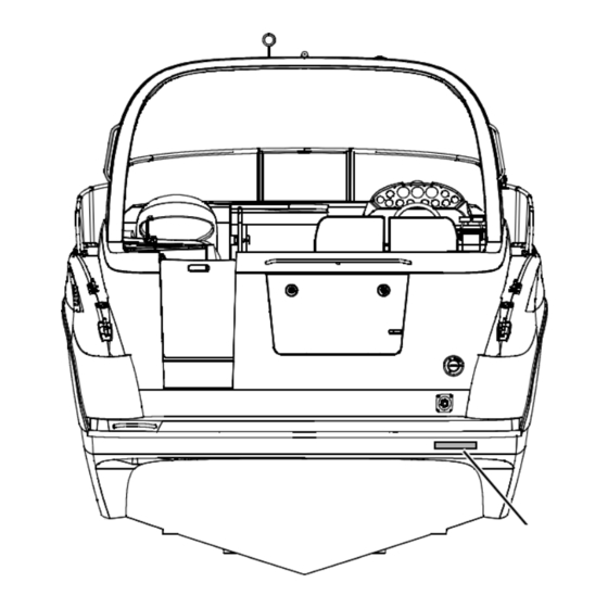
- Page 31 325 • Owner’s Manual Supplement Chapter 2: Locations Shore Power Inlet(s): Located inside the tran- som storage locker on the starboard side. SHORE POWER MASTER CIRCUIT BREAKER(S) SHORE POWER INLET(S) Shore Power Master Circuit Breaker(s): Located inside the transom storage locker on the starboard side.
- Page 32 Chapter 2: Locations 325 • Owner’s Manual Supplement Water Heater: Located on the port side of the engine room. WATER HEATER Windlass Circuit Breaker: Located in the engine room on WINDLASS CIRCUIT BREAKER the port hullside, above the bat- tery charger. BATTERY CHARGER Windlass Controls: •...
-
Page 33: Chapter 3: Propulsion & Related Systems
325 • Owner’s Manual Supplement Chapter 3: Propulsion & Related Systems Engines Read the engine operation and maintenance manuals before starting or working on the engines. Bilge Blower System WARNING! FIRE/EXPLOSION HAZARD • Use of the bilge blower system is NOT A GUARANTEE that explosive fumes have been removed. -
Page 34: Fuel System
Chapter 3: Propulsion & Related Systems 325 • Owner’s Manual Supplement Fuel System WARNING! FIRE, EXPLOSION, and OPEN FLAME HAZARD! • It is very important that the fuel system be inspected thoroughly the first time it is filled and at each subsequent filling. •... -
Page 35: Fuel Fill & Vent
325 • Owner’s Manual Supplement Chapter 3: Propulsion & Related Systems GAS ENGINES FUEL SYSTEM (IF EQUIPPED) FUEL TANK VENT HOSE ANTI-SIPHON VALVES & FUEL PICKUPS FUEL TANK STARBOARD ENGINE FUEL LINE INLINE FUEL FILTERS (MPI ENGINES ONLY) (IF EQUIPPED) PORT ENGINE FUEL LINE FUEL FILL HOSE VENTED FUEL FILL DECK FITTING... -
Page 36: Fuel Filter/Water Separators (Diesel Engines Only)
Chapter 3: Propulsion & Related Systems 325 • Owner’s Manual Supplement Fuel Filter/Water Separators (Diesel Engines Only) NOTICE • The frequency of water draining or element replacement is determined by the contamina- tion level in the fuel. • Inspect the collection bowls for water daily. •... -
Page 37: Quick Oil Drain System
325 • Owner’s Manual Supplement Chapter 3: Propulsion & Related Systems Quick Oil Drain System • A quick oil drain assembly is attached to the oil pan on each engine. • Some setup is needed before you can use this system. Setting Up the Quick Oil Drain System QUICK OIL DRAIN SYSTEM COMPONENTS BILGE PLUG... - Page 38 Chapter 3: Propulsion & Related Systems 325 • Owner’s Manual Supplement 3. Unclip the bilge plug swivel clip from the cable on the end of BILGE PLUG the oil drain hose. NOTE: This bilge OIL DRAIN plug assembly will SWIVEL CLIP HOSE CABLE be your spare.
-
Page 39: Using The Quick Oil Drain System
325 • Owner’s Manual Supplement Chapter 3: Propulsion & Related Systems 8. Repeat steps 2 through 7 on the port engine’s quick oil drain assembly. The only difference being; the bilge plug assembly, unclipped in step 3, will be used in step 9. •... -
Page 40: Engine Hatch Lift System (If Equipped)
Chapter 3: Propulsion & Related Systems 325 • Owner’s Manual Supplement Engine Hatch Lift System (If Equipped) NOTICE • Remove any items from the top of the engine hatch BEFORE Opening. • Close all entertainment center doors and hatches BEFORE Opening and/or Closing the engine hatch. -
Page 41: Chapter 4: Controls & Gauges
325 • Owner’s Manual Supplement Chapter 4: Controls & Gauges Steering • Your boat features a power assisted rack-and-pinion steering system. • For information about the 'power-assist fluid reservoir', refer to the engine operation and maintenance manual. • Boat steering is not self-centering. •... -
Page 42: Trim Tabs
Chapter 4: Controls & Gauges 325 • Owner’s Manual Supplement Trim Tabs WARNING! LOSS OF CONTROL HAZARD! Improper use of trim tabs WILL cause loss of control! • Do NOT allow anyone unfamiliar with trim tabs to use them. • Do NOT use trim tabs in a following sea as they WILL cause broaching or other unsafe han- dling characteristics. -
Page 43: Gauges
325 • Owner’s Manual Supplement Chapter 4: Controls & Gauges Gauges Cleaning the Gauges CAUTION PRODUCT or PROPERTY DAMAGE HAZARD! • Use only mild soap and water to clean the gauge lenses and bezels. • Use of other cleaners, including common window cleaning solutions, may cause the lenses to crack. -
Page 44: Chapter 5: Navigation & Communication Equipment
325 • Owner’s Manual Supplement Chapter 5: Navigation & Communication Equipment Read the manuals for all navigation & communication equipment before using these systems. Compass NOTICE • Compass accuracy can be affected by many factors. • Have a qualified technician calibrate your compass. •... -
Page 45: Global Positioning System (Gps) (If Equipped)
325 • Owner’s Manual Supplement Chapter 5: Navigation & Communication Equipment Global Positioning System (GPS) (If Equipped) WARNING! • The GPS system should NOT be relied upon as the ONLY aid to navigation. • A qualified operator MUST monitor the GPS system at ALL times and keep a look-out for other marine traffic and possible collision situations. -
Page 46: Chapter 6: Plumbing
325 • Owner’s Manual Supplement Chapter 6: Plumbing Bilge Pumps NOTICE Discharge of oil, oil waste, or fuel into navigable waters is prohibited by law. Violators are subject to legal action by the local authorities. • Your boat is equipped with two bilge pumps for pumping water out of the bilge. -
Page 47: Bilge Pump Testing
325 • Owner’s Manual Supplement Chapter 6: Plumbing Bilge Pump Testing • The bilge pumps are vital to the safety of your boat. • Test the bilge pumps often. 1. One at a time, turn On each bilge pump switch at the helm. 2. - Page 48 Chapter 6: Plumbing 325 • Owner’s Manual Supplement Autofloat Switches • The automatic bilge pumps use float (autofloat) switches to automatically turn On the pumps whenever water rises to a preset level in the bilge. • The autofloat switches are normally mounted next to the bilge pumps they control. •...
-
Page 49: Seawater Systems
325 • Owner’s Manual Supplement Chapter 6: Plumbing Seawater Systems Seacocks WARNING! FLOODING and SWAMPING HAZARD! • Close the seacock(s) when leaving your boat unattended for any length of time. • If a seacock is left open, a hose failure could flood the bilge, swamp the batteries and the engines, and even sink your boat. -
Page 50: Seawater Washdown
Chapter 6: Plumbing 325 • Owner’s Manual Supplement Seawater Washdown WARNING! FLOODING and SWAMPING HAZARD! • NEVER leave your boat unattended while using the seawater washdown system. • Any leak or break in this system may allow large amounts of water to flood the bilge, which could swamp the batteries and the engines, and even sink your boat. -
Page 51: Freshwater System
325 • Owner’s Manual Supplement Chapter 6: Plumbing Freshwater System WARNING! • ONLY use safe drinking (potable) water in your boat’s freshwater system. • ONLY use FDA approved "drinking water safe" hoses when filling the freshwater tank or connecting to city water. •... -
Page 52: Freshwater System Winterization
Chapter 6: Plumbing 325 • Owner’s Manual Supplement Freshwater System Winterization 1. Turn Off the water heater breaker switch. NOTE: Tag or Mark the water heater breaker switch to prevent it from being turned On while the water heater tank is empty. 2. -
Page 53: City Water Inlet
325 • Owner’s Manual Supplement Chapter 6: Plumbing City Water Inlet WARNING! FLOODING and SWAMPING HAZARD! • NEVER leave your boat unattended while the freshwater system is pressurized by city water. • Any leak or break in this system may allow large amounts of water to flood the bilge, which could swamp the batteries and the engines, and even sink your boat. -
Page 54: Water Heater
Chapter 6: Plumbing 325 • Owner’s Manual Supplement Water Heater WARNING! SCALDING HAZARD! Water heated by the water heater can be hot enough to scald the skin. CAUTION WATER HEATER DAMAGE HAZARD! • Do NOT turn On the water heater circuit breaker on the 110-volt AC master panel until the water heater tank is COMPLETELY filled with water. -
Page 55: Drain Systems
325 • Owner’s Manual Supplement Chapter 6: Plumbing Drain Systems Deck Drains VIEWS ARE UNDERSIDE OF DECK • Water on the deck is drained overboard WASHDOWN LOCKER DRAIN through the deck drains. • Keep the deck drains free of debris. TO THRU-HULL STORAGE LOCKER STORAGE LOCKER... -
Page 56: Shower Sump Pump System
Chapter 6: Plumbing 325 • Owner’s Manual Supplement Shower Sump Pump System • The shower drains into the sump pump box. • The sump pump box has an autofloat switch. • When the drain water rises to a preset level, the auto- float switch turns On the sump pump, and the drain water is pumped overboard. -
Page 57: Marine Head & Holding Tank
325 • Owner’s Manual Supplement Chapter 6: Plumbing Marine Head & Holding Tank NOTICE Check with local authorities for regulations regarding the legal use of marine head systems. Electric Flush Head with Holding Tank (If Equipped) WARNING! FLOODING and SWAMPING HAZARD! •... -
Page 58: Vacuum Flush Head System (If Equipped)
Chapter 6: Plumbing 325 • Owner’s Manual Supplement Vacuum Flush Head System (If Equipped) • Read the vacuum flush operation and maintenance manual. HEAD • The vacuum flush head system uses freshwater from the freshwater tank FRESHWATER HOSE and a vacuum pump to flush waste from the toilet into the holding tank. -
Page 59: Macerator (If Equipped)
325 • Owner’s Manual Supplement Chapter 6: Plumbing Macerator (If Equipped) To use the macerator to pump waste directly over- board (where regulations permit): FROM HEAD 1. Open the underwater UNDERWATER discharge seacock. DISCHARGE SEACOCK 2. Press both macerator switches at the same HOLDING TANK VENT time to run the pump. -
Page 60: Chapter 7: Deck Equipment
325 • Owner’s Manual Supplement Chapter 7: Deck Equipment Cleats & Tow Eyes WARNING! PERSONAL INJURY and/or PRODUCT or PROPERTY DAMAGE HAZARD! NEVER lift your boat using the bow and stern eyes or the cleats. Read the section on towing in the Cruiser & Yacht Owner’s Manual before: •... -
Page 61: Canvas
325 • Owner’s Manual Supplement Chapter 7: Deck Equipment Canvas CAUTION PRODUCT or PROPERTY DAMAGE HAZARD! Take down and securely stow ALL canvas BEFORE transporting your boat by road. NOTICE Two people are needed for most of the tasks listed in this section. NOTICE BEFORE cleaning and/or stowing your canvas or vinyl, read the sections later in this chapter, Canvas Care and Vinyl Care. -
Page 62: Camper Top (If Equipped)
Chapter 7: Deck Equipment 325 • Owner’s Manual Supplement Camper Top (If Equipped) NOTE: STARBOARD SIDE SHOWN, PORT SIDE TYPICAL 1. Slide the main bow’s end eyes into the forward hinges and insert the securing pins. 2. Unfold the camper top and, starting with the center snaps, snap the forward edge of the camper top to the radar arch. -
Page 63: Vinyl Curtains (If Equipped)
325 • Owner’s Manual Supplement Chapter 7: Deck Equipment Vinyl Curtains (If Equipped) Forward Bimini Curtain NOTICE When taking down the forward bimini curtain, avoid socket/stud problems by using the follow- ing method to unfasten the curtain sockets from the studs on the windshield frame: •... -
Page 64: Canvas Care
Chapter 7: Deck Equipment 325 • Owner’s Manual Supplement Canvas Care (see also ‘Clear Vinyl Care’ on next page) • After each use, especially in saltwater, rinse the canvas with cold freshwater. • Before stowing, let the canvas air-dry completely. •... -
Page 65: Clear Vinyl Care
325 • Owner’s Manual Supplement Chapter 7: Deck Equipment Clear Vinyl Care CAUTION • NEVER store the clear vinyl pieces wet, as this will cause a milky film to develop. • NEVER fold or crease the clear vinyl pieces as cracking will occur. •... -
Page 66: Chapter 8: Appliances & Entertainment Systems
325 • Owner’s Manual Supplement Chapter 8: Appliances & Entertainment Systems NOTICE ALWAYS keep an approved ABC-type fire extinguisher in galley area. • The separate instruction sheets or manuals for all appliances and entertainment systems contain detailed instruc- tions and important safeguards. •... -
Page 67: Chapter 9: Convertible Seats, Beds, & Tables
325 • Owner’s Manual Supplement Chapter 9: Convertible Seats, Beds, & Tables Dinette to V-berth Conversion 1. Pull out the table supports (A). 2. Turn control knob (B) on the table leg. 3. Lower the table top (C) by pushing down firmly. 4. -
Page 68: Lounge Conversion
Chapter 9: Convertible Seats, Beds, & Tables 325 • Owner’s Manual Supplement L-lounge Conversion 1. Remove table top (A). 2. Remove the two tall support posts (B). 3. Remove the two short support posts from the storage clips under the tran- som bench (C). -
Page 69: Cockpit Table Storage
325 • Owner’s Manual Supplement Chapter 9: Convertible Seats, Beds, & Tables Cockpit Table Storage 1. Remove table top (A) from the two support posts (B). 2. Remove the two support posts (B). 3. Place the two tall support posts (B) into the storage clips under the transom bench (C). -
Page 70: Chapter 10: Lights
325 • Owner’s Manual Supplement Chapter 10: Lights Care & Maintenance All of the lights installed on your boat are of top quality, but you should be aware that failure may periodically occur for a variety of reasons: 1. There may be a blown fuse - replace the fuse. 2. -
Page 71: Chapter 11: Air Conditioner System (If Equipped)
325 • Owner’s Manual Supplement Chapter 11: Air Conditioner System (If Equipped) DANGER! CARBON MONOXIDE POISONING HAZARD! • Dangerous carbon monoxide gas (CO) can be brought into your boat through the air conditioning system. • Read the Carbon Monoxide (CO) section of Chapter 1 in this supplement. CAUTION SYSTEM DAMAGE HAZARD! The air conditioning system’s seawater intake seacock MUST be Opened BEFORE turning On... -
Page 72: Chapter 12: Electrical System
325 • Owner’s Manual Supplement Chapter 12: Electrical System DANGER! EXTREME FIRE, SHOCK & EXPLOSION HAZARD! • To minimize the risks of fire and explosion, NEVER install knife switches or other arcing devices in the fuel compartment. • NEVER substitute automotive parts for marine parts. Marine electrical, ignition and fuel system parts were designed and manufactured to comply with rules and regulations that minimize risks of fire and explosion. -
Page 73: 12-Volt Dc System
325 • Owner’s Manual Supplement Chapter 12: Electrical System 12-Volt DC System Batteries • The batteries supply electricity for lights, 12-volt accessories, engine starting and, if equipped, generator starting. • The Electrical section of Chapter 8 in the Cruiser & Yacht Owner’s Manual provides battery care and mainte- nance instructions. -
Page 74: Battery Switches
Chapter 12: Electrical System 325 • Owner’s Manual Supplement Battery Switch Positions NOTICE Since your boat’s batteries were installed by your dealer, the battery switch positions listed below may vary. Make sure your selling dealer fully explains how to use the battery switches. ENGINE ACCESSORIES BATTERY... - Page 75 325 • Owner’s Manual Supplement Chapter 12: Electrical System Battery Charger (If Equipped) CAUTION ENGINE and ELECTRICAL SYSTEM DAMAGE HAZARD! NEVER run your boat’s engines and the battery charger at the same time. CAUTION • The battery charging systems (alternator and battery charger) installed on your boat are designed to charge conventional lead-acid batteries.
-
Page 76: 110-Volt Ac System
Chapter 12: Electrical System 325 • Owner’s Manual Supplement 110-Volt AC System WARNING! FIRE and ELECTRICAL SYSTEM DAMAGE HAZARD! If equipped with a generator, using both shore power and generator power at the same time WILL cause major electrical system damage and could start a fire! •... -
Page 77: Shore Power
325 • Owner’s Manual Supplement Chapter 12: Electrical System Shore Power DANGER! FIRE, EXPLOSION and SHOCK HAZARD! • Do NOT alter the shore power connectors and use ONLY compatible connectors. • Turn Off ALL breakers and switches on the 110-volt AC master panel BEFORE plugging in or unplugging the shore power cord. -
Page 78: Connecting To Shore Power
Chapter 12: Electrical System 325 • Owner’s Manual Supplement • Single shore power 110-volt/60-hertz AC systems feature one 110-volt/30-amp shore power receptacle. • If your boat has an air conditioning system, a second (dual) 110-volt/30-amp inlet has been installed. • Dual shore power inlets are labeled LINE 1 and LINE 2, which corresponds to the SHORE POWER 1 and SHORE POWER 2 master breakers on the 110-volt AC master panel. -
Page 79: Generator (If Equipped)
325 • Owner’s Manual Supplement Chapter 12: Electrical System Generator (If Equipped) DANGER! CARBON MONOXIDE POISONING HAZARD! • Generators are a source of dangerous carbon monoxide gas (CO). Check the generator exhaust system for leaks BEFORE each use. • Read the Carbon Monoxide (CO) section of Chapter 1 in this supplement. WARNING! FIRE/EXPLOSION HAZARD! •... - Page 80 Chapter 12: Electrical System 325 • Owner’s Manual Supplement GAS GENERATOR SYSTEM SEAWATER ANTI- FUEL SIPHON VALVE FILTER GENERATOR EXHAUST THRU-HULL SEAWATER STRAINER SEAWATER FUEL PICKUP MUFFLER INTAKE SEACOCK & ANTI-SIPHON VALVE DIESEL GENERATOR SYSTEM SEAWATER ANTI- FUEL FEED SIPHON VALVE LINE FUEL FILTER/ FUEL RETURN...
-
Page 81: Electrical Routings
325 • Owner’s Manual Supplement Chapter 12: Electrical System Electrical Routings 12-Volt DC Deck Harnesses VIEW IS UNDERSIDE OF DECK WINDLASS FOOT CONTROLS SPOTLIGHT (IF EQUIPPED) PORT NAVIGATION LIGHT STARBOARD NAVIGATION LIGHT WINDLASS V-BERTH LIGHT V-BERTH LIGHT AUDIO/VISUAL PANEL SALON LIGHTS V-BERTH CO MONITOR STARBOARD SPEAKER PORT SPEAKER... -
Page 82: 12-Volt Dc Hull Harnesses
Chapter 12: Electrical System 325 • Owner’s Manual Supplement 12-Volt DC Hull Harnesses SEAWATER WASHDOWN INTAKE SEACOCK BONDING SEAWATER WASHDOWN PUMP COURTESY LIGHT GALLEY PORT STARBOARD HEAD SHOWER DRAIN SUMP PUMP FORWARD BILGE PUMP HEAD INTAKE SEACOCK BONDING HELM FIRE INDICATOR (IF EQUIPPED) ENGINE HATCH LIFT PUMP (IF EQUIPPED) -
Page 83: 110-Volt Ac Deck Harnesses
325 • Owner’s Manual Supplement Chapter 12: Electrical System 110-Volt AC Deck Harnesses VIEW IS UNDERSIDE OF DECK 110-VOLT AC MASTER PANEL STARBOARD PORT SHORE POWER INLET(S) & SHORE POWER MASTER BREAKER(S) -
Page 84: 110-Volt Ac Hull Harnesses
Chapter 12: Electrical System 325 • Owner’s Manual Supplement 110-Volt AC Hull Harnesses PORT STARBOARD GALLEY RECEPTACLE 110-VOLT AC MASTER PANEL DINETTE RECEPTACLE REFRIGERATOR MICROWAVE ELECTRIC STOVE AIR CONDITIONER CONTROL PANEL (IF EQUIPPED) AFT BERTH RECEPTACLE AIR CONDITIONER UNIT (IF EQUIPPED) BATTERY CHARGER AIR CONDITIONER SEAWATER PUMP... -
Page 85: Battery Cable System
325 • Owner’s Manual Supplement Chapter 12: Electrical System Battery Cable System NOTES: POSITIVE BATTERY CABLES ARE RED POSITIVE: NEGATIVE BATTERY CABLES ARE YELLOW NEGATIVE: 12-VOLT DC PUSH-TO-RESET CIRCUIT BREAKERS BUSS BAR HOUSE BATTERY PORT ENGINE & GENERATOR BATTERY BATTERY SWITCH PANEL GENERATOR (IF EQUIPPED) -
Page 86: Wiring Diagrams
Chapter 12: Electrical System 325 • Owner’s Manual Supplement Wiring Diagrams Engine Electrical Systems... -
Page 87: 12-Volt Dc System
325 • Owner’s Manual Supplement Chapter 12: Electrical System 12-Volt DC System... -
Page 88: 110-Volt Ac System, Single Shore Power
Chapter 12: Electrical System 325 • Owner’s Manual Supplement 110-Volt AC System, Single Shore Power... -
Page 89: 110-Volt Ac System, Dual Shore Power
325 • Owner’s Manual Supplement Chapter 12: Electrical System 110-Volt AC System, Dual Shore Power... -
Page 90: Important Records
325 • Owner’s Manual Supplement Important Records Selling Dealer Key Numbers Name Of Dealership Ignition Other Address Electronics Phone/FAX/E-mail Manufacturer Model Name/Number Sales Manager Serial Number Service Manager Manufacturer Model Name/Number Engines Serial Number Port Engine Serial Number Starboard Engine Serial Number Oil Type/SAE Quarts per Engine Filter Type... -
Page 91: Float Plan
325 • Owner’s Manual Supplement Float Plan Before going boating, fill out a copy of this float plan (or similar) and leave it with a reliable person whom you can depend on to contact the Coast Guard or other rescue organization, if you do not return as scheduled. Description of Boat Persons Onboard Registration/Documentation Number... - Page 92 Float Plan 325 • Owner’s Manual Supplement Survival Equipment Trip Expectations Marine Radio (Yes/No) Type Frequencies Departing From Number of PFDs Flares (Yes/No) Mirror (Yes/No) Departure Date Departure Time Smoke Signals (Yes/No) Flashlight (Yes/No) Food (Yes/No) Stopover 1 Water (Yes/No) Anchor (Yes/No) Raft/Dinghy (Yes/No) Arrive No Later Than: Date...
- Page 93 Owner’s Notes...
- Page 94 Owner’s Notes...
- Page 96 Bayliner • P.O. Box 9029 • Everett, WA 98206 • 360-435-5571...
Need help?
Do you have a question about the 325 Cruiser and is the answer not in the manual?
Questions and answers