Advertisement
Table of Contents
- 1 Wiring Diagram
- 2 Table of Contents
- 3 Instructions for Wiring Diagram
- 4 Preparations for Installation
- 5 Positioning of the Alarm Units
- 6 Attention
- 7 User Instructions
- 8 Coding New Remote Control Units
- 9 Connection of Central Locking
- 10 Programming of Alarm
- 11 Technical Data
- 12 Approval
- Download this manual
See also:
User Manual
Advertisement
Table of Contents

Related Manuals for DEFA 800 Series


Summary of Contents for DEFA 800 Series
- Page 1 Installation Manual, DEFA Auto Security Car Alarm 800 Series 8028 (D11)
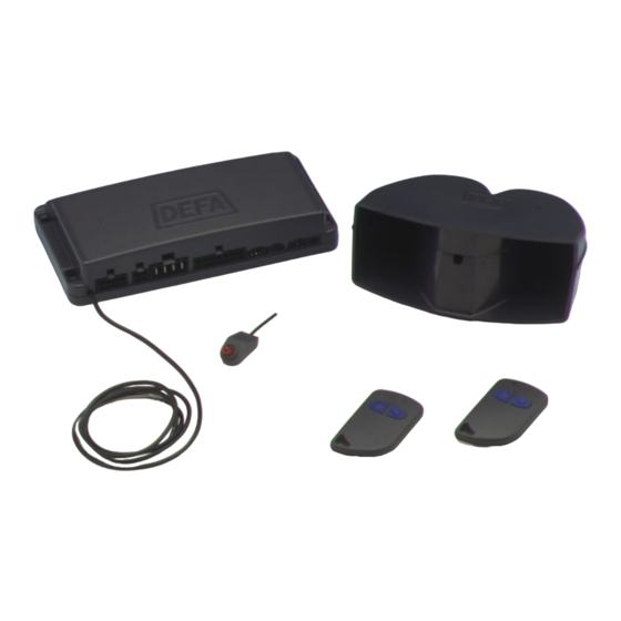
- Page 2 DEFA Auto Security 800 Series Glassbreake Microwave Backup Immobilizer Sensor Sensor Alarm Module 8028 (D10)
-
Page 3: Wiring Diagram
Wiring diagram... - Page 4 Tools...
-
Page 5: Table Of Contents
Contents Wiring diagram Page 3 Instructions for wiring diagram Page 6-8 Preparations for installation Page 9 Positioning of the Alarm Units Page 9-10 Attention! Page 10 User instructions Page 11-12 Coding new Remote Control Units Page 13 Connection of Central Locking Page 13-14 Programming of alarm Page 15-19... -
Page 6: Instructions For Wiring Diagram
The other lead end (50) leading to the starter is connected to P-3.4 white/green lead. P-4.1 Channel 3 Output for the Remote Control of the electric DEFA Car Heating System. When activated, the output supplies +12V until the function is deactivated again. Maximum load: 350 mA. P-4.2 Channel 2 When activated, the output is grounded until the button is pressed. - Page 7 This input is normally open (NO) and triggers the alarm when connected to ground, i.e. when the bonnet is opened. Install DEFA Bonnet Switch. This should be installed in such a position as to make it inaccessible from either the underside or the front of the car.
- Page 8 Plug for auxiliary Sensors Cf. separate assembly instructions. Plug for Glassbreake Sensor Standard for all models with the letter G in the model designation. If a window is broken, the Glassbreake Microphone triggers the alarm. Plug for Microwave Sensor Standard for all models with the letter M in the model designation. If the sensor detects motion in the vehicle interior, the alarm is triggered.
-
Page 9: Preparations For Installation
Immobilizers; if this is not the case, the Alarm will not be subject to type approval. A list of recognised original start lock systems is available from DEFA or the DEFA representative in your country. -
Page 10: Attention
The position of the antenna is a major influence on its range. Alarm signs (decals) Attach DEFA Auto Security decals to both the front side windows and to the windscreen or rear screen. Important: The decals must not obscure the driver’s line of sight. -
Page 11: User Instructions
User Instructions Further information, see technical manual. Your DEFA Auto Security Alarm is activated using the two buttons (A and B) on the Remote Control. The two buttons are easy to tell apart, as button A is noticeably higher. Button A Button B «Press»... - Page 12 DEFA Central Unit 821X P/N:10011 D S/N: 1234567 PIN-kode: X- X- X- X- X Manufactured by DEFA A.S, Norway DEFA Hotline : 4732771540 1. Unlock and open the car door. The Alarm is activated ! 2. Turn the ignition ON and OFF five times in a row.
-
Page 13: Coding New Remote Control Units
Coding of new Remote Control Units Further information, see technical manual. Press button B to switch the alarm and the Immobilizer (if present) OFF. The emergency deactivation can also be used. Switch the ignition ON and OFF 5 times. The LED flashes rapidly. When you switch the ignition ON again, the LED should flash. - Page 14 The circuit diagrams below show the usual circuit options. UNLOCK LOCK UNLOCK LOCK +12V +12V BLUE GREEN To DEFA central lock motor A : LOCK AND UNLOCK UNLOCK LOCK UNLOCK LOCK +12V +12V A : LOCK B : UNLOCK B : UNLOCK...
-
Page 15: Programming Of Alarm
Programming the alarm Further information, see technical manual. The alarm contains a register that allows various functions to be programmed or altered using the Remote Control and the ignition key. Please read the detailed function description on the following pages. Function Description Cause of Alarm trigger... - Page 16 Function 1: Cause of Alarm trigger Press button A to obtain information about the cause of the alarm last triggered. Press button B for information about the alarm triggered previously. Hold button B to return to the last alarm. Hold buttons A and B simultaneously to delete the trigger cause memory. The Central Unit can store up to 10 alarm events.
- Page 17 Function 6: Setting of Remote Control with Slider Switch The Remote Control with Slider Switch can be programmed for 3 different modes: Programming Press A Hold A Press B Hold B Position of Slider Switch 1 flash Alarm Close Alarm Windows open windows Close sliding...
- Page 18 2 flashes = Convenience closing via the original system 3 flashes = Convenience closing via DEFA Power Module, closes only electric window winders Press button B again to select the next convenience closing mode or hold button B to select the preceding one.
- Page 19 Press button B to indicate the current setting. 1 flash = Function is not selected 2 flashes = Panic function is active when buttons A and B are held simultaneously (standard) 3 flashes = Panic function is activated for 30 seconds after buttons A and B were held simultaneously.
-
Page 20: Technical Data
Technical data Central Unit, 800 series Operating voltage: 9-15 V d.c. Operating temperature: -40°C to +85°C Exterior dimensions: 159 x 80 x 34 mm Power consumption Armed Disarmed 820/821X-G: 13 mA 18 mA 820/821X-M: 19 mA 18 mA 820/821X-MG: 19 mA...
Need help?
Do you have a question about the 800 Series and is the answer not in the manual?
Questions and answers