
Related Manuals for CTC Union FMUX04


Summary of Contents for CTC Union FMUX04
- Page 1 USER MANUAL FMUX04 Fiber Optical Multiplexer Standalone / Rack Type 4 Channel Fixed Design G.703 E1, T1(DS1) SNMP Manageable (Optional) FXS Order Wire (Optional)
- Page 3 The information contained in this document is subject to change without prior notice. TRADEMARKS Microsoft is a registered trademark of Microsoft Corp. HyperTerminal™ is a registered trademark of Hilgraeve Inc. WARNING: This equipment has been tested and found to comply with the limits for a Class A digital device, pursuant to Part 15 of the FCC Rules.
- Page 4 CTC Union Technologies Co., Ltd. Far Eastern Vienna Technology Center (Neihu Technology Park) 8F, No. 60, Zhouzi St. Neihu, Taipei, 114 Taiwan Phone: +886-2-2659-1021 FAX: +886-2-2799-1355 FMUX04 User Manual Fiber Multiplexer with 4 channels E1 or T1 Version 1.0 Mar 2006...
-
Page 5: Table Of Contents
3.1 Introduction ........................23 3.2 DIP Switch Setting Detail..................... 23 3.3 Terminal Mode Operation ................... 24 3.4 Connecting to the FMUX04 ..................24 3.5 Configuring in Console Mode ..................25 3.5.0 Local or Remote Login..................25 3.5.1 Display System Status ................... 26... - Page 6 Table of Contents 3.5.2 Define System Parameters ..................27 3.5.3 Display Alarm Record ................... 35 3.5.4 Device Information ....................35 3.6 Remote Configuration....................36 Chapter 4. SNMP........................37 4.1 General......................... 37 4.2 SNMP Operations ......................37 4.3 The Management Information Base................37 4.4 MIB Structure .......................
-
Page 7: Chapter 1. Introduction
Chapter 1: Introduction Chapter 1. Introduction Thank you for choosing the FMUX04. If you would like to skip right to the installation and configuration of the Multiplexer, proceed to Chapters 2 and 3. This manual is used to explain the installation and operating procedures for the FMUX04, 4 Port Fiber Optical E1/T1 Multiplexer, and present its capabilities and specifications. - Page 8 Chapter 1: Introduction When configured for E1 operation, the 4 channels of the FMUX04 may use either BNC (75 Ohm unbalanced) or RJ-45 (120 Ohm balanced) connectors for E1 Line interface connections. Each separate E1 channel supports a transmission rate of 2.048Mb/s (transparent unframed E1) each.
-
Page 9: Features List
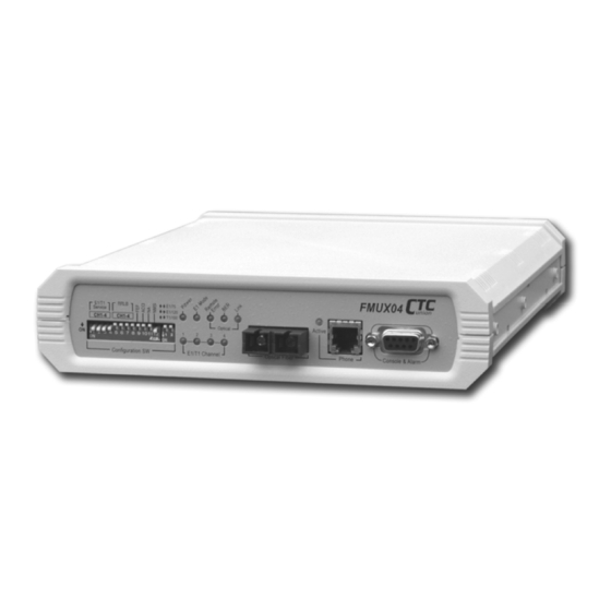
When the FMUX04 is ordered with optional Order Wire, a hardware card is installed inside the unit. The front panel's RJ-11 jack provides a "hot line" between the two FMUX04 units in the link. Standard telephones may be connected to the RJ-11 jacks and when a phone is taken "off hook", the remote side will automatically ring. - Page 10 Chapter 1: Introduction The following photo (AC model), with graphics, shows the major components which make up the FMUX04 (with the Order Wire and SNMP options installed). AC Power Switch SNMP Ethernet jack Switching Power (AC) E1 BNC Connectors E1 RJ45 Connectors...
-
Page 11: Technical Specifications
Chapter 1: Introduction 1.5 Technical Specifications 1.5.1 E1 Link Ports 4 fixed ports Framing Unframed (transparent) Bit Rate 2.048 Mb/s +/-50ppm Line Code HDB3 Line Impedance Unbalanced 75 ohms (BNC) Balanced 120 ohms (RJ-45) Receiver sensitivity -43dB (long haul) "Pulse" Amplitude Nominal 2.37V+/-10% for 75 ohms Nominal 3.00V+/-10% for 120 ohms "Zero"... -
Page 12: Local Setup And Configuration
Chapter 1: Introduction 1.5.3 Local Setup and Configuration DIP Switches A switch -12 pole, B switch - 2 pole Console Port local VT-100 terminal connection 1.5.4 RS-232 Console Port Port interface V.24/RS-232 asynchronous, DCE Port connector DB9F Data rate (*default) 19200 bps Data format -One start bit... -
Page 13: Optical Specifications
Chapter 1: Introduction 1.5.6 Optical Specifications Connector Type ST, SC, FC, LC, MT-RJ or WDM-SC (single fiber) Optical mode Multi-mode or Single-mode Wavelength 1310nm or 1550nm Power Margin 11dB(2k,M/M), 12dB~35dB(15~120KM,S/M) Line coding Scrambled NRZ Data rate 10.922 Mbps Bit Error rate Less than 10 Test Loops LLB (Local Loop Back) -
Page 14: Power Supply
Chapter 1: Introduction 1.5.9 Power supply Voltage (AC source) 100 ~ 240 VAC Voltage (DC range 1) 18 ~ 36 VDC Voltage (DC range 2) 36 ~ 72 VDC Frequency 47 to 63 Hz for AC power Power consumption 15 VA maximum 1.5.10 Environment Temperature 0-50... -
Page 15: T1(Ds1) Signal Structure
T1 equipment is to transparently pass timing from a timing source unit on one side, to a timing slaved unit on the other. Each of the up to 4 available channels of the FMUX04 is independent of any other channel for transparent framing or timing. - Page 16 Chapter 1: Introduction This page left blank intentionally.
-
Page 17: Chapter 2. Installation
Antistatic mat or antistatic foam to set the equipment on. 2.2 Site Preparation Install the FMUX04 within reach of an easily accessible grounded AC outlet or site DC power. The outlet should be capable of furnishing 100 to 240 VAC (18 to 36VDC or 36 to 72 VDC for DC supply). -
Page 18: Mechanical Assembly
Chapter 2. Installation 2.4 Mechanical Assembly The FMUX04 is designed for standalone use, but it may be rack mounted as required with an optional mounting kit. The rack installation only requires 1U space (1 3/4") in a standard EIA 19 inch rack. The FMUX04 is delivered completely assembled. No provision is made for bolting the FMUX04 to a tabletop. -
Page 19: Electrical Installation
2.5 Electrical Installation 2.5.1 Power connection, AC For a model with AC power supply, AC power (100~240VAC) is supplied to the FMUX04 through a becoming standard clover leaf 3-prong receptacle, located on the rear of the unit. The FMUX04 should always be grounded through the protective earth lead of the power cable in AC installations. -
Page 20: Rear Panel Connectors
Chapter 2. Installation 2.6 Rear Panel Connectors The rear panel of the FMUX04 supports the E1 and T1 interface connection, the AC or DC power connectors, the power switch and the Ethernet connector for connection to the LAN network for SNMP control (when the SNMP option is installed). The FMUX04 routes the signals from the 4 E1/T1 channels to the multiplexing circuitry and sends the multiplexed signals to the Fiber Interface on the front panel. -
Page 21: Removal/Replacement Procedures
The front panel RJ-11 telephone connector routes to the OW (Order Wire) interface PCB. The OW option provides a standard FXS connection that links to the remote FMUX04 unit via the fiber optical interface. Calls are placed simply by lifting the telephone off-hook. The remote telephone will ring. -
Page 22: Snmp Feature Removal / Replacement
1. If the unit is installed in a rack, remove all connections and power cord. 2. Loosen the captive thumb screws on the rear of the FMUX04 until the threads are disengaged from the housing. -
Page 23: Chapter 3. Operation
* When set to DIP Switch Configuration mode, the serial terminal cannot connect to the FMUX04. Any DIP switch change is immediately recognized without any need to power restart the FMUX04. When set to Console and SNMP mode, any other setting of DIP switches is completely ignored. -
Page 24: Terminal Mode Operation
FMUX04 is very straight forward. The only hardware required is a DB9M to DB9F adapter cable (see pinout below). The FMUX04's RS-232 Console port acts as a DCE to the PC's DTE communications port. A convenient application, provided with the Microsoft Windows®... -
Page 25: Configuring In Console Mode
Chapter 3. Operation 3.5 Configuring in Console Mode The FMUX04 Control Port (labeled Console & Alarm on the front panel) is a console terminal port designed to facilitate setup of all parameters through the use of a standard text based terminal or any terminal emulation program running on a Personal Computer. Make the appropriate connections, start the terminal application, apply power to the FMUX04, then press ENTER on the PC keyboard. -
Page 26: Display System Status
3. Display Alarm Record 4. Device Information Please select the item 0~4 3.5.1 Display System Status From the main root menu, select "1" to display the real-time status of the FMUX04. LOCAL << Display System Status >> 2006/02/16 16:03:06 +--------------------+-------------------+-------------------+... -
Page 27: Define System Parameters
The 'Define System Parameter' menu is the main gateway to doing all configuration of the FMUX04. From the main menu, pressing '2' will directly enter the 'Define System Parameter' menu. Note that the upper left corner will display the word "LOCAL" in inverse text, indicating that the Terminal Mode connection is to the local unit and not the remote unit. - Page 28 Chapter 3. Operation 3.5.2.1 System Configuration Use the System Configuration menu option to save and load the single user setting, to load the factory default settings, to clear the Alarm buffer or to modify the login password. LOCAL << System Configuration >> 1.
- Page 29 Chapter 3. Operation Loopback Descriptions * LLB (Optical local loop back) near end (NE) far end (FE) * RLB (Optical Remote loop back) near end (NE) far end (FE) * RRLB (Request optical remote loop back) near end (NE) far end (FE) FEF (Far End Fault) The FEF function lets the receiving unit advise the far end unit that it has lost the receive optical signal.
- Page 30 Chapter 3. Operation 3.5.2.3 E1/T1 Configuration LOCAL << E1/T1 Configuration >> 1. CH1 2. CH2 3. CH3 4. CH4 ------------------------------------------------------- 5. Service 6. Line Code HDB3 HDB3 HDB3 HDB3 7. Loopback 8. Termination Type E1/75/BNC ------------------------------------------------------- Please select 1~4 (Channel) or 8 (Termination Type) or [ESC] to previous menu.
- Page 31 The fourth item from the ''Configure System Status' menu is the Phone Configuration. The FMUX04 has the option of installing an Order Wire feature that will allow voice connection between both near and far end units using standard telephone handsets. The phone function...
- Page 32 The sixth item on the 'Configure System Status' menu is the date and time setting function. The FMUX04 has a battery backed up real time clock that is used for time-stamping performance monitored data and alarm events. Select "1" to set the date and select "2" to set the time.
- Page 33 FMUX04. The 'FPGA Firmware' is the code that loads into the field programmable gate array at startup. The FPGA is the physical heart of the FMUX04, it provides the logic for the multiplexing of the E1/T1 signals, controls the loop back functions, provides the optical scrambling and integrated BERT among many other things.
- Page 34 Chapter 3. Operation Upgrade Procedure Select the upgrade option; "1" upgrade the mainboard firmware, or "2" upgrade the FPGA firmware. Answer "y" to the confirmation message "Are your sure ….." Now start the Xmodem file transfer. Here is an example using HyperTerminal. 1.
-
Page 35: Display Alarm Record
Chapter 3. Operation 3.5.3 Display Alarm Record From the main login page, press "3" to display the alarm record. LOCAL << Display Alarm Record >> <Channel> <Alarm Type> <Alarm ON/OFF> <DATE> <TIME> Optical Signal Loss 2006/02/21 11:35:44 Port 2 BPV Error 2006/02/21 11:35:44 Port 2... -
Page 36: Remote Configuration
Chapter 3. Operation 3.6 Remote Configuration From the main login page select the second option "2", Remote Login. REMOTE ******************************************* **** CTC UNION TECHNOLOGIES CO.,LTD **** **** FMUX04 CONSOLE MODE Ver 1.00 **** **** <http://www.ctcu.com> **** ******************************************* 0. Logout 1. Display System Status 2. -
Page 37: Chapter 4. Snmp
The SNMP management functions of the FMUX04 are provided by an internal SNMP agent, which utilizes out-of-band communication over standard 10Base-T or 100Base-TX Ethernet. The SNMP agent is compliant with the SNMPv1 standard. SNMP communications use the User Datagram Protocol (UDP). -
Page 38: Mib Structure
Enterprise-specific MIB's are published and distributed by their creators, who are responsible for their contents. The MIB supported by the FMUX04 SNMP Agent follows RFC 1158 (MIB-II standard). 4.5 SNMP Communities To enable the delimitation of management domains, SNMP uses "communities". Each community is identified by a name, which is an alphanumeric string of up to 255 characters defined by the user. -
Page 39: Configuring The Snmp Agent
RS-232 Control Port of the FMUX04. Refer to Chapter 3, section 3.5 for operation of the console for the FMUX04 and the login procedures. From the 'Configure System Status' menu select "7", SNMP Configuration. Note: No SNMP configuration is available when logged into the unit. -
Page 40: Configure The Snmp Agent
Item number 3, is the default gateway for the network that the card is attached to and is required if the FMUX04 is to be managed from a different subnet. HINT: when entering IP addresses, enter without "dots" and include any leading zeros. -
Page 41: Tftp Server Configuration
('secret' in this case) and read only ('public') access, and assigning a community string to an access IP, an administrator can control access to the FMUX04. HINT: when entering IP addresses, enter without "dots" and include any leading zeros. -
Page 42: Save Configuration And Reboot The Snmp
Chapter 4. SNMP 4.6.4 Save Configuration and Reboot the SNMP LOCAL << SNMP Configuration >> 1. SNMP Agent Configuration 2. Manager Configuration 3. TFTP Server Configuration 4. Save Configuration and Reboot the SNMP 5. TFTP and Upgrade Firmware Press <ESC> to previous menu. ======================================= Saving the SNMP configuration, Please wait ... - Page 43 Chapter 4. SNMP LOCAL << TFTP and Upgrade Firmware >> 1. Upgrade the SNMP Firmware 2. Upgrade the Main Board Firmware 3. Upgrade the FPGA Firmware Press <ESC> to previous menu. Make sure the TFTP server is running and enter your choice of upgrade item. LOCAL <<...
- Page 44 Chapter 4. SNMP CTC Union provides a TFTP utility program that runs standalone in Windows® without any installation. We recommend that you copy the program and any binary image files for upload to your Windows® desktop for convenience sake. If you place the binary files and server program in the same directory, there is no need to enter any path information in the SNMP agent.
-
Page 45: Mib File
The following graphic shows the MG-SOFT MIB Browser software, after importing and compiling the MIB file, accessing the FMUX04 and doing an 'SNMP Walk' on the local E1 configuration OID. The query results are shown on the right screen. -
Page 46: Web Based Interface
4.8.1 Security Login To connect to the FMUX04 use the device's IP address as the URL location. For example with our setup unit, enter http://192.168.0.253/ and Enter. A login security prompt will display. -
Page 47: Display System Status
Chapter 4. SNMP 4.8.3 Display System Status The default page shown will be the Display System Status page. Note that the navigation menu is in the frame on the left side. The 'Local' designation means we are viewing the local unit (from the SNMP card's standpoint). -
Page 48: System Configuration
Chapter 4. SNMP 4.8.5 System Configuration The System Configuration page is used to save and load user settings, load default settings, clear the alarm buffer record and change the login password. (refer to 3.5.2.1) 4.8.6 Optical Configuration The Optical Configuration page allows enabling the FEF function, clearing the BER Alarm and setting the optical loop backs. -
Page 49: E1/T1 Configuration
Chapter 4. SNMP 4.8.7 E1/T1 Configuration The E1/T1 configuration page sets the channel service, line code and termination type for the E1/T1. It also sets the loop back types (see 3.5.2.3). 4.8.8 Phone Configuration The Phone Configuration allows enabling or disabling the phone function, if the order wire phone option is installed. -
Page 50: Alarm Configuration
Chapter 4. SNMP 4.8.9 Alarm Configuration The Alarm Relay page allows enabling or disabling the alarm relay function. (refer to 3.5.2.5) 4.8.10 Date & Time The Date & Time page allow setting the real time clock. The clock is used for timestamping alarm and performance data. -
Page 51: Snmp Setup
Chapter 4. SNMP 4.8.11 SNMP Setup 4.8.11.1 SNMP Agent Configuration Configures the agent IP, subnet mask and default gateway. (refer to 4.6.1) 4.8.11.2 Manager Configuration Configures the information for up to 4 management workstations, plus the community strings. - Page 52 Chapter 4. SNMP 4.8.11.3 TFTP Server Configuration Configures the SNMP card for TFTP upgrade. (refer to 4.6.3) 4.8.11.4 Save Configuration and Reboot The Save Configuration page allows the settings to be written to non-volatile flash followed by rebooting of the SNMP agent. (refer to 4.6.4)
-
Page 53: Display Alarm Status
Chapter 4. SNMP 4.8.11.5 TFTP and Upgrade Firmware Once TFTP is properly configured, this page is used to execute the upgrade for SNMP, mainboard firmware or main unit FPGA firmware. (refer to 4.6.5) 4.8.12 Display Alarm Status This option page will display the contents of the alarm buffer, with newest entries at the bottom. -
Page 54: Display Information
This completes the review of the Web based management features of the FMUX04. 4.9 Telnet Management When the SNMP option is installed in the FMUX04, Telnet connection is available for console type management. Choosing a Telnet client is important to get the proper display from the SNMP agent. - Page 55 Chapter 4. SNMP Set IP login Password The above examples are Telnet using Windows HyperTerminal utility. The screen displays in Telnet are the same as those from local console (RS-232) connection. (Please refer to 3.3 Terminal mode for operation details)
-
Page 56: Appendix A. Miscellaneous
Appendix A. Miscellaneous Appendix A. Miscellaneous A.1 Console port pin assignment The console port on the FMUX04 serves two purposes; it provides the RS-232 communication interface for terminal configuration and also contains one set of relay contacts for alarm. Signal... -
Page 57: Console Cable Pin Assignment Cab-Db9Db9F-232-3
Alarm 100cm 20cm A.4 Phone pin assignment The phone connector is a standard RJ-11 telephone connector located on the front panel of the FMUX04. The center two pins connect to a standard dial telephone. Signal Description No connection No connection... -
Page 58: Snmp Rj-45 Pin Assignment
Appendix A. Miscellaneous A.6 SNMP RJ-45 pin assignment Signal Description Transmit (+)* Transmit (-)* Receive (+)* No connection No connection Receive (-)* No connection No connection (standard Ethernet connection) *The Ethernet interface actually supports auto-MDIX and auto polarity. A.7 SNMP Trap Messages and Alarms Trap Code Description Alarm... -
Page 59: Snmp Object Details
Appendix A. Miscellaneous A.8 SNMP Object Details Path=iso.org.dod.private.enterprise.ctc.fmux04.local Object Identifier Object Type stat Parameters Local_system_Configuration local_save_User_Setting 0 - disable 1 - enable local_load_User_Setting 0 - disable 1 - enable local_load_Default_Setting 0 - disable 1 - enable local_load_snmp_Default_Setting 0 - disable... - Page 60 6 - phone local_device_information local_phone_module 0 - not_exist 1 - exist local_main_version Octet string local_fpga_version Octet string local_snmp_version Octet string Path=iso.org.dod.private.enterprise.ctc.fmux04.remote The remote follows the same object structure as the local. Except * remote optical local loopback is RO (read only).
- Page 62 Fiber Converter Series CTC Union Technologies Co., Ltd. Far Eastern Vienna Technology Center (Neihu Technology Park) 8F, No.60, Zhouzi Street Neihu, Taipei, Taiwan Phone:(886) 2.2659.1021 Fax:(886) 2.2799.1355 E-mail: info@ctcu.com http://www.ctcu.com...
Need help?
Do you have a question about the FMUX04 and is the answer not in the manual?
Questions and answers