
Related Manuals for CTC Union FMUX-01A


Summary of Contents for CTC Union FMUX-01A
- Page 1 USER MANUAL FMUX-01A Fiber Optical Multiplexer Standalone / Rack Type 4, 8, 12 or 16 Channel Modular Design G.703 E1, T1(DS1) Datacom V.35, X.21, RS-530, RS-449, RS-232 Ethernet 10/100Base-TX Bridge SNMP Manageable...
- Page 3 CTC Union Technologies assumes no responsibility, however, for possible errors or omissions, or for any consequences resulting from the use of the information contained herein. CTC Union Technologies reserves the right to make changes in its products or product specifications with the intent to improve function or design at any time and without notice and is not required to update this documentation to reflect such changes.
- Page 4 CTC Union Technologies Co., Ltd. Far Eastern Vienna Technology Center (Neihu Technology Park) 8F, No. 60, Zhouzi St. Neihu, Taipei, 114 Taiwan Phone: +886-2-2659-1021 FAX: +886-2-2799-1355 FMUX-01A Platform fiber multiplexer with 4, 8, 12, 16 channels E1, T1, Data communication, or 10/100Base-TX Ethernet Bridge.
-
Page 5: Table Of Contents
Table of Contents Chapter 1. Introduction 1.1 General ............................1 1.2 Functional Description ......................1 1.3 Technical Specifications ......................4 1.4 E1 Signal Structure........................8 1.5 T1(DS1) Signal Structure......................8 1.6 Applications / Capabilities ......................9 Chapter 2. Port Card Overview 2.1 Introduction ..........................11 2.2 Port Card Overview.........................11 2.3 4 x E1 I/F Module Overview....................11 2.4 4 x T1 I/F Module Overview....................11 2.5 External Clock Overview ......................11... - Page 6 Table of Contents Chapter 5. Loop Back Testing 5.1 General............................ 43 5.2 Loop Back Modes........................43 5.2.1 Optical Loop Back......................43 5.2.2 E1/T1/Datacom 4-Channel Port Card Loop Back ............44 5.2.3 Datacom (RS-530, V.35, X.21, RS-449, RS-232) 4-Channel Port Card Loop Back ..45 5.2.4 Datacom (RS-530, V.35, X.21, RS-449, RS-232) 4-Channel Port Card Timing .....
-
Page 7: Chapter 1. Introduction
Chapter 1. Introduction 1.1 General Thank you for choosing the Platform Fiber Multiplexer. If you would like to skip right to the installation and configuration of the Multiplexer, proceed to Chapters 3 and 4. The Fiber Multiplexer is a 1U (1.75") high standalone or 19/23" rack mountable E1/T1/Data/LAN Bridge multiplexer over fiber link, built upon a highly flexible, modular design. - Page 8 Chapter 1. Introduction The Fiber Multiplexer E1 and T1 Interface Cards fully meet all E1 and T1 specifications including ITU-T G.703, G.704, G.732, G.733, G.823 and G.824. The Bridge Interface Card meets all Ethernet specifications for IEEE802.3 and IEEE802.3u. Each 4-CHANNEL Port Card features diagnostic capabilities for performing local loop back or remote loop back (except for Ethernet Bridge card).
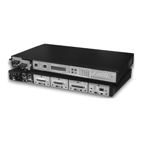
- Page 9 Chapter 1. Introduction The following photo, with graphics, shows the major components which make up the Fiber Multiplexer (with the External Clock and SNMP options installed). This photo shows a unit with E1-BNC card in port 1, X.21 data communications card in port 2, T1-RJ45 card in port 3, and 10/100Base Ethernet bridge in port 4.
-
Page 10: Technical Specifications
Chapter 1. Introduction 1.3 Technical Specifications E1 Link Framing Unframed (transparent*) Bit Rate 2.048 Mb/s Line Code HDB3 Line Impedance Unbalanced 75 ohms (BNC) Balanced 120 ohms (RJ-45) Receiver sensitivity +3 to -12dB (short haul) "Pulse" Amplitude Nominal 2.37V+/-10% for 75 ohms Nominal 3.00V+/-10% for 120 ohms "Zero"... - Page 11 Chapter 1. Introduction Data Port Channels Interface Types V.35 X.21 RS-530/V.36 RS-449 RS-232 Interface Connectors (provided by 1 to 4 header adapter cables) V.35 Interface 34 pin, Female or Male X.21 Interface 15 pin, D-type Female or Male RS-530 Interface 25 pin, D-type Female or Male RS-449 Interface 37 pin, D-type Female or Male...
- Page 12 Chapter 1. Introduction LED Indicators Power 1 Green Power Module 1 active Power 2 Green Power Module 2 active Optical 1 Amber Off = off On = working (ALS is off) On = working & linked (ALS is set Auto) Blinking = working &...
- Page 13 Chapter 1. Introduction Optical Specifications (secondary fiber need not be identical to primary) Standard Types WDM Types* Type Distance (Km) 20(A)* 20(B)* 40(A)* 40(B)* Tx:1310 Tx:1550 Tx:1310 Tx:1550 Wavelength 1310 1310 1310 1310 1550 Rx:1550 Rx:1310 Rx:1550 Rx:1310 (nm) BER** <10 <10 <10...
-
Page 14: E1 Signal Structure
Chapter 1. Introduction 1.4 E1 Signal Structure E1 link line rate The E1 line operates at a nominal rate of 2.048Mb/s. E1 link line coding The basic E1 line signal is coded using either the Alternate Mark Inversion (AMI) or HDB3 rule. -
Page 15: Applications / Capabilities
Chapter 1. Introduction 1.6 Applications / Capabilities In the following example, the Fiber Multiplexer utilizes an optical fiber connection between a pair of units to provide 4, 8, 12 or 16 channels of E1, T1, Datacom, or 1 to 4 channels of Ethernet Bridge between the units. - Page 16 Chapter 1. Introduction This page left blank intentionally. Version 1.2 Apr 2006...
-
Page 17: Introduction
Chapter 2. Port Card Overview 2.1 Introduction This chapter provides a more descriptive over-view of the available 4-Channel Port card options. Detailed specifications are in Chapter 1, while removal and replacement procedures are detailed in Chapter 3. Unit configuration is all covered in Chapter 4. The cards are NOT designed to be "hot"... -
Page 18: Data I/F Module Overview
Chapter 2. Port Card Overview 2.6 4 x Data I/F Module Overview The 4 x Data 4-Channel Port Cards for the Fiber Multiplexer are modular PCAs which slide into the Fiber Multiplexer chassis and provide four completely independent Data (V.35, X.21, RS-530, RS-449, or RS-232) interfaces. - Page 19 Chapter 2. Port Card Overview When the Fiber Multiplexer is ordered with an V35 Port Card option, a 4-CHANNEL V.35 Card and adapter cable are supplied with each MB34 wired according to the following table. Signal MB34 V.35 Direction Description Function PIN# Circuit...
- Page 20 Chapter 2. Port Card Overview When the Fiber Multiplexer is ordered with an RS449 Port Card option, a 4-CHANNEL RS-449 Card and adapter cable are supplied with each DB37 wired according to the following table. SIGNAL DB37 RS-449 Direction DESCRIPTION FUNCTION CIRCUIT Protective...
- Page 21 Chapter 2. Port Card Overview When the Fiber Multiplexer is ordered with an RS530 Port Card option, a 4-CHANNEL RS-530 Card and adapter cable are supplied with each DB25 wired according to the following table. SIGNAL DB25 CIRCUIT DIRECTION DESCRIPTION Function Protective Frame...
- Page 22 Chapter 2. Port Card Overview When the Fiber Multiplexer is ordered with an RS232 Port Card option, a 4-CHANNEL RS-232 Card and adapter cable are supplied with each DB25 wired according to the following table. Signal DB25 Circuit Direction Description Function Protective Chassis ground.
-
Page 23: Ethernet Bridge Module Option
Chapter 2. Port Card Overview 2.7 Ethernet Bridge Module Option When the Fiber Multiplexer is ordered with an ET100 Port Card option, a Single-Channel Bridge Port Card is supplied. Complete bridging functions are provided. BRIDGE FEATURES 10BASE-T/100BASE-TX, Full Duplex or Half Duplex HP Auto-MDIX, detects and corrects crossed cables IEEE 802.3x flow control available Real-time filtering with 256 address tables... - Page 24 Chapter 2. Port Card Overview Duplex: The original specifications for Ethernet did not allow any bi-directional transmissions. The Ethernet operated in a half duplex mode. Modern Ethernet has the ability to operate in Full duplex mode which essentially doubles the throughput from 10Mbps to 20Mbps on 10Base-T or from 100Mbps to 200Mbps on 100Base-TX.
-
Page 25: Chapter 3. Installation
Chapter 3. Installation 3.1 General This chapter explains in detail the requirements and procedures for the installation of the Fiber Multiplexer Standalone/Rack Mount Fiber Optical Multiplexer. 3.2 Site Preparation Install the Fiber Multiplexer within reach of an easily accessible grounded AC outlet. The outlet should be capable of furnishing 90 to 250 VAC (20 to 60 VDC for DC supply). -
Page 26: Electrical Installation
Chapter 3. Installation 3.4 Electrical Installation 3.4.1 Power connection For a model with AC power supply, AC power (90~250VAC) is supplied to the Fiber Multiplexer through a standard IEC 3-prong receptacle, located on the rear of the chassis. For a model with DC power supply, DC –48V (20~60VDC) is connected to the terminal block, observing the proper polarity. -
Page 27: Rear And Front Panel Connectors
Chapter 3. Installation 3.4.2 Rear and Front panel connectors All 4-Channel Port Cards install into the rear of the Fiber Multiplexer. The back plane provides both DC power to the 4-CHANNEL Port interface cards and routes signals from the cards to the multiplexing circuitry. -
Page 28: Removal/Replacement Procedures
Chapter 3. Installation 3.5 Removal/Replacement Procedures 3.5.1 Optical Module Removal / Replacement (Hot Swappable) The optical interfaces are installed into the front of the Fiber Multiplexer. The front plane connectors of the internal mainboard provide both DC power to the optical interface cards and routes signals from the cards to the multiplexing/de-multiplexing circuitry. -
Page 29: Channel Port I/F Module Removal / Replacement
Chapter 3. Installation 3.5.2 Channel Port I/F Module Removal / Replacement ****CAUTION**** All the following removal/replacement procedures must be done with all power sources disconnected. All 4-Channel Port Cards install into the rear of the Fiber Multiplexer. The channel connector for E1/T1 is held by two "thumb" screws. Loosen both thumb screws (use a flat blade screwdriver if they are too tight), then remove the connector adapter by gently pulling straight back. -
Page 30: Top Cover Removal / Replacement For Internal Access
Chapter 3. Installation 3.5.3 Top cover Removal / Replacement for internal access Normally, there is no need to remove the cover of the unit. All interface cards can be removed and replaced without the need to access the internal portion of the Fiber Multiplexer. However, to change any AC or DC power module, add the SNMP and/or External clock feature, or to change the internal firmware, internal access is required and the cover must be removed. -
Page 31: External Clock Feature Removal / Replacement
Chapter 3. Installation 3.5.4 External Clock Feature Removal / Replacement ***CAUTION*** This procedure should only be performed by qualified service personnel. In addition, all power connections must be removed before attempting to open the case. 1. If the unit is installed in a rack, it must be removed. 2. -
Page 32: Snmp Feature Removal / Replacement
Chapter 3. Installation 3.5.5 SNMP Feature Removal / Replacement ***CAUTION*** This procedure should only be performed by qualified service personnel. In addition, all power connections must be removed before attempting to open the case. 1. If the unit is installed in a rack, it must be removed. 2. -
Page 33: Chapter 4. Operation
Chapter 4. Operation 4.1 Introduction This chapter will go into the details of the specific configuration and operation of the Fiber Multiplexer. Broken into two parts, the first part outlines the procedures and functions when using the integral LCD display with push-button menu keys. The second section will outline the operation when using a VT-100 terminal connected to the RS-232 Console port. -
Page 34: Top Level Menus
Chapter 4. Operation 4.2.1 Top Level Menus The following are the 10 top level Menus. Press the right arrow key to select another top level Menu or press ENTER to reach that menu's sub menu. S Y S T E M C O N F I G Set the Ext Clock (if the option is installed), Save User Set, Load Defaults, Load User Set, Modify Password or Logout. - Page 35 Chapter 4. Operation A L A R M R E P O R T Entering this menu allows "Clearing" the alarm history, setting alarm thresholds, displaying alarm history, and setting function of alarm relays. P E R F O R M A N C E D I S P L A Y Entering this menu allows displaying the current internal performance, the nearest internal performance, resetting the nearest or All performance data.
-
Page 36: Menu Table
Chapter 4. Operation 4.2.2 Menu Table The following is a breakdown of the menu system for the Fiber Multiplexer (LCD). Power on self test ADMINISTRATION [Arrow] (login to remote) [ENTER] (enter local configuration) [ESC] Firmware version Local / Remote top menu Menu Item Parameter Settings [display] SYSTEM CONFIG... -
Page 37: Terminal Mode Operation
Chapter 4. Operation 4.3 Terminal Mode Operation A notebook computer has become an invaluable tool of the Systems Engineer. Connection between the computer and the Fiber Multiplexer is very straight forward. The only hardware required is a RJ-45 to DB9F adapter cable (see below for pin out). The Fiber Multiplexer's RS- 232 Console port acts as a DCE to the PC's DTE communications port. -
Page 38: Configuring In Console Mode
Chapter 4. Operation 4.5 Configuring in Console Mode The Fiber Multiplexer Control Port (labeled RS-232 CONSOLE on the front panel) is a console terminal port designed to facilitate setup of all parameters through the use of a standard text based terminal or any terminal emulation program running on a Personal Computer. Make the appropriate connections, start the terminal application, apply power to the Fiber Multiplexer, then press ENTER on the PC keyboard. -
Page 39: Local Or Remote Login
Chapter 4. Operation 4.5.1 Local or Remote Login ******************************************** **** **** **** CONSOLE MODE Ver 2.03 **** **** **** ******************************************** Local Login Remote Login Press the "1" key to immediately enter into the Local Unit Terminal Mode. The main "LOCAL" root menu will be displayed as follows. LOCAL ******************************************** ****... -
Page 40: System Configuration
Chapter 4. Operation Press "1" to enter the System Configuration menu. LOCAL <<< System Parameter >>> External Clock [ OFF ] Save User Setting Load Default Setting Load User Setting Modify Password Alarm Relay Both Please select the item or <ESC> to previous menu. 4.5.3 System Configuration From this menu the item 1, External Clock, may be selected OFF, or if option is installed, it may be selected for E1 PCM, E1 TTL, T1 PCM, T1 TTL or to X'TAL (internal crystal) mode. -
Page 41: System Reset
Chapter 4. Operation The Alarm Relays may be set to activate the "audible" alarm relay only, the "visual" alarm relay only, both the "audio" and "visual" relays, or to disable the relays. After selecting the desired action, press the <ESC> key to exit this menu. 4.5.4 System Reset The "Load Default Setting"... - Page 42 Chapter 4. Operation For an example of turning on Loopback for Channel A, press "A". The following menu is displayed. LOCAL <<< Define Port 1 Parameter >>> Ch A Ch B Ch C Ch D Service Line Code HDB3 HDB3 HDB3 HDB3 Loopback...
- Page 43 Chapter 4. Operation If we <ESC> back to the "Define System" menu we can configure the card in Port 2 by pressing "4". This is an example for the T1 4-channel module (balanced 100 Ohm) LOCAL <<< Define Port 2 Parameter >>> Ch A Ch B Ch C...
- Page 44 Chapter 4. Operation If we <ESC> back to the "Define System" menu we can configure the card in Port 3 by pressing "5". The following will be displayed. Here is the example for the X.21 4-channel data communication module. LOCAL <<<...
-
Page 45: Alarm Threshold Settings
Chapter 4. Operation For this example, choose the Internal Oscillator by pressing item "4". LOCAL <<< Define Port 3 Parameter >>> Ch A Ch B Ch C Ch D Service Rate (Kbps) 2048 2048 2048 2048 Timing Int Osc Trans. Trans. -
Page 46: Setting System Date And Time
Chapter 4. Operation For example to modify the Code Violation threshold, press "1". LOCAL <<< Define Alarm Threshold >>> (Code Violation) [ 255 (Error Seconds) [ 300 Sec. ] SES (Severely Error Seconds)[ 300 Sec. ] UAS (Unavailable Seconds) [ 300 Sec. ] ============================================================ <<<... -
Page 47: Display System Status
Chapter 4. Operation 4.5.9 Display System Status If we escape back out to the root menu, we can select item #1 to display the system status. The display will look similar to the following. <<< FMUX UNIT SYSTEM STATUS >>> 14:27:24 PORT 1 PORT 2... -
Page 48: Performance Display
Chapter 4. Operation The Alarm Buffer can be cleared by pressing the "c" key. Note that each entry in the buffer is "time stamped" with the actual time of occurrence (based on real time clock setting). So it is important to properly set the Date & Time as described previously. 4.5.11 Performance Display Another important diagnostic display is the Performance Monitor display. -
Page 49: Chapter 5. Loop Back Testing 5.1 General
Chapter 5. Loop Back Testing 5.1 General In this chapter we shall explain the functioning of the loop back modes available in the Fiber Multiplexer. The loop back modes available include Local, Remote, and Remote Request Loop Backs for the Optical interface and the secondary Optical interface (if redundant) as well as Local Loop Back, Near End Loop Back, Remote Loop Back, and Request Remote Loop Back for the E1, T1 and Data communication 4-Channel Port Cards. -
Page 50: E1/T1/Datacom 4-Channel Port Card Loop Back
Chapter 5. Loop Back Testing 5.2.2 E1/T1 4-Channel Port Card Loop Back * LLB (T1/E1 local loop back) near end (NE) far end (FE) * NELLB (near end local loop back) near end (NE) far end (FE) * RLB (T1/E1 remote loop back) near end (NE) far end (FE) * RRLB (request T1/E1 remote loop back) -
Page 51: Datacom (Rs-530, V.35, X.21, Rs-449, Rs-232) 4-Channel Port Card Loop Back
Chapter 5. Loop Back Testing 5.2.3 Datacom (RS-530, V.35, X.21, RS-449, RS-232) 4-Channel Port Card Loop Back * LLB (local loop back) near end (NE) far end (FE) * RLB (remote loop back) near end (NE) far end (FE) * V54up (V.54 remote loop back) near end (NE) far end (FE) * V54dn will release the remote loop back... -
Page 52: Datacom (Rs-530, V.35, X.21, Rs-449, Rs-232) 4-Channel Port Card Timing
Chapter 5. Loop Back Testing 5.2.4 Datacom (RS-530, V.35, X.21, RS-449, RS-232) 4-Channel Port Card Timing FMUX is DCE and provides clocks to connected DTEs (Internal Timing) Int Osc Recover Rate = n x 64 where (from optical) n=1 to 32 Rate = n x 64 FMUX is placed between existing DCE and DTE (External Timing) Ext Clk... -
Page 53: Chapter 6. Snmp Operation
Chapter 6. SNMP Operation 6.1 General The Simple Network Management Protocol (SNMP) is one of many protocols in the Internet Protocol (IP) suite. SNMP is the protocol recommended specifically for the exchange of management information between hosts residing on IP networks. Network management allows you to monitor and control network devices remotely using conventional computer network technology. -
Page 54: The Management Information Base
Chapter 6. SNMP Operation 6.3 The Management Information Base The management information base (MIB) includes a collection of managed objects. Managed objects are defined as parameters that can be managed, such as specific information on device configuring or on performance statistics values. The MIB includes the definitions of relevant managed objects (MIB variables) for the specific node. -
Page 55: Snmp Communities
Chapter 6. SNMP Operation Enterprise-specific MIB's are published and distributed by their creators, who are responsible for their contents. The MIB supported by the Fiber Multiplexer SNMP Agent follows RFC 1158 (MIB-II standard). 6.5 SNMP Communities To enable the delimitation of management domains, SNMP uses "communities". Each community is identified by a name, which is an alphanumeric string of up to 255 characters defined by the user. - Page 56 Chapter 6. SNMP Operation Connect a terminal to console port as usual. Next, login to the local unit. ******************************************** **** **** **** CONSOLE MODE Ver 2.03 **** **** **** ******************************************** Local Login Remote Login Press the "1" key to enter into the Local Unit Terminal Mode. The main "LOCAL" root menu will be displayed as follows.
- Page 57 Chapter 6. SNMP Operation Press "9" to enter the SNMP Card Configuration menu. LOCAL <<< SNMP Card Config >>> 1. SNMP Agent Config 2. Manager Config 3. TFTP and Flash 4. Save and Restart Please select the item or <ESC> to previous menu. Under item 1, "SNMP Agent Config", the parameters for the local SNMP agent (the internal SNMP card) can be configured.
-
Page 58: Configure The Snmp Manager
Chapter 6. SNMP Operation 6.7 Configure the SNMP Manager From the SNMP Card Config menu, select item "2", Manager Config. Manager configuration is required to tell the agent (the SNMP card) who has authority to access the SNMP via "Get" commands (read) or "Set"... -
Page 59: Snmp Upgrade Via Tftp
Chapter 6. SNMP Operation 6.9 SNMP Upgrade via TFTP To upgrade the SNMP firmware, configure a TFTP server on your network. Configuring a TFTP server is beyond the scope of this document. Place the upgrade binary file on the server and set the IP address and path of the server in the SNMP agent. - Page 60 Chapter 6. SNMP Operation local_FPGA-Version System Version Ver2.03 (Read Only) local_interface-Card-Type Local MUX [Opti:1 + 1 ] (Read Only) interfaces [Port 1:E1 75] installed [Port 2:T1 ] [Port 3:X.21] [Port 4:LAN-100M/Full] local_Optical-Port local_Optical-1 Optical Port optical-1_Working(0) on/off optical-2_Off(1) local_Optical-2 Optical Port optical-1_Standby(0) on/off optical-2_Off(1)
- Page 61 Chapter 6. SNMP Operation local_p1cha_data- Data channel A data-rate_2048(0) comm_Data-Rate setting, data rate data-rate_64(1) data-rate_128(2) data-rate_192(3) data-rate_256(4) data-rate_320(5) data-rate_384(6) data-rate_448(7) data-rate_512(8) data-rate_576(9) data-rate_640(10) data-rate_704(11) data-rate_768(12) data-rate_832(13) data-rate_896(14) data-rate_960(15) data-rate_1024(16) data-rate_1088(17) data-rate_1152(18) data-rate_1216(19) data-rate_1280(20) data-rate_1344(21) data-rate_1408(22) data-rate_1472(23) data-rate_1536(24) data-rate_1600(25) data-rate_1664(26) data-rate_1728(27) data-rate_1792(28) data-rate_1856(29) data-rate_1920(30)
- Page 62 Chapter 6. SNMP Operation local_p1cha_data- Data channel A cts_On(0) comm_CTS setting, CTS cts_RTS(1) error_LanCard(252) error_WrongType(253) error_Nocard(254) local_p1cha_data- Data channel A led_Off(0) comm_LED-Status setting, LED led_On(1) status led_Blink(2) error_LanCard(252) error_WrongType(253) error_Nocard(254) local_Date_Time local_Date System Date Change from LCD (Read Only) local_Time System Time Change from LCD (Read Only)
- Page 63 Chapter 6. SNMP Operation local_alarm-Threshold ES alarm es_300s(0) (continued) threshold es_600s(1) local_ES es_900s(2) error_LanCard(252) error_WrongType(253) error_Nocard(254) local_SES SES alarm ses_300s(0) threshold ses_600s(1) ses_900s(2) error_LanCard(252) error_WrongType(253) error_Nocard(254) local_UAS UAS alarm uas_300s(0) threshold uas_600s(1) uas_900s(2) error_LanCard(252) error_WrongType(253) error_Nocard(254) (end of local branch) remote_System (identical to local branch) Version 1.2 Apr 2006...
-
Page 64: Snmp Trap Messages
Chapter 6. SNMP Operation 6.11 SNMP Trap Messages Trap messages: Alarm Buffer Empty Optical 1 Signal Loss ON Port 4-Ch A Loopback ON Power Turn On Optical 1 Signal Loss OFF Port 4-Ch A Loopback OFF Power 1 Fail Optical 2 Signal Loss ON Port 4-Ch B Loopback ON Power 2 Fail Optical 2 Signal Loss OFF... - Page 69 Technical Inquiry Form MODEL No.: FMUX01A Please fill in the configuration settings with ' ' marks into the following table. Send it to us by fax, and we will reply to you immediately. Firmware Version: _____________________ FPGA Version: ____________________ (Press the ESC key from the 'SYSTEM CONFIG' display on the LCD.) Installed Options (if any) External Clock Card SNMP Card...
- Page 72 E1/T1 DSU/CSU Series Fiber Converter Series CTC Union Technologies Co., Ltd. Far Eastern Vienna Technology Center (Neihu Technology Park) 8F, No.60, Zhouzi Street Neihu, Taipei, Taiwan Phone:(886) 2.2659.1021 Fax:(886) 2.2799.1355 E-mail: info@ctcu.com http://www.ctcu.com...
Need help?
Do you have a question about the FMUX-01A and is the answer not in the manual?
Questions and answers