Neptronic SKG3 Series Installation Instructions Manual
Gas fired humidifier
Hide thumbs
Also See for SKG3 Series:
- Installation instructions manual (50 pages) ,
- Installation instructions manual (56 pages)
Table of Contents
Advertisement
Quick Links
Gas Fired Humidifier
SKG3 Series
INSTALLATION INSTRUCTIONS
Read and save these instructions
WARNING: Risk of fire or explosion. May
cause property damage, personal injury or loss
of life. Please follow installation instructions
carefully.
FOR YOUR SAFETY: Do not store or use
gasoline or other flammable vapors and liquids
in the vicinity of this appliance.
WHAT TO DO IF YOU SMELL GAS:
Do not try to light any appliance.
Do not touch any electrical switch,
and do not use telephones in your
building.
Immediately call your gas supplier from
an off-site telephone.
Follow the gas supplier's instructions.
If you cannot reach your gas supplier,
call the fire department.
WARNING: Risk of injury or property damage.
Installation and service must be performed by a
qualified installer, service agency, or the gas
supplier.
SKG3-IOM – Rev.: 131024
Advertisement
Table of Contents

Related Manuals for Neptronic SKG3 Series


Summary of Contents for Neptronic SKG3 Series
-
Page 1: Installation Instructions
Gas Fired Humidifier SKG3 Series INSTALLATION INSTRUCTIONS WARNING: Risk of fire or explosion. May cause property damage, personal injury or loss of life. Please follow installation instructions carefully. FOR YOUR SAFETY: Do not store or use gasoline or other flammable vapors and liquids in the vicinity of this appliance. -
Page 3: Safety
ACCESS TO LIVE ELECTRICAL PARTS MAY BE GAINED – ALWAYS STORE KEYS CENTRALLY WITH NOMINATED RESPONSIBLE PERSON. Neptronic® systems are designed to be used with mains, reverse osmosis, WATER demineralized or partially softened water. On no account attempt to introduce any other fluid or chemical into the system without first consulting NEP or its authorized distributor. -
Page 4: Foreword
Foreword This installation and operation manual has been developed to facilitate the installation and the operation of the SKG3 series gas fired steam humidifier. The strict application of these instructions will ensure the conformity of the installation and operation to the manufacturer's recommendations. -
Page 5: Table Of Contents
SKG3 Steam Humidifier Table of content Safety ..............................1 Foreword ............................... 2 Table of content ........................... 3 Technical Specifications ........................4 Dimensions & Weights ........................5 Installation Overview ......................... 10 Stage 1 – Unit Positioning and Mounting ..................11 Stage 2 – Steam Distribution Installation ..................13 Stage 3 –... -
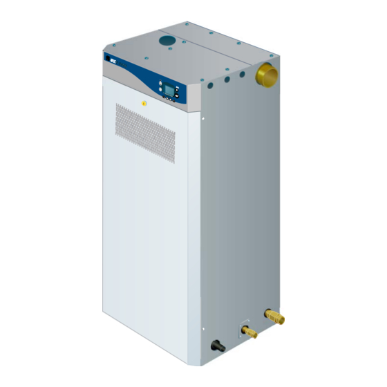
Page 6: Technical Specifications
SKG3 Steam Humidifier Technical Specifications Steam Outlet LCD display & control panel Flue outlet (either side*) Water level sight glass Gas supply inlet (either side*) S/S 316 Combustion chamber & heat exchanger S/S 316 Evaporation chamber Water supply (either side*) Drain outlet (either side*) Front door... -
Page 7: Dimensions & Weights
SKG3 Steam Humidifier Dimensions & Weights General dimensions - Fig. 2 General Dimensions & weight & Steam Outlets detail Weight No of Steam Dimensions in inches [mm] Lb (Kg) Nb of Model Steam Outlet module Full of Outlets Diam. Empty water SKG3-110-1 N/P Ø3”... - Page 8 SKG3 Steam Humidifier Dimensions & Weights Position & Dimension of connections C=22'’ (560) 14½’’ (370) 10½’’ (270) Electrical 5'’ (127) control Power supply 2'’ (51) Flue 49½’’ supply (1257) Front door 43½’’ A=54'’ (1105) (1372) Main Drain 17'’ (436) drain 15'’...
- Page 9 SKG3 Steam Humidifier Dimensions & Weights Option - Ducted combustion air inlet dimension 6'’(150) Ducted combustion air dimensions - Fig. 4 dimensions in bracket are in mm Dimensions in inches [mm] No of No of Model modules inlet inlet Diam. SKG3-110-1 N/P Ø2’’...
- Page 10 SKG3 Steam Humidifier Dimensions & Weights Option - Weather proof enclosure general dimension and weight Weather proof enclos. 4 modules configuration - Fig. 6 Weather proof enclos.1 to 3 modules configuration - Fig. 5 63-5/8" 6-7/8'’ (1616) STEAM OUTLET STEAM OUTLET (X2) (174) FLUE TERMINAL...
- Page 11 Caution should be exercised to ensure balanced load before lifting. Lifting of SKG3 Steam Humidifier MUST ALWAYS be done using the appropriate Neptronic Lifting Bracket (sold separately). Lifting sling angle should be greater than 30˚ to the horizontal. Optional weather proof enclosure is provided with four (4) lifting eyelets located at each corner on the top of the enclosure, see fig.
-
Page 12: Installation Overview
SKG3 Steam Humidifier Installation Overview All installation work must comply with local regulations. All work related to the installation of the SKG3 Steam Humidifier MUST only be performed by skilled and qualified technical personnel (e.g. qualified gas installer, fitters, electricians, plumbers or technicians with appropriate training). The customer is responsible for ensuring their suitability. -
Page 13: Stage 1 - Unit Positioning And Mounting
SKG3 Steam Humidifier Stage 1 – Unit Positioning and Mounting Safety Any installation work MUST be carried out by suitably qualified personnel. considerations The following considerations should be taken into account before deciding on the location for the SKG3 Steam Humidifier: ... - Page 14 SKG3 Steam Humidifier Stage 1 – Unit Positioning and Mounting 20'’ (510) minimum 24'’ (600) minimum 24'’ (600) minimum 30'’ (800) minimum Standard enclosure clearance - Fig. 12 dimensions in bracket are in mm Weather proof enclosure clearance - Fig. 13 dimensions in bracket are in mm Minimum clearances are : Minimum...
-
Page 15: Stage 2 - Steam Distribution Installation
4 ¼’’ (108mm) up to 528lb/h (240kg/h) 5 ¼’’ (133mm) up to 560lb/h (255kg/h) All Humidifier below 220lb/h (100kg/h) capacity should use standard Neptronic® SAMB E2 Steam distribution pipes, Multi-Steam can be offered if shorter absorption distances are required. - Page 16 SKG3 Steam Humidifier Stage 2 – Steam Distribution Installation Steam outlet configuration for weather proof Integrated steam manifold enclosure Steam outlet Weather proof enclosure single steam outlet - Fig. 17 SKG3 humidifier with weather proof enclosure is provided with an integrated steam manifold with outlet on one or other side of the humidifier.
- Page 17 SKG3 Steam Humidifier Stage 2 – Steam Distribution Installation The minimum steam manifold length that can be used with the SKG3-110-1 to Selection of SKG3-210-1 is 35’’ (900mm). Any manifold below this dimension will have steam insufficient outlet spigots to allow proper steam distribution. distribution If duct size is below 35’’...
- Page 18 SKG3 Steam Humidifier Stage 2 – Steam Distribution Installation Steam pipe work to Duct connections (SKG3-110 to 210) Insulated pipe SKG3-110 Air Duct Min. 2/5 H Min. 7° pipe slope Ø3'’ (76) Min. 4'’ (100) Static pressure + 2'’ (50) ؽ'’...
- Page 19 SKG3 Steam Humidifier Stage 2 – Steam Distribution Installation Selection of For all Multi-Steam units use the Neptronic® Humidisoft program to size the Multi-Steam unit. Where two Multi-Steam units are required, duties in excess of 528lb/h (240kg/h) make your selection using the following rules: ...
- Page 20 SKG3 Steam Humidifier Stage 2 – Steam Distribution Installation Steam pipe work to Duct connections (SKG3-110 to 810) Air duct SKG3-110 to 265 Insulated pipe Min. 7° pipe slop Ø3'’ (76) Multisteam Static pressure + 2'’ (50) ؽ'’ (15) Total length of steam conduit should not exceed 17' (5m) Steam pipe work 1 module, Multisteam - Fig.
- Page 21 SKG3 Steam Humidifier Stage 2 – Steam Distribution Installation Air Duct SKG3-505 to 610 Min. 7° pipe slope Insulated pipe Ø5 ¼'’ (133) Ø3'’ (76) (x3) ؽ'’ (15) Static pressure + 2'’ (50) ؾ'’ (22) Steam pipe work 3 modules - Fig. 28 dimensions in bracket are in mm Three Ø3’’...
-
Page 22: Stage 3 - Gas Supply Connection
SKG3 Steam Humidifier Stage 3 – Gas Supply Connection CAUTION : Gas piping installation MUST comply with all local codes and regulations, and current ANSI Z223.1, ‘’National Fuel Gas Code’’ or CAN/CSA-B149. Gas pressure to the Humidifier MUST never exceed 26’’ w.c. (6kPa). A manual shut off valve (not supplied) MUST be installed on the Gas supply line to the Humidifier. -
Page 23: Stage 4 - Water Supply Installation
Water supply installation should conform to local codes and regulations. Any installation work must be carried out by suitably qualified personnel. Water inlet Neptronic® SKG3 Humidifier is designed to be used with mains, reverse Specifications osmosis, de-ionized and de-mineralized water. -
Page 24: Stage 5 - Water Drain Connection
SKG3 Steam Humidifier Stage 5 – Water Drain Connection Water Drain installation should conform to local codes and regulations. Any installation work must be carried out by suitably qualified personnel. Water Drain Water Drain temperature: 140˚F (+60˚C) Specification Main Drain Outlet Pan Drain outlet Model Connection size... -
Page 25: Stage 6 -Combustion Air Installation
SKG3 Steam Humidifier Stage 6 –Combustion Air Installation CAUTION : Combustion and room ventilation air should conform to local codes and regulations and to section 7.2, 7.3 or 7.4, Air for Combustion and Ventilation of the current ANSI Z223.1 ‘’National Fuel Gas Code’’ or CAN/CSA-B149. CAUTION : Air for combustion MUST NOT be contaminated by halogens, ammonia, bromides, chlorides, fluorides, iodides or dust. - Page 26 SKG3 Steam Humidifier Stage 6 –Combustion Air Installation Natural Ventilation Installation High level opening Outside Wall Low level opening Humidifier’s Air openings Natural ventilation configuration - Fig. 34 Ducted Combustion Air “Ducted Combustion Air” option, also called “Sealed Combustion”, is available upon request.
- Page 27 SKG3 Steam Humidifier Stage 6 –Combustion Air Installation Ducted Combustion Air Single Humidifier Ø 2'’ (51) minimum SKG3-110 to 210 Humidifier inlet Ø 2'’ (51) Ducted combustion air 1 module - Fig. 35 dimensions in bracket are in mm 2 Modules Humidifier 1 to 2 outlet manifold SKG3-265 to 405...
- Page 28 SKG3 Steam Humidifier Stage 6 –Combustion Air Installation 3 Modules 1 to 3 outlets manifold Ø 6'’ (150) minimum Humidifier SKG3-505 to 610 Ø 2'’ (51) minimum Humidifier inlet Ø 2'’ (51) Ducted combustion air - Fig. 37 dimensions in bracket are in mm 4 Modules Humidifier 1 to 4 outlets manifold...
-
Page 29: Stage 7 -Flue Gas Venting Connection
Flexmaster Z-Flex Model SVE Series III rigid venting system, Magnaflex PV Model insulated flexible vent venting system. Flue Gas Venting Neptronic® SKG3 Steam Humidifier is a fan assisted non condensing positive pressure flue gas appliance. Specification Maximum flue gas temperature: Ambient 390˚F ( 217˚C). - Page 30 SKG3 Steam Humidifier Stage 7 –Flue Gas Venting Connection Minimum spacing When Flue gas terminal is located at outside air. Minimum spacing Building or other element (in) [mm] Below adjacent opening (window, air vent or any 12 [300] other ventilation opening) 3 [75] Below a gutter, drain or soil pipe 8 [200]...
-
Page 31: Stage 8 -Electrical Supply And Installation
SKG3 Steam Humidifier Stage 8 –Electrical Supply and Installation Electrical Power The SKG3 Steam Humidifier requires a 120, 208 or 240V single phase supply. Supply Weatherproof Standard Model Voltage (V) enclosure Current (A) option (A) 120 – 1ph SKG3 208 – 1ph 110, 155, 180, 210 240 –... -
Page 32: Stage 9 -Electrical Control Connections
SKG3 Steam Humidifier Stage 9 –Electrical Control Connections Electrical Control Neptronic® SKG3 Steam Humidifier has a modulating control system and requires Connections an analogue control signal. All controls connections have been grouped on a specific Interface P.C.B. RS-232 Connection RS-485 Connection... - Page 33 SKG3 Steam Humidifier Stage 9 –Electrical Control Connections Humidifier Neptronic® SKG3 modulating Steam Humidifier can be installed in conjunction with Control with Neptronic® HRO20 humidity controller. humidity controller To be wired if you intend to control Humidifier from HRO20 (Mode External in Control Setup menu - Display #200)
- Page 34 Neptronic® SKGE3 modulating Steam Humidifier can be installed in conjunction with a VAV system, in this case Neptronic® SHC80 Duct humidity sensor placed in the supply Air will act as a Hi level Duct Humidity sensor. Humidity will be controlled by Neptronic®...
-
Page 35: Stage 9 -Bacnet ® Interface Set-Up
SKG3 Steam Humidifier Stage 9 –BACnet interface set-up ® Important note ® This page describes the BACnet interface set up. ® ‘ ’BACnet interface’’ option is available only upon request. Dip switch Pull Up enable adjustment for RS-232 120 Ohm terminaison (last node) enable RS-485 ANLG OUT RS-485 Connection... -
Page 36: Initial Verification
SKG3 Steam Humidifier Initial verification Initial verification and start up – commissioning – should be carried out by suitable qualified personnel. 1. Ensure that the humidifier cabinet is installed in a location where the Clearance humidifier can be serviced correctly. 2. - Page 37 SKG3 Steam Humidifier Start-Up Proceed to start-up the Humidifier, as follows: Open the front access door of the humidifier cabinet; make sure that manual drain valve is closed. Start up the humidifier by pushing (ON/OFF) button located on the humidifier control panel.
-
Page 38: Commissioning - Operation Description
SKG3 Steam Humidifier Commissioning – Operation description Control Panel Control panel of Neptronic® SKG3 Steam humidifier is equipped with a user friendly LCD display and extensive access to status, alarms, and set-up menus. Description Blue Power ON LED Red ALARM LED... -
Page 39: Operation Display
SKG3 Steam Humidifier Operation display During normal operation the following display will indicate main information about the Operation scrolling system: messages on display DEMAND: 100% OUTPUT: 100% ROOM HUMIDITY 30%RH Scrolled message Description Current room set point in % RH. ROOM SETPOINT Current room humidity reading in % RH. -
Page 40: Status Menu
SKG3 Steam Humidifier Status Menu Display Description STATUS Room relative Humidity: Room Rel. Humidity Displays the Room Relative Humidity if a room humidistat is connected to the 64%RH humidifier. STATUS System demand: System Demand Displays the humidity demand from the system. 64,3% 100% represent a full demand. -
Page 41: Control Set Up Menu
SKG3 Steam Humidifier Control Set Up Menu Display Description Values External Control Mode: CONTROL SETUP Selection of Control mode. Internal Control Mode Com Port If External is selected, the control demand will be received INTERNAL by the analog input; if Com Port is selected, the control demand will be received by the communication port (BACnet option). - Page 42 Tank Operation: CONTROL SETUP Selection of Tank operation, when SKG Humidifier has Parallel Tank Operation more than one module. SEQUENTIAL For optimum control Neptronic® recommends sequential operation. CONTROL SETUP Percentage Lock On Capacity: Lock On Capacity Selection of Humidifier Capacity reduction...
-
Page 43: System Set Up Menu
SKG3 Steam Humidifier System Set Up Menu Display Description Values SYSTEM SETUP From 400 to 3000 Hrs Service Timer: Service Timer Selection of delay between Service alarms. Increment: 100 Hrs 1000 Hrs Value is indicated in Hours. Default:1000 Hrs SYSTEM SETUP From 1 to 24 Hrs Auto drain Delay: Auto Drain Delay... - Page 44 SKG3 Steam Humidifier System Set Up Menu Display Description Values SYSTEM SETUP From 140 to 180 Liquid Crystal Display Contrast: Lcd Contrast Selection of LCD Display Contrast. Increment: 1 Value is indicated in relative number. Default: 160 SYSTEM SETUP Language Selection: English or Français Language Selection Selection of Language displayed by interactive menus.
-
Page 45: Alarms Menu
SKG3 Steam Humidifier Alarms Menu Display Description Operation Period: Displays the running hours countdown, it displays the reverse number of hours of Display # 107. ALARMS IMPORTANT: Operation Period H1: 1000Hr This countdown should be reset after servicing in order to remove alarm for call of H2: 800Hr service. -
Page 46: List Of Alarms
SKG3 Steam Humidifier List of Alarms No alarm should be reset prior to identifying and rectifying the cause of the fault. Please refer to the troubleshooting guide for help to identify and resolve potential problems. When an alarm is indicated by the LCD display, the Red LED Alarm will flash. Normal operation of the humidifier is altered. -
Page 47: Diagnostics Menu
SKG3 Steam Humidifier Diagnostics Menu Display Description Input Voltage: Displays the analog inputs: DIAGNOSTICS Input #1: Control set point input voltage Input Voltage Input #2: Room humidity input voltage Input #1: 7.15V Input #2: 7.13V Input #3: Duct humidity input voltage. Input #3: 7.14V Value indicated is in Volt. -
Page 48: Com Port Set Up Menu
SKG3 Steam Humidifier Com port set up Menu Display Description Values COM PORT SET UP Com Port Speed: Com Port Speed N/A Baud Default: N/A N/A Baud Not Applicable, communication speed unit is not a variable. The communication speed is expressed in Baud. MS/TP MAC Address Selection of MS/TP MAC address COM PORT SET UP... -
Page 49: Personal Notes
SKG3 Steam Humidifier Personal notes... -
Page 50: Exploded Views & Parts List
SKG3 Steam Humidifier Exploded views & Parts list General General exploded view - Fig. 50 Item Description Model Part number SKG Cabinet All models SW G1012 Evaporation chamber assembly See detail Front door assembly See detail Master (1 ) module SP G1002-21 Front Panel Slave module... - Page 51 SKG3 Steam Humidifier Exploded views & Parts list Item 2 – Evaporation chamber assembly detail Evaporation chamber exploded view - Fig. 51 Item Description Model Part number Water tank All models SW G3208 Water tank gasket All models SP G2101 Band clamp All models SP G3150-M...
- Page 52 SKG3 Steam Humidifier Exploded views & Parts list Item 3 - Door assembly detail Door assembly detail - Fig. 52 Item Description Model Part number Front door All models SP G1012-5 Air filter All models SP G4202 Air filter holder All models SP G1012-27 Spring washer...
- Page 53 SKG3 Steam Humidifier Exploded views & Parts list Item 11 – Igniter assembly Igniter assembly - Fig. 54 Item Description Model Part number Igniter holder assembly All models SW GIGNHOLD-ASSY 120V SW GIGNITER-120 Igniter 208 or 240V SW GIGNITER-230 Item 11 – Internal flue pipe (SKGE3-2503 to 4004) Flue pipe assembly - Fig.
- Page 54 SKG3 Steam Humidifier Exploded views & Parts list Water level sensor assembly Water level sensor assembly - Fig. 56 Item Description Model Part number Water level sensor assembly All models SW GWATLEV-ASSY Water level sensor All models SW GWATLEV-SUB...
-
Page 55: Multiple Modules Composition Table
SKG3 Steam Humidifier Multiple modules composition table Module Module Module Module 1 (master) Module description - Fig.57 Module model number & quantity Humidifier No of SKG100 SKG150 SKG180 SKG200 Model Modules SKG3-110-1 N/P SKG3-155-1 N/P SKG3-180-1 N/P SKG3-210-1 N/P SKG3-265-2 N/P SKG3-310-2 N/P SKG3-350-2 N/P SKG3-405-2 N/P... -
Page 56: General Conditions Of Sales & Warranty
SKG3 Steam Humidifier General conditions of sales & warranty General 10. Return of good Unless otherwise arranged, in writing, the acceptance Goods received by the purchaser cannot be returned of the Order Confirmation by the purchaser includes unless a completed "R.M.A. Form" (Return Material acceptance of the "General Conditions of Sale and Authorization Form) has been issued by NEP's Customer Warranty"... - Page 58 Neptronic® Head office: 400 Blvd Lebeau, Montreal, Qc, H4N 1R6, CANADA Tel.: (1) 514 333-1433 Fax: (1) 514 333-3163 Customer service Fax: (1) 514 333-1091 Toll free: 1 800 361-2308 Business hours: from Monday to Friday, 8:00am to 5:00pm (Eastern Time) US Office: NEP Inc.
Need help?
Do you have a question about the SKG3 Series and is the answer not in the manual?
Questions and answers