
Related Manuals for Neptronic SKG4-N1101


Summary of Contents for Neptronic SKG4-N1101
- Page 1 Gas Fired Humidifier SKG4-N Series Installation Instructions and User Manual READ AND SAVE THESE INSTRUCTIONS 4011008 SKG4-N-ESL-181116...
- Page 2 Health and Safety Neptronic has considered the aspects of the design of their humidification systems to reduce as much as possible the risk of Legionnaires’ disease and other similar conditions, but it is important that users are also aware of their responsibilities under Health and Safety regulations in reducing the risk of legionellosis.
- Page 3 Always store keys centrally with a nominated responsible person. Water Neptronic systems are designed to be used with tap, reverse osmosis or deionized water. On no account must any other fluids or chemicals be introduced into the system without first consulting Neptronic or its authorized distributor.
- Page 4 Neptronic. Correct Use Neptronic systems and its products are designed only for humidification use. Any other application is not considered appropriate for the intended purpose. The manufacturer cannot be made liable for any damage resulting from incorrect use.
-
Page 5: Table Of Contents
Stage 4 - Water Supply Installation ............................29 Water Inlet Specifications ..............................29 Water Supply Line Installation ............................. 29 Stage 5 - Water Drain Connection ............................30 Water Drain Specifications ..............................30 Water Drain Installation................................ 30 www.neptronic.com Page | - 4 -... - Page 6 Cleaning the Humidifier................................ 62 Chamber Removal - Humidifier with OSHPD Preapproval (OSP) ..................64 Inspecting the Humidifier Components ..........................65 Burner Assembly and Heat Exchanger Tube Maintenance....................66 Burner Maintenance................................66 Troubleshooting ..................................67 www.neptronic.com Page | - 5 -...
-
Page 7: Overview
Refer to the Dimensions and Weight table in the Standard Humidifier Unit section for system dry weights. 4 lifting eyelets Illustration 1 - Lifting (Weather Proof Enclosure) Unpacking The SKG4 humidifier is shipped in a wooden crate. Ensure packing wooden crate and skid is removed prior to commissioning. www.neptronic.com Page | - 6 -... -
Page 8: List Of Accessories Supplied
[100] Note 1: Maximum static duct pressure is 5” w.c. (1.25 kPa). For higher static duct pressures, consult Neptronic or its authorized distributor. Note 2: Standard humidifier is designed for natural ventilation combustion air. “Ducted Combustion Air” option is available upon request. See Stage 6 of installation procedure for more details. -
Page 9: Visual Overview
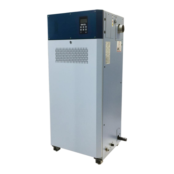
Front door and heat exchanger Gas supply inlet (either side) Water supply (either side) Drain outlet (either side) Quick connect water outlet 316SS Evaporation chamber (shown in “DOWN” position) Illustration 2 - Humidifier Overview www.neptronic.com Page | - 8 -... -
Page 10: Standard Humidifier Unit
Table 2 - Dimensions and Weight (Standard Humidifier) Weight Steam Outlet Dimensions (in) [mm] (lb) [kg] No. of Model Modules Dia. Full of Empty (in) [mm] Water SKG4-N1101 N/P SKG4-N1551 N/P Ø76 SKG4-N1801 N/P [1372] [610] [560] [280] [470] [145] [200] SKG4-N2101 N/P SKG4-N2652 N/P SKG4-N3102 N/P Ø76... -
Page 11: Position And Dimension Of Connections
Dimensions (in) [mm] No. of Model Drain Outlet Pan Drain Water Inlet Gas Inlet Flue Outlet Modules Diameter Diameter Diameter Diameter Diameter SKG4-N1101 N/P SKG4-N1551 N/P Ø3/4 Ø1/2 Ø1/2 Ø1 Ø3 SKG4-N1801 N/P [20] [15] [15] [25] [76] SKG4-N2101 N/P... -
Page 12: Option - Ducted Combustion Air Inlet Dimensions
Illustration 5 - Ducted Combustion Air Inlet Dimensions Table 4 - Dimensions and Weight (Ducted Combustion) Air Inlet Dimensions (in) [mm] No. of No. of Air Model Dia. Modules Inlet(s) (in)[mm] SKG4-N1101 N/P SKG4-N1551 N/P Ø2 17.6 13.8 SKG4-N1801 N/P [51] [448] [352] SKG4-N2101 N/P SKG4-N2652 N/P SKG4-N3102 N/P Ø2... -
Page 13: Weather Proof Enclosure
Illustration 6 - Weather Proof Enclosure Table 5 - Dimensions and Weight (Weather Proof Enclosure) Dimensions (in) [mm] Weight (lb) [kg] No. of Model Full of Modules Empty Water SKG4-N1101 N/P SKG4-N1551 N/P 74.7 30.6 33.25 SKG4-N1801 N/P [1898] [778] [845] [736]... -
Page 14: Multiple Module Composition
Illustration 7 - Multiple Module Humidifier Table 6 - Multiple Module Composition No. of Module Model Number and Quantity Model Modules SKG100 SKG150 SKG180 SKG200 SKG4-N1101 N/P SKG4-N1551 N/P SKG4-N1801 N/P SKG4-N2101 N/P SKG4-N2652 N/P SKG4-N3102 N/P SKG4-N3502 N/P SKG4-N4052 N/P SKG4-N5053 N/P SKG4-N5603 N/P... -
Page 15: Installation Overview
Stage 8: Electrical Supply and Installation Stage 9: Electrical Control Connections Stage 2 Stage 7 Stage 6 Stage 8 Stage 9 Stage 3 Stage 1 Stage 5 Stage 4 Illustration 8 - Installation Overview www.neptronic.com Page | - 14 -... -
Page 16: Stage 1 - Unit Positioning And Mounting
Provide a level, solid foundation for the humidifier. Ensure that the floor beneath the humidifier is water proof to withstand any water spillage during servicing or in the event of a problem. www.neptronic.com Page | - 15 -... -
Page 17: Ambient Condition And Altitude
Leave a clearance of at least 30” (0.8 m) to the front panel and 24” (0.6 m) on the left and right sides of the humidifier. Leave a clearance of at least 20” (0.5 m) on top of the humidifier. Illustration 9 - Standard Enclosure Clearances www.neptronic.com Page | - 16 -... -
Page 18: Minimum Clearances - Weather Proof Enclosure
Leave a clearance of at least 30” (0.8 m) to the front panel and 24” (0.6 m) on the left and right sides of the humidifier. Leave a clearance of at least 20” (0.5 m) on top of the humidifier. Illustration 10 - Weather Proof Enclosure Clearances www.neptronic.com Page | - 17 -... -
Page 19: Weather Proof Enclosure Installation On Floor/Roof
The base of the weather proof enclosure is provided with holes of ½” (12mm) diameter to secure the SKG4 humidifier to the roof curb, with the use of bolts and washers of ½” (12mm) diameter (not supplied). www.neptronic.com Page | - 18 -... -
Page 20: Stage 2 - Steam Distribution Installation
Single module humidifier with 2 S.A.M.E2 manifolds Single module humidifier Min. 7° with Multi-Steam. Min. 7° Static pressure + 2" (50mm) Static pressure + 2" (50mm) Illustration 14 - Steam Distribution Pipes: Correct Installation www.neptronic.com Page | - 19 -... -
Page 21: Weather Proof Enclosure Steam Outlets
Steam Outlet Dimension and Quantity - Weather Proof Enclosure Table 8 - Steam Outlet Dimensions and Quantity (Weather Proof Enclosure) Steam Outlet Steam Outlet Model Quantity Diameter Ø3” SKG4-N1101 to 2101 (76mm) Ø4” SKG4-N2652 to 4052 (100mm) Ø5” SKG4-N5053 to 6103 (125mm) Ø4”... -
Page 22: Steam Dispersion General Recommendations
Selection of Steam Distribution Manifolds The minimum steam manifold length that can be used with the models SKG4-N1101 to SKG4-N2101 is 3 feet (900mm). Any manifold below this dimension will have insufficient outlet spigots to allow proper steam distribution. - Page 23 Placement of Steam Pipe in Vertical Duct 2 Pipes 3 Pipes 24’’ minimum 36’’ minimum (900mm) (600mm) 1/4 W 1/2 W 1/4 W 1/6 W 1/6 W 1/3 W 1/3 W Illustration 18 - Pipe Placement: Vertical Duct www.neptronic.com Page | - 22 -...
-
Page 24: Steam Pipe Work To Duct Connections With S.a.m.e2
= 35" (900mm) Total length of steam conduit must not exceed 16ft (5m) Illustration 19 - S.A.M.E2 Steam Pipe Work (SKG4-N1101) A single Ø3” (76mm) feed pipe must be connected to two S.A.M.E2 steam manifolds with a suitable reduction at the lowest point to allow a ؽ”... -
Page 25: Multi-Steam System
Multi-Steam System Selection of Multi-Steam System For all Multi-Steam units, use the Neptronic Humidisoft program to size the unit. Where two Multi-Steam units are required (duties in excess of 660lb/hr (300kg/h)), make your selection using the following rules: o Divide the air volume flow in half. -
Page 26: Steam Pipe Work To Duct Connections With Multi-Steam
Total length of steam conduit must not exceed 16ft (5m). Illustration 23 - Steam Pipe Work Multi-Steam (SKG4-N1101 to 2651) A single Ø3” (76mm) feed pipe must be connected to a single Multi-Steam with a suitable reduction at the lowest point to allow a ؽ”... - Page 27 ؽ” (15mm) condensate drain from the main steam supply. This must be reproduced two times. If the two ؽ” (15mm) condensate pipes are connected, the common condensate drain must be ؾ” (20mm). www.neptronic.com Page | - 26 -...
-
Page 28: Stage 3 - Gas Supply Connection
After installation, field piping and humidifier gas train must be checked for leaks. Do not use soap solution or open flame on the humidifier gas train. A gas leak detector must be used. All leaks must be sealed prior to commissioning the humidifier. www.neptronic.com Page | - 27 -... -
Page 29: Gas Pipe Diameter
Table 9 - Gas Connection Size Model Gas Connection Size Ø1” (25mm) Male SKG4-N1101 to 4052 Ø1 ½” (40mm) Male SKG4-N5053 to 8104 Refer to local codes and regulations regarding the type and volume of gas handled, in order to obtain the pressure drop allowed in the gas line and determine the gas pipe diameter. -
Page 30: Stage 4 - Water Supply Installation
For normal operation, pre-treatment of water is not necessary. As the humidifier is equipped with the Neptronic Anti-Foaming Energy Conservation (AFEC) system, which drains the humidifier in the presence of foam to ensure clean and safe operation, the use of softened water is not recommended. -
Page 31: Stage 5 - Water Drain Connection
Water drain temperature: 140˚F (60˚C) Water Drain Outlet Pan Drain Outlet Open Drain Model Connection Size Connection Size Minimum size SKG4-N1101 to 2101 Ø⅞” (22mm) Ø3” (80mm) Ø1 ⅜” (36mm) ؽ” (15mm) SKG4-N2652 to 4052 Ø2” (50mm) SKG4-N5053 to 8104 Ø4”... -
Page 32: Pan Drain Connection On Weather Proof Enclosure
During normal operation, the humidifier reduces drain water temperature to 140˚F (60°C). CAUTION: During a power failure, the drain water temperature is not reduced. Installed drain piping must be rated to 212°F (100°C). www.neptronic.com Page | - 31 -... -
Page 33: Stage 6 - Combustion Air Installation
The SKG4 humidifier has filtered air openings through the front door. Do not block or obstruct the humidifier air openings. The humidifier is factory adjusted for correct performance. Do not alter throttle setting or restrict blower combustion air inlet. www.neptronic.com Page | - 32 -... -
Page 34: Combustion Air Specification - Natural Ventilation
Natural Ventilation Installation Number of Model Minimum Low Level Minimum High Level Modules Opening – Inlet (in Opening – Outlet (in ) [cm ) [cm SKG4-N1101 N/P [240] [240] SKG4-N1551 N/P [360] [360] SKG4-N1801 N/P [420] [420] SKG4-N2101 N/P [480]... -
Page 35: Natural Ventilation Installation
Ensure that the combustion air duct connections are air tight. The minimum combustion air duct upward gradient must be ¾” (20mm) in 40” (1000mm) horizontal run. Combustion Air Inlet Model Diameter per Module Ø2” (51mm) O.D. SKG4-NXXXX www.neptronic.com Page | - 34 -... - Page 36 SKG4-N Gas Fired Humidifier Installation Instructions and User Manual Single Module Humidifiers: SKG4-N1101 to SKG4-N2101 Ø2" (51mm) minimum Humidifier inlet Ø2" (51mm) Illustration 33 - Ducted Combustion Air (1 Module) 2 Module Humidifiers: SKG4-N2652 to SKG4-N4052 1 to 2 Outlet manifold Ø4"...
- Page 37 Illustration 35 - Ducted Combustion Air (3 Modules) 4 Module Humidifiers: SKG4-N7104 to SKG4-N8104 1 to 4 Outlet manifold Ø8" (205mm) minimum Ø2" (51mm) minimum Humidifier inlet Ø2" (51mm) Illustration 36 - Ducted Combustion Air (4 Modules) www.neptronic.com Page | - 36 -...
-
Page 38: Stage 7 - Flue Gas Venting Connection
Flexmaster Z-Vent Model SVE Series III rigid venting system. DuraVent FasNSeal (single-wall) or FasNSeal W2 (double-wall) venting system. MagnaFlex PV Model insulated flexible venting system. Selkirk/HeatFab Saf-T Vent Model single-wall or double-wall venting system. www.neptronic.com Page | - 37 -... -
Page 39: Flue Gas Venting Specification
100ft (30m) - 10ft (3m) x (total number of 90˚elbow) - 5ft (1.5m) x (total number of 45˚elbow). Model Single Flue Gas Outlet Diameter Ø3” (76mm) O.D. SKG4-N1101 to 2101 Ø4” (100mm) O.D. SKG4-N2652 to 4052 Ø5” (125mm) O.D. SKG4-N5053 to 8104 ... -
Page 40: Minimum Spacing
Outside wall Vent terminal to prevent backflow due to outside weather conditions Drip trap Humidifier single flue gases outlet Important this connection must be air tight. Illustration 37 - Typical Flue Gas Installation (3 Modules) www.neptronic.com Page | - 39 -... -
Page 41: Stage 8 - Electrical Supply And Installation
Table 13 - SKG4 Electrical Power Supply Standard Weather Proof Enclosure Model Voltage Current (A) Current (A) 120 - 1ph SKG4-N1101 to 2101 208 - 1ph 240 - 1ph 120 - 1ph 11.4 SKG4-N2652 to 4052 208 - 1ph 240 - 1ph 120 - 1ph 12.0... -
Page 42: Stage 9 - Electrical Control Connections
Each series has one Normally Closed contact and one Normally Open contact. It is recommended to use the Normally Closed contact, as this contact will open in the event of a humidifier fault. www.neptronic.com Page | - 41 -... -
Page 43: Humidifier Control
Humidity Control by Humidistat (External Mode) Humidity controlled externally, using HRO20 humidistat: 24 Vac Airflow switch High limit humidistat HRO20 Interlock humidistat Common 24 VAC 24 Vac Control Demand Room Humidity Illustration 41 - Control Signal from HRO20 Humidistat www.neptronic.com Page | - 42 -... -
Page 44: Humidity Control By Humidifier (Internal Mode)
Humidity controlled internally, using SHR10 or SHC80 as space sensor: 24 Vac Airflow switch High limit humidistat Interlock Common 24 Vac 24 VAC Room Humidity SHR10 SHC80 Illustration 43 - Humidity Signal from Remote Humidity Sensor (SHR10 or SHC80) www.neptronic.com Page | - 43 -... -
Page 45: Humidity Control By External Signal
SKG4-N Gas Fired Humidifier Installation Instructions and User Manual Humidity Control by External Signal Humidity controlled externally, using an external signal source: Illustration 44 - Control Signal from External Device www.neptronic.com Page | - 44 -... -
Page 46: Network Communication
NtwrkOption setting located in the Network sub-menu of the Integration menu (see page 57). RS 485 (HRL24) RS 485 (*BACnet MS/TP or Modbus RTU) *BACnet MS/TP configured by default Illustration 45 - Network Communication Connections www.neptronic.com Page | - 45 -... -
Page 47: Controls Placement (Steam Dispersed Into A Duct Or Ahu)
Air flow switch Return SHC80 Humidity sensor Steam dispersion manifold Or room HRO20 humidistat SHS80 high limit for constant flow and VAV application Illustration 46 - Controls Placement (Steam Dispersed into a Duct or AHU) www.neptronic.com Page | - 46 -... -
Page 48: Controller Configuration
The back/menu button is used to go to previous menu or to access the Main Back/Menu Button Menu page from the Idle Screen. The enter button is used to advance to the next sub-menu, to access the selected Enter Button option or to confirm set parameter value. www.neptronic.com Page | - 47 -... -
Page 49: Idle Screen
Grants access to General, User and Service menus. 4433 Installation Grants access to General, User, Service and Installation menus. Grants access to General, User, Service, Installation and Integration 5544 Integration menus. Note: To modify or retrieve lost passwords, please contact factory. www.neptronic.com Page | - 48 -... -
Page 50: Menu Navigation And Configuration
Note: Available settings and range selections may vary depending on current configuration. The tables in the following sections display all the possible selections. The Description/Notes column indicates the conditions required for the associated setting to appear. www.neptronic.com Page | - 49 -... -
Page 51: Menu - General
Displays the status of the high limit contact. SupplyHighLimit: Closed * (Closed, Open) If Open is displayed, it indicates that the humidity level has exceeded the setpoint on the high limit humidistat. www.neptronic.com Page | - 50 -... - Page 52 Current Value * (Off, On) Displays the status of the ignition control module. Displays the status of the normally open drain valve. DrainValve: * (On, Off) (Only appears for units with the weather proof enclosure.) www.neptronic.com Page | - 51 -...
- Page 53 Download required, Download in progress, Displays the current system status. Non-operational, Backup in progress) Vendor: Neptronic Displays the name of the vendor of the product. (Always Neptronic) Model: Displays the humidifier model name. FirmwareRev: Displays the latest firmware revision. CoreVersion: Displays the current application software version.
-
Page 54: Menu - User
Humidity: Current value *(min: 0.0%, 100.0%) Displays the room humidity value measured by the HRL24 controller. Displays whether the setpoint obtained from the HRL24 controller can LockSetpnt: Unlock (Unlock, lock) be modified or not. www.neptronic.com Page | - 53 -... -
Page 55: Menu - Service
Mod4Request: None Filling, WaterCalib, PurgeAir chamber, calibrate the water level sensor or perform an air purge. (Only appears when there is a fourth humidifier module.) www.neptronic.com Page | - 54 -... -
Page 56: Menu - Installation
SupplyHLRH.) Select the signal type for the room humidity analog input. RoomRHSigType: 0-10Vdc 0-10Vdc, 2-10Vdc, 4-20mA, 0-20mA (Only appears if ControlProfile is set to InternAnalog or RoomRHSrc is set to RoomRH.) www.neptronic.com Page | - 55 -... - Page 57 When set to Off, the TankRinseInterval setting is disabled if the humidifier is turned on. Select under which system operation mode the different modules will operate. SystMode: Sequential Parallel, Sequential, Hybrid (Only applicable for systems having multiple modules.) www.neptronic.com Page | - 56 -...
-
Page 58: Menu - Integration
Displays information on the transmitted communication frames for TxLost: troubleshooting purposes. ModbusServer For models connected to Modbus. Select whether to use a metric or imperial system of units for the Units: Imperial Metric, Imperial Modbus server. www.neptronic.com Page | - 57 -... - Page 59 Current value Displays the actual default gateway. ActualDnsServer: Current value Displays the actual DNS server. ETHSettings Displays the MAC address of the Ethernet interface. EthernetMacAdd Current value (Only applicable if using an Ethernet connection.) www.neptronic.com Page | - 58 -...
-
Page 60: List Of Alarms
Indicates that the due date for servicing the humidifier has arrived. See Service section on page 62 for ServiceDue Manual ** details. * Use Reset Alarms function in Request setting (see page 54). ** Use Reset Counters function in Request setting (see page 54). www.neptronic.com Page | - 59 -... -
Page 61: Start-Up Procedure
13. Ensure that the High limit duct humidistat is properly installed and connected to Controls the printed circuit board. Verify that the setpoint is properly adjusted. If a High limit duct humidistat is not used, verify that a jumper is connected between terminals TB3 1&3. www.neptronic.com Page | - 60 -... -
Page 62: Start-Up
6. Once the drain cycle is complete, restart the humidifier by pressing and holding the Power button for 3 seconds. 7. Reset the Airflow switch if needed. 8. The humidifier is now ready for normal operation. www.neptronic.com Page | - 61 -... -
Page 63: Service
If necessary, press and hold the Power button for 3 seconds to turn on the humidifier and refill the evaporation chamber with water, then repeat the above steps until the chamber is cool enough to handle. www.neptronic.com Page | - 62 -... - Page 64 Reattach the safety pin to the band clamp. 3. Disconnect the water plug and reconnect the water inlet to the evaporation chamber. 4. Turn the power back on using the circuit breaker. www.neptronic.com Page | - 63 -...
-
Page 65: Chamber Removal - Humidifier With Oshpd Preapproval (Osp)
After the evaporation chamber has been cleaned and re-installed, slide the support bracket back up and turn the lever in order to secure it into place. Remove support bracket Turn lever to remove or before taking off chamber. re-attach support bracket. Illustration 51 - OSHPD Humidifier Evaporation Chamber Removal www.neptronic.com Page | - 64 -... -
Page 66: Inspecting The Humidifier Components
Is there is accumulation of fly ashes, the burner must be disassembled by a skilled and qualified technical personnel for further inspection. Other Ensure that there are no obvious signs of deterioration of the humidifier. www.neptronic.com Page | - 65 -... -
Page 67: Burner Assembly And Heat Exchanger Tube Maintenance
The burner(s) does not require cleaning under normal use conditions. However, depending on the operating environment, the burner(s) may require periodic cleaning to remove accumulated materials. Failure to clean burners may result in reduced unit capacity or unacceptable flue gas CO levels. www.neptronic.com Page | - 66 -... -
Page 68: Troubleshooting
The PCB is not detecting the signal. There is an issue with the range, adjust the value. flue gas temperature sensor The PCB is detecting an erroneous signal. Replace the flue gas temperature sensor. www.neptronic.com Page | - 67 -... - Page 69 Burner fan is not operating - Replace the combustion air filter. according to the speed required for humidity correctly For Ducted Combustion Air option: demand. - Inspect the ducted combustion air system and remove any debris or obstructions. www.neptronic.com Page | - 68 -...
- Page 70 Notes...
- Page 72 400 Lebeau blvd, Montreal, Qc, H4N 1R6, Canada www.neptronic.com Toll free in North America: 1-800-361-2308 Tel.: (514) 333-1433 Fax: (514) 333-3163 Customer service fax: (514) 333-1091 Monday to Friday: 8:00am to 5:00pm (Eastern time)
Need help?
Do you have a question about the SKG4-N1101 and is the answer not in the manual?
Questions and answers