Table of Contents
Advertisement
Quick Links
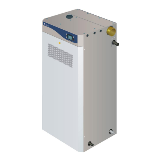
Gas Fired Humidifier
SKG3 Series
INSTALLATION INSTRUCTIONS
Read and save these instructions
WARNING: Risk of fire or explosion. May
cause property damage, personal injury or loss
of life. Please follow installation instructions
carefully.
FOR YOUR SAFETY: Do not store or use
gasoline or other flammable vapors and liquids
in the vicinity of this appliance.
WHAT TO DO IF YOU SMELL GAS:
Do not try to light any appliance.
Do not touch any electrical switch,
and do not use telephones in your
building.
Immediately call your gas supplier from
an off-site telephone.
Follow the gas supplier's instructions.
If you cannot reach your gas supplier,
call the fire department.
WARNING: Risk of injury or property damage.
Installation and service must be performed by a
qualified installer, service agency, or the gas
supplier.
SKG3-IOM – Rev.: 180313
4011008
Advertisement
Table of Contents

Related Manuals for Neptronic SKG3-110-1 N/P


Summary of Contents for Neptronic SKG3-110-1 N/P
-
Page 1: Installation Instructions
Gas Fired Humidifier SKG3 Series INSTALLATION INSTRUCTIONS WARNING: Risk of fire or explosion. May cause property damage, personal injury or loss of life. Please follow installation instructions carefully. FOR YOUR SAFETY: Do not store or use gasoline or other flammable vapors and liquids in the vicinity of this appliance. -
Page 2: Safety
Neptronic® systems are designed to be used with tap, reverse osmosis, demineralized or partially softened water. On no account attempt to introduce any other fluids or chemicals into the system without first consulting Neptronic or its authorized distributor. Water supply must not exceed the max pressure of 70 psig (480 kPa), or pressure limits laid out in the Installation Instructions and User Manual, and must comply with local regulations. -
Page 3: Foreword
Please observe the local regulations concerning the provision of electrical installations. Neptronic systems and its products are designed only for humidification use. Any Correct Use other application is not considered appropriate for the intended purpose. The manufacturer cannot be made liable for any damage resulting from incorrect use. -
Page 4: Table Of Contents
SKG3 Gas Fired Humidifier Installation Instructions and User Manual Table of Contents Safety ..............................1 Foreword ............................2 Table of Contents ..........................3 Technical Specifications ........................4 Dimensions & Weights ........................5 Installation Overview ........................10 Stage 1 – Unit Positioning and Mounting ..................11 Stage 2 –... -
Page 5: Technical Specifications
[315] [100] Notes: 1 - Maximum static duct pressure is 5” w.c. (1.25 kPa). For higher static duct pressures, consult Neptronic or its authorized distributor. 2 - Standard humidifier is designed for natural ventilation combustion air. “Ducted Combustion Air” option is available... -
Page 6: Dimensions & Weights
No of Steam Dimensions in inches [mm] Nb of Lb (Kg) Model Steam Outlet module Full of Outlets Diam. Empty water SKG3-110-1 N/P SKG3-155-1 N/P Ø3” SKG3-180-1 N/P [76] [1372] [610] [560] [230] [460] [145] [200] SKG3-210-1 N/P SKG3-265-2 N/P SKG3-310-2 N/P Ø3”... - Page 7 Nb of Drain Water Flue Model module Outlet Drain Inlet Inlet Outlet Diam. Diam. Diam. Diam. Diam. SKG3-110-1 N/P ؽ” Ø3/4’’ ؽ” Ø1” NPT Ø3” SKG3-155-1 N/P SKG3-180-1 N/P [20] [15] [25] [76] [15] SKG3-210-1 N/P SKG3-265-2 N/P ؽ” ؽ”...
- Page 8 Ducted combustion air dimensions - Fig. 4 (dimensions in bracket are in mm) Dimensions in inches [mm] No of No of Model modules inlet inlet Diam. SKG3-110-1 N/P Ø2’’ 17.6’’ 13.8’’ SKG3-155-1 N/P SKG3-180-1 N/P [51] [448] [352] SKG3-210-1 N/P SKG3-265-2 N/P Ø2’’...
- Page 9 (dimensions in bracket are in mm) (dimensions in bracket are in mm) Dimensions in inches [mm] Weight Lbs [Kg] No of Model Full of modules Empty water SKG3-110-1 N/P 24’’ 73-1/2’’ 25-1/2’’ 33-1/8’’ SKG3-155-1 N/P SKG3-180-1 N/P [1867] [647] [841]...
- Page 10 Caution must be exercised to ensure balanced load before lifting. Lifting of SKG3 Steam Humidifier MUST ALWAYS be done using the appropriate Neptronic Lifting Bracket (sold separately). Lifting sling angle must be greater than 30˚ to the horizontal. Optional weather proof enclosure is provided with four (4) lifting eyelets located at each corner on the top of the enclosure, see fig.
-
Page 11: Installation Overview
SKG3 Gas Fired Humidifier Installation Instructions and User Manual Installation Overview All installation work must comply with local regulations. All work related to the installation of the SKG3 Steam Humidifier MUST only be performed by skilled and qualified technical personnel (e.g. qualified gas installer, fitters, electricians, plumbers or technicians with appropriate training). -
Page 12: Stage 1 - Unit Positioning And Mounting
SKG3 Gas Fired Humidifier Installation Instructions and User Manual Stage 1 – Unit Positioning and Mounting Safety Any installation work MUST be carried out by suitably qualified personnel. Considerations The following considerations must be taken into account before deciding on the location of the SKG3 Steam Humidifier: ... - Page 13 SKG3 Gas Fired Humidifier Installation Instructions and User Manual Stage 1 – Unit Positioning and Mounting 20'’ (510) minimum 24'’ (600) minimum 24'’ (600) minimum 30'’ (800) minimum Standard enclosure clearance - Fig. 12 (dimensions in bracket are in mm) Weather proof enclosure clearance - Fig.
-
Page 14: Stage 2 - Steam Distribution Installation
4 ¼’’ (108mm) up to 528lb/h (240kg/h) 5 ¼’’ (133mm) up to 560lb/h (255kg/h) All humidifiers below 220lb/h (100kg/h) capacity must use standard Neptronic® S.A.M.E2 steam distribution pipes. Multi-Steam can be offered if shorter absorption distances are required. All humidifiers above 220lb/h (100kg/h) capacity must use the Multi-Steam. - Page 15 SKG3 Gas Fired Humidifier Installation Instructions and User Manual Stage 2 – Steam Distribution Installation Steam Outlet Configuration for Weather Proof Integrated steam manifold Enclosure Steam outlet Weather proof enclosure single steam outlet - Fig. 17 The SKG3 humidifier with weather proof enclosure is provided with an integrated steam manifold with an outlet located on either one of the sides of the humidifier.
- Page 16 SKG3 Gas Fired Humidifier Installation Instructions and User Manual Stage 2 – Steam Distribution Installation The minimum steam manifold length that can be used with the SKG3-110-1 to Selection of SKG3-210-1 is 35’’ (900mm). Any manifold below this dimension will have Steam insufficient outlet spigots to allow proper steam distribution.
- Page 17 SKG3 Gas Fired Humidifier Installation Instructions and User Manual Stage 2 – Steam Distribution Installation Steam Pipe Work to Duct Connections (SKG3-110 to 210) SKG3-110 Insulated pipe Min. 2/5 H Air Duct Min. 7° pipe slope Ø3'’ (76) Min. 4'’ (100) Static pressure + 2'’...
- Page 18 SKG3 Gas Fired Humidifier Installation Instructions and User Manual Stage 2 – Steam Distribution Installation Selection of For all Multi-Steam units, use the Neptronic® Humidisoft program to size the Multi-Steam unit. Where two Multi-Steam units are required with duties in excess of 528lb/h (240kg/h), make your selection using the following rules: ...
- Page 19 SKG3 Gas Fired Humidifier Installation Instructions and User Manual Stage 2 – Steam Distribution Installation Steam Pipe Work to Duct Connections (SKG3-110 to 810) SKG3-110 to 265 Air duct Insulated pipe Min. 7° pipe slop Ø3'’ (76) Multisteam Static pressure + 2'’...
- Page 20 SKG3 Gas Fired Humidifier Installation Instructions and User Manual Stage 2 – Steam Distribution Installation SKG3-505 to 610 Air Duct Min. 7° pipe slope Insulated pipe Ø5 ¼'’ (133) Ø3'’ (76) (x3) ؽ'’ (15) Static pressure + 2'’ (50) ؾ'’ (22) Steam pipe work 3 modules - Fig.
-
Page 21: Stage 3 - Gas Supply Connection
SKG3 Gas Fired Humidifier Installation Instructions and User Manual Stage 3 – Gas Supply Connection CAUTION: Gas piping installation MUST comply with all local codes and regulations, and current ANSI Z223.1, ‘’National Fuel Gas Code’’ or CAN/CSA-B149. Gas pressure to the humidifier MUST never exceed 26’’ w.c. (6kPa). A manual shut off valve (not supplied) MUST be installed on the gas supply line to the humidifier. -
Page 22: Stage 4 - Water Supply Installation
Water supply installation must conform to local codes and regulations. Any installation work must be carried out by suitably qualified personnel. Water Inlet The Neptronic® SKG3 Humidifier is designed to be used with tap, reverse Specifications osmosis, de-ionized and de-mineralized water. -
Page 23: Stage 5 - Water Drain Connection
SKG3 Gas Fired Humidifier Installation Instructions and User Manual Stage 5 – Water Drain Connection Water drain installation must conform to local codes and regulations. Any installation work must be carried out by suitably qualified personnel. Water Drain Water drain temperature: 140˚F (+60˚C) Specification Main Drain Outlet Pan Drain outlet... -
Page 24: Stage 6 - Combustion Air Installation
SKG3 Gas Fired Humidifier Installation Instructions and User Manual Stage 6 – Combustion Air Installation CAUTION: Combustion and room ventilation air must conform to local codes and regulations and to section 7.2, 7.3 or 7.4, Air for Combustion and Ventilation of the current ANSI Z223.1 ‘’National Fuel Gas Code’’... - Page 25 Installation (1) Number of Minimum Minimum Model Module Low level High level opening - opening - inlet outlet ) [cm ) [cm SKG3-110-1 N/P [240] [240] SKG3-155-1 N/P [360] [360] SKG3-180-1 N/P [420] [420] SKG3-210-1 N/P [480] [480] SKG3-265-2 N/P [600]...
- Page 26 SKG3 Gas Fired Humidifier Installation Instructions and User Manual Stage 6 – Combustion Air Installation Natural Ventilation Installation High level opening Outside Wall Low level opening Humidifier’s Air openings Natural ventilation configuration - Fig. 34 Ducted Combustion Air “Ducted Combustion Air” option, also called “Sealed Combustion”, is available upon request.
- Page 27 SKG3 Gas Fired Humidifier Installation Instructions and User Manual Stage 6 – Combustion Air Installation Ducted Combustion Air Single Humidifier Ø 2'’ (51) minimum SKG3-110 to 210 Humidifier inlet Ø 2'’ (51) Ducted combustion air 1 module - Fig. 35 (dimensions in bracket are in mm) 2 Modules Humidifier...
- Page 28 SKG3 Gas Fired Humidifier Installation Instructions and User Manual Stage 6 – Combustion Air Installation 3 Modules 1 to 3 outlets manifold Ø 6'’ (150) minimum Humidifier SKG3-505 to 610 Ø 2'’ (51) minimum Humidifier inlet Ø 2'’ (51) Ducted combustion air - Fig. 37 (dimensions in bracket are in mm) 4 Modules Humidifier...
-
Page 29: Stage 7 - Flue Gas Venting Connection
Minimum flue gas venting pipe upward gradient must be ¾’’ (20mm) in 40’’ (1m) horizontal run or as per flue gas venting manufacturer’s instructions. The Neptronic® SKG3 Steam Humidifier is a condensing appliance. As such, its high efficiency may cause condensation in the flue gas venting. - Page 30 SKG3 Gas Fired Humidifier Installation Instructions and User Manual Stage 7 – Flue Gas Venting Connection Minimum When flue gas terminal is located in outside air: Spacing Minimum spacing Building or other element (in) [mm] Below adjacent opening (window, air vent or any 12 [300] other ventilation opening) 3 [75]...
-
Page 31: Stage 8 - Electrical Supply And Installation
SKG3 Gas Fired Humidifier Installation Instructions and User Manual Stage 8 – Electrical Supply and Installation Electrical The SKG3 Steam Humidifier requires a 120, 208 or 240V single phase supply. Power Supply Weather proof Standard Model Voltage (V) enclosure Current (A) option (A) 120 –... -
Page 32: Stage 9 - Electrical Control Connections
Installation Instructions and User Manual Stage 9 – Electrical Control Connections Electrical Control The Neptronic® SKG3 Steam Humidifier has a modulating control system and Connections requires an analog control signal. All controls connections have been grouped on a specific Interface P.C.B. - Page 33 T B 2 H R O 2 0 Control signal from HRO20 humidity controller - Fig. 43 Humidifier The Neptronic® SKG3 Steam Humidifier can be installed in conjunction with the Control with Neptronic® SHR10 or SHC80 humidity sensors. Humidity Sensors...
- Page 34 The Neptronic® SKGE3 modulating Steam Humidifier can be installed in conjunction with a VAV system, in this case the Neptronic® SHC80 duct humidity sensor placed in the supply air will act as a high level duct humidity sensor. Humidity will be controlled by the Neptronic®...
-
Page 35: Stage 9 - Bacnet ® Interface Set-Up
SKG3 Gas Fired Humidifier Installation Instructions and User Manual Stage 9 – BACnet Interface Set-up ® Important Note ® This page describes the BACnet interface set-up. ® “BACnet interface’’ option is available only upon request. Dip Switch Pull Up enable Adjustment for RS-232 120 Ohm terminaison (last node) enable... -
Page 36: Initial Verification
SKG3 Gas Fired Humidifier Installation Instructions and User Manual Initial Verification Initial verification and start-up (commissioning) must be carried out by suitable qualified personnel. 1. Ensure that the humidifier cabinet is installed in a location where the Clearance humidifier can be serviced correctly. 2. - Page 37 SKG3 Gas Fired Humidifier Installation Instructions and User Manual Start-Up 1. Proceed to start-up the humidifier as follows: a) Open the front access door of the humidifier cabinet; ensure that the manual drain valve is closed. b) Start up the humidifier by pushing the (ON/OFF) button located on the humidifier control panel.
-
Page 38: Commissioning - Operation Description
Installation Instructions and User Manual Commissioning – Operation Description Control Panel The control panel of the Neptronic® SKG3 Steam humidifier is equipped with a user friendly LCD display and extensive access to status, alarms, and set-up menus. Description Blue Power ON LED... -
Page 39: Operation Display
SKG3 Gas Fired Humidifier Installation Instructions and User Manual Operation Display During normal operation, the following display indicates the main information about Operation Scrolling the system: Messages on Display DEMAND: 100% OUTPUT: 100% ROOM HUMIDITY 30%RH Scrolled Message Description ROOM SETPOINT Current room setpoint in % RH. -
Page 40: Status Menu
SKG3 Gas Fired Humidifier Installation Instructions and User Manual Status Menu Display Description STATUS Room Relative Humidity: Room Rel. Humidity 64%RH Displays the room relative humidity if a room humidistat is connected to the humidifier. STATUS System Demand: System Demand 64,3% Displays the humidity demand from the system. -
Page 41: Control Set-Up Menu
SKG3 Gas Fired Humidifier Installation Instructions and User Manual Control Set-up Menu Display Description Values Control Mode: External CONTROL SETUP Selection of control mode. Internal Control Mode If External is selected, the control demand will be received Com Port INTERNAL by the analog input. - Page 42 SKG3 Gas Fired Humidifier Installation Instructions and User Manual Control Set-up Menu Hi Limit SetPoint: CONTROL SETUP Voltage or Amp. Hi Limit SetPoint Selection of high Limit setpoint settings. From 0 to 10 V Volt/mA: Voltage or 2 to 10 V Vin Min.: 2.00V Allows you to select the voltage or current signal and the Vin Max.: 10.00V...
-
Page 43: System Set-Up Menu
SKG3 Gas Fired Humidifier Installation Instructions and User Manual System Set-up Menu Display Description Values SYSTEM SETUP Service Timer: From 400 to 3000 Hrs Service Timer Selection of delay between service alarms. Increment: 100 Hrs 1000 Hrs Value is indicated in Hours. Default:1000 Hrs Auto Drain Delay: SYSTEM SETUP... - Page 44 SKG3 Gas Fired Humidifier Installation Instructions and User Manual System Set-up Menu Display Description Values Chimney Temperature Offset: SYSTEM SETUP From -10 to 10˚C Selection of chimney temperature offset for each module, in Chimney Temp. Offset H1: 0°C order to adjust reading of the chimney temperature probe to Increment: 1˚C H2: 1°C proper temperature.
-
Page 45: Alarms Menu
SKG3 Gas Fired Humidifier Installation Instructions and User Manual Alarms Menu Display Description Operation Period: Displays the running hours countdown, it displays the reverse number of hours of Display # 107. ALARMS IMPORTANT: Operation Period This countdown must be reset after servicing in order to remove the alarm for call of H1: 1000Hr H2: 800Hr service. -
Page 46: List Of Alarms
SKG3 Gas Fired Humidifier Installation Instructions and User Manual List of Alarms No alarm must be reset prior to identifying and rectifying the cause of fault. Please refer to the troubleshooting guide for help on identifying and resolving potential problems. When an alarm is indicated by the LCD display, the red LED Alarm will flash. -
Page 47: Diagnostics Menu
SKG3 Gas Fired Humidifier Installation Instructions and User Manual Diagnostics Menu Display Description Input Voltage: Displays the analog inputs: DIAGNOSTICS Input Voltage Input #1: Control setpoint input voltage Input #1: 7.15V Input #2: Room humidity input voltage Input #2: 7.13V Input #3: Duct humidity input voltage Input #3: 7.14V Value indicated is in Volts. -
Page 48: Com Port Set-Up Menu
SKG3 Gas Fired Humidifier Installation Instructions and User Manual Com Port Set-up Menu Display Description Values Com Port Speed: COM PORT SET UP Com Port Speed N/A Baud Default: N/A N/A Baud Not Applicable, communication speed unit is not a variable. The communication speed is expressed in Baud. -
Page 49: Personal Notes
SKG3 Gas Fired Humidifier Installation Instructions and User Manual Personal Notes... -
Page 50: Exploded Views & Parts List
SKG3 Gas Fired Humidifier Installation Instructions and User Manual Exploded Views & Parts List General General exploded view - Fig. 50 Item Description Model Part number SKG Cabinet SW G1012 All models Evaporation chamber assembly See detail Front door assembly See detail Master (1 ) module... - Page 51 SKG3 Gas Fired Humidifier Installation Instructions and User Manual Exploded Views & Parts List Item 2 – Evaporation chamber assembly detail Evaporation chamber exploded view - Fig. 51 Item Description Model Part number Water tank All models SW G3208 Water tank gasket All models SW G2101 Band clamp...
- Page 52 SKG3 Gas Fired Humidifier Installation Instructions and User Manual Exploded Views & Parts List Item 3 - Door assembly detail Door assembly detail - Fig. 52 Item Description Model Part number Front door SP G1012-5 All models Air filter SP G4202 All models Air filter holder SP G1012-27...
- Page 53 SKG3 Gas Fired Humidifier Installation Instructions and User Manual Exploded Views & Parts List Item 11 – Igniter assembly Igniter assembly - Fig. 54 Item Description Model Part number Igniter holder assembly All models SW GIGNHOLD-ASSY 120V SW GIGNITER-120 Igniter 208 or 240V SW GIGNITER-230 Item 14 –...
- Page 54 SKG3 Gas Fired Humidifier Installation Instructions and User Manual Exploded Views & Parts List Water level sensor assembly Water level sensor assembly - Fig. 56 Item Description Model Part number Water level sensor assembly All models SW GWATLEV-ASSY Water level sensor All models SW GWATLEV-SUB...
-
Page 55: Multiple Modules Composition Table
Module description - Fig.57 Humidifier No of Module model number & quantity SKG100 SKG150 SKG180 SKG200 Model Modules SKG3-110-1 N/P SKG3-155-1 N/P SKG3-180-1 N/P SKG3-210-1 N/P SKG3-265-2 N/P SKG3-310-2 N/P SKG3-350-2 N/P SKG3-405-2 N/P SKG3-505-3 N/P SKG3-560-3 N/P SKG3-610-3 N/P... - Page 56 400 Lebeau blvd, Montreal, Qc, H4N 1R6, Canada www.neptronic.com Toll free in North America: 1-800-361-2308 Tel.: (514) 333-1433 Fax: (514) 333-3163 Customer service fax: (514) 333-1091 Monday to Friday: 8:00am to 5:00pm (Eastern time)
Need help?
Do you have a question about the SKG3-110-1 N/P and is the answer not in the manual?
Questions and answers