Table of Contents
Advertisement
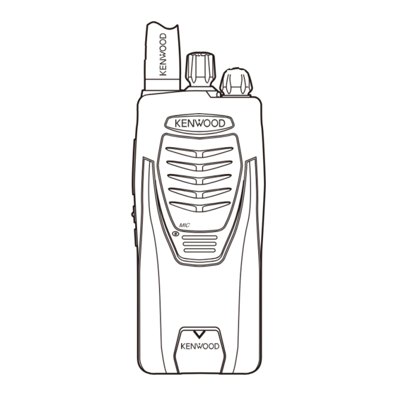
UHF FM TRANSCEIVER
TK-361SA
SERVICE MANUAL
Whip antenna
(T90-1039-25)
Badge
(B43-1190-04)
Button knob (PTT)
(K29-9308-23)
Button knob
(Lock/Scan)
(K29-9364-03)
Plastic cabinet assy
(A02-4043-03)
Knob (Channel)
(K29-9318-03)
Knob (Volume)
(K29-9309-03)
© 2008-2 PRINTED IN JA PAN
B51-8819-00 ( N ) PDF
CONTENTS
GENERAL .....................................................2
REALIGNMENT ...........................................3
DISASSEMBLY FOR REPAIR ......................5
CIRCUIT DESCRIPTION ..............................8
SEMICONDUCTOR DATA .........................11
COMPONENTS DESCRIPTION .................12
TERMINAL FUNCTION .............................12
PARTS LIST ...............................................13
EXPLODED VIEW ......................................19
PACKING ....................................................20
ADJUSTMENT ..........................................21
LEVEL DIAGRAM ......................................25
TX-RX UNIT (X57-6900-21) ...................26
SCHEMATIC DIAGRAM ............................30
BLOCK DIAGRAM .....................................34
KBH-10 (Belt Clip) ..................................36
KNB-30A (Ni-Cd Battery Pack) .............36
KSC-31 (Rapid Charger) ........................36
SPECIFICATIONS ......................................37
This product uses Lead Free solder.
Advertisement
Table of Contents

Related Manuals for Kenwood TK-361SA


Summary of Contents for Kenwood TK-361SA
-
Page 1: Table Of Contents
UHF FM TRANSCEIVER TK-361SA SERVICE MANUAL © 2008-2 PRINTED IN JA PAN B51-8819-00 ( N ) PDF CONTENTS GENERAL .............2 Knob (Channel) (K29-9318-03) REALIGNMENT ...........3 Knob (Volume) (K29-9309-03) DISASSEMBLY FOR REPAIR ......5 CIRCUIT DESCRIPTION ......8 Whip antenna (T90-1039-25) SEMICONDUCTOR DATA ......11 COMPONENTS DESCRIPTION ....12... -
Page 2: General
This applies to all parts : components, kits, or chassis. If the herein. Kenwood reserves the right to make changes to any part number is not known, include the chassis or kit number products herein at any time for improvement purposes. -
Page 3: Realignment
TK-361SA REALIGNMENT t Power switch/Volume control 1. Modes Turn clockwise to switch the power ON and counter- User mode clockwise to switch the power OFF. Rotate to adjust the volume. PC mode Data programming mode y LED indicator Indicates the transceiver status. Lights red while trans-... -
Page 4: Clone Mode
TK-361SA REALIGNMENT 4-5. Programming Software Description 5. Clone Mode The KPG-88D(M2) is the programming software for the 5-1. Outline transceiver supplied on a CD-ROM. The software on this “Clone Mode” copies the transceiver data to another disk allows a user to program the transceiver radios via Pro- transceiver. -
Page 5: Disassembly For Repair
TK-361SA REALIGNMENT • The source Unit and target Unit must be of the same Clone Frequency Table model type and destination in order for Clone to operate. Table number Frequency (MHz) • Clone mode cannot be accessed if “Super Lock” is acti- 463.9750... - Page 6 TK-361SA DISASSEMBLY FOR REPAIR ■ Removing the battery release lever from the ■ Assembling the battery release lever 1. Place the lever w onto the stopper q. case assembly 2. Place the thick spring e onto the lever. 1. Press the upper part of the lever toward the inside of the 3.
- Page 7 TK-361SA DISASSEMBLY FOR REPAIR 2. Mounting the chassis to the case assembly 4. The nuts of the volume knob and channel knob 1. Confirm that the waterproof packing attached to the Note that the shapes, colors and heights of nuts of the...
-
Page 8: Circuit Description
TK-361SA CIRCUIT DESCRIPTION The resulting signal passes through the XF201 MCF to 1. Frequency Confi guration cut the adjacent spurious and provide the opitimun charac- The receiver utilizes double conversion. The first IF is teristics, such as adjacent frequency selectivity. - Page 9 TK-361SA CIRCUIT DESCRIPTION ■ Receive Signaling ■ Unlock Detector • QT/DQT If a pulse signal appears at the LD pin of IC1, an unlock condition occurs, and the DC voltage obtained from C4, R5, The output signal from FM IC (IC201) enters the MCU and D1 causes the voltage applied to the MCU (IC405) to go (IC405) through IC301.
-
Page 10: Power Supply
TK-361SA CIRCUIT DESCRIPTION ■ Memory Circuit IC101 (2/2) compares the output voltage of IC101 (1/2) with the reference voltage from MCU (IC405). The output of Memory circuit consists of the MCU (IC405) and an EE- IC101 (2/2) controls the VG of the RF power amplifi er, Drive PROM (IC406). -
Page 11: Semiconductor Data
TK-361SA SEMICONDUCTOR DATA Micro Control Unit: 30622MAP490GU (TX-RX unit IC405) Pin No. Pin Name Function Pin No. Pin Name Function PCTV APC/BPF control data output BEEP BEEP Output Not used Channel selectable input EEPDAT I/O EEPROM data input/output Channel selectable input... -
Page 12: Components Description
TK-361SA COMPONENTS DESCRIPTION TX-RX Unit (X57-6900-21) Ref. No. Part Name Description Ref. No. Part Name Description Q305 Transistor DC switch/ SP Mute PLL system Q306 SP Mute switch IC101 Comparator (APC) Q316 SP Mute switch Q317,318 FET Audio switch IC201... -
Page 13: Parts List
Les articles non mentionnes dans le Parts No. ne sont pas fournis. Y : AAFES (Europe) X : Australia M : Oth er Areas Teile ohne Parts No. werden nicht geliefert. TK-361SA (Y50-5920-21) TX-RX UNIT (X57-6900-21) Desti- Desti- Ref. No. - Page 14 TK-361SA PARTS LIST TX-RX UNIT (X57-6900-21) Desti- Desti- Ref. No. Ad dress Parts No. Description Ref. No. Ad dress Parts No. Description parts nation parts nation CC73HCH1H101J CHIP C 100PF C159 CC73GCH1H020C CHIP C 2.0PF CC73HCH1H100C CHIP C 10PF C160...
- Page 15 TK-361SA PARTS LIST TX-RX UNIT (X57-6900-21) Desti- Desti- Ref. No. Ad dress Parts No. Description Ref. No. Ad dress Parts No. Description parts nation parts nation C268 CC73GCH1H220J CHIP C 22PF C411-413 CK73HB1H102K CHIP C 1000PF C269 CC73GCH1H020B CHIP C 2.0PF...
- Page 16 TK-361SA PARTS LIST TX-RX UNIT (X57-6900-21) Desti- Desti- Ref. No. Ad dress Parts No. Description Ref. No. Ad dress Parts No. Description parts nation parts nation L214 L41-8268-14 SMALL FIXED INDUCTOR (8.2NH) RK73HB1J331J CHIP R 1/16W L215 L41-2285-03 SMALL FIXED INDUCTOR (220NH)
- Page 17 TK-361SA PARTS LIST TX-RX UNIT (X57-6900-21) Desti- Desti- Ref. No. Ad dress Parts No. Description Ref. No. Ad dress Parts No. Description parts nation parts nation R256,257 RK73HB1J105J CHIP R 1.0M 1/16W R424,425 RK73HB1J473J CHIP R 1/16W R258 RK73FB2B000J CHIP R...
- Page 18 TK-361SA PARTS LIST TX-RX UNIT (X57-6900-21) Desti- Desti- Ref. No. Ad dress Parts No. Description Ref. No. Ad dress Parts No. Description parts nation parts nation Q203 KTC4080E-P TRANSISTOR Q204,205 3SK318 Q301 RT1P141U TRANSISTOR Q302 2SC4919 TRANSISTOR Q303 RT1N441U TRANSISTOR...
-
Page 19: Exploded View
TK-361SA EXPLODED VIEW MIC301 TX-RX unit CF201 : N14-0819-04 : N14-0832-04 M2.6 x 4 : N30-2604-48 D M2.6 x 6 : N30-2606-48 : N83-2005-48 Parts with the exploded numbers larger than 700 are not supplied. If a part reference number is listed in a box on the exploded view of the PCB, that part does not come with the PCB. -
Page 20: Packing
TK-361SA PACKING 9 Instruction manual (B62-2096-00) 67 AC adapter (W08-0971-35) 64 Whip antenna (T90-1039-25) Carton board Protection bag 57 Screw set (N99-2046-05) 45 Holder (SP/MIC) (J19-5472-03) 6 Cap (SP/MIC) (B09-0680-03) 68 Battery assy (W09-1001-15) 42 Packing fixture (H12-3179-05) 49 Belt hook... -
Page 21: Adjustment
TK-361SA ADJUSTMENT Test Equipment Required for Alignment Test Equipment Major Specifi cations Frequency Range 450 to 470MHz 1. Standard Signal Generator Modulation Frequency modulation and external modulation (SSG) Output –127dBm/0.1µV to greater than –47dBm/1mV Input Impedance 50Ω 2. Power Meter... - Page 22 TK-361SA ADJUSTMENT Controls Preparations for tuning the transceiver Before attempting to tune the transceiver, connect the Channel selector Antenna unit to a suitable power supply. Power switch/ Whenever the transmitter is tuned, the unit must be con- Volume control nected to a suitable dummy load (i.e. power meter).
- Page 23 TK-361SA ADJUSTMENT Common Section Measurement Adjustment Item Condition Specifi cations / Remarks Test- Unit Terminal Unit Parts Method equipment 1. Setting 1) BATT terminal voltage: 7.5V 2) SSG standard modulation MOD: 1kHz, DEV: 1.5kHz 2. VCO lock 1) CH: High...
- Page 24 TK-361SA ADJUSTMENT Measurement Adjustment Item Condition Specifi cations / Remarks Test- Unit Terminal Unit Parts Method equipment 9. DQT Fine 1) Test CH: Low, Center, High Power TX-RX Program- 0.40kHz ±40Hz Deviation (3 points) meter ming Deviation meter fi lter...
-
Page 25: Level Diagram
TK-361SA LEVEL DIAGRAM... -
Page 26: Pc Board
TK-361SA PC BOARD TX-RX UNIT (X57-6900-21) Component side view (J79-0165-09) F401 C405 D401 PCTV C401 C402 BATT+ C428 MIC301 L404 L402 – C430 CP404 R456 R338 R404 R406 C415 C217 IC405 C201 TH203 L403 IC403 C418 R424 R420 C410 R425... - Page 27 TK-361SA PC BOARD TX-RX UNIT (X57-6900-21) Component side view (J79-0165-09) R438 R134 R409 C412 R436 R410 R412 Q108 IC101 C413 L111 R403 CN13 R411 C403 R142 C414 R130 R139 C146 R140 D102 R141 R132 R127 R138 Q107 C140 R126 MIC301...
- Page 28 TK-361SA PC BOARD TX-RX UNIT (X57-6900-21) Foil side view (J79-0165-09) S402 S401 S403 C268 R256 D104 L228 R254 R253 C156 L223 C254 C168 C267 Q205 C251 D203 R241 C247 R145 C158 D204 C262 R249 D210 C265 L215 C258 C275 R258...
-
Page 29: Pc Board Tx-Rx Unit (X57-6900-21)
TK-361SA PC BOARD TX-RX UNIT (X57-6900-21) Foil side view (J79-0165-09) S402 CN201 C421 C427 XF201 R226 C225 D402 R215 R227 C219 C443 C241 C228 C426 R233 CD201 R236 C207 R209 L290 C348 C208 R206 CF201 R213 C233 C210 C215 Q301... -
Page 30: Schematic Diagram
TK-361SA SCHEMATIC DI A GRAM TX-RX UNIT (X57-6900-21) PLL_CLK PLL_DAT PLL_STB 2.74V 100k PLL SYSTEM MB15A02PFV2E1 4.82V 470p 2SC5108(Y)F RECTIFICATION PLL IC F_IN AMP 470p 4.76V MA2S111-F 0.01u R32-0736-05 4.9V L77-1931-05 F401 2.5A L401 4.7V BATT 100k 0.71V 12.8MHz BATT oUTPUT 4.7u... - Page 31 TK-361SA SCHEMATIC DIAGRAM TX-RX UNIT (X57-6900-21) TX/RX T:3.37V T:2.85V RF SW D2,4,6,7 D101 VCO OSCILLATION (TX) C101 C102 4.73V 220n FREQUENCY RF BUFFER AMP HSC277 470p CONTROL 3.4V /TX VCO HVC376B 0.72V 2SC5108(Y)F RF AMP 2SC4619(P,Q) 100n 0.5p R:2.9V HVC376B VCO/TX T:3.0V...
- Page 32 TK-361SA SCHEMATIC DI A GRAM TX-RX UNIT (X57-6900-21) PRE-DRIVE AMP Q101 TX DRIVE AMP TX FINAL AMP R:7.63V T:3.44V T:4.89V 2SK3077F T:7.45V Q102 Q103 L412 L103 L107 C107 C112 C123 R103 R112 R150 2SK2596-E R903 R151 R152 2SK3476-F 8.2n 8.2n 1.2n...
- Page 33 TK-361SA SCHEMATIC DIAGRAM TX-RX UNIT (X57-6900-21) ANT SW D122 C160 C163 C166 0.75p HVC131 STRIP LINE D103 R137 C152 C158 L225 L226 L224 CN13 100p HVC131 ANT SW L223 R145 R147 ANT SW ANT SW RX LO1 R:5V L410 R:5V...
-
Page 34: Block Diagram
TK-361SA BLOCK DIAGRAM X57-6900-21 MB15A02PFV2E1 IC404 IC403 BD4840FVE BD4845FVE PLL_DAT PLL_CLK PLL_STB RESET RESET Q4 2SK508NV(K52) D401 RB521S-30 D2,D4,D6,D7 HVC376B D10 1SV278F PROTECT Loop Q405 Filter RT1P237U-T111 IC401 XC6204B502MR RT1P430U 12.8MHz L77-1931-05 5C_C QTTCXO Q3 2SK508NV(K52) Q403 CPH3317 D3,D5,D8,D9 HVC376B... - Page 35 TK-361SA BLOCK DIAGRAM Q2 2SC5108(Y)F TX/RX: 463.975 ~464.375MHz V(K52) Q101 Q102 Q103 D101,D202 Q100 D122,D103,D104,D106 HVC376B 2SK3077F HSC277 2SC4619(P,Q) 2SK2596-E 2SK3476-E 2SC4619(P,Q) HVC131 Q6 2SC5108(Y)F BUFF P430U Q104 RT1N141U Q109 IC101 Q105 2SK879(Y)F RT1P441U TA75W01FUF CURRENT Q108 2SK1824-A DCSW Q8 2SC5383-T111...
-
Page 36: Optional Accessories
TK-361SA OPTIONAL ACCESSORIES KBH-10 (Belt Clip) KSC-31 (Rapid Charger) ■ External View ■ External View ■ Specifi cations Charging current ..........850mA ±5% Charging time .......KNB-30A : Approx.120 minutes Dimensions (Charger only) ..86.3W x 46.2H x 100.0D (mm) KNB-30A (Ni-Cd Battery Pack) 3-3/8W x 1-7/8H x 4D (inches) Weight (Charger only) ......Approx.100g / 0.22 lbs... -
Page 37: Specifications
TK-361SA SPECIFICATIONS General Frequency Range ................463.975~464.375MHz Number of Channels ................8 Channel Spacing ................12.5kHz PLL Channel Stepping ............... 5kHz, 6.25kHz Operating Voltage ................7.5 V DC ±20% Battery Life (5-5-90 duty cycle with KNB-30A battery) ...... Battery Saver off : Approx. 10 hours Battery Saver on and QT on : Approx. - Page 38 Unit 3712-3724, Level 37, Tower one Metroplaza, 223 Hing Fong Road, Bp 58416 Villepinte, 95944 Roissy Ch De Gaulle Cedex Kwai Fong, N.T., Hong Kong KENWOOD House, Dwight Road, Watford, Herts., 1 Ang Mo Kio Street 63, Singapore 569110 WD18 9EB United Kingdom...
- Page 39 TK-361SA TK-361SA PC BOARD PC BOARD TX-RX UNIT (X57-6900-21) Component side view (J79-0165-09) TX-RX UNIT (X57-6900-21) Component side view (J79-0165-09) R438 R134 R409 C412 F401 R436 R410 R412 Q108 C405 IC101 C413 L111 R403 D401 CN13 PCTV R411 C401 C403...
- Page 40 TK-361SA TK-361SA PC BOARD PC BOARD TX-RX UNIT (X57-6900-21) Foil side view (J79-0165-09) TX-RX UNIT (X57-6900-21) Foil side view (J79-0165-09) S402 S401 S403 C268 R256 CN201 D104 C427 C421 L228 R254 R253 C156 L223 XF201 C254 R226 C225 C168 C267...
- Page 41 TX-RX UNIT (X57-6900-21) PRE-DRIVE AMP ANT SW D122 C160 C163 C166 TX FINAL AMP T:3.44V Q101 T:4.89V TX DRIVE AMP R:7.63V 2SK3077F 0.75p Q102 T:7.45V Q103 STRIP LINE HVC131 C107 C112 L103 L412 C123 L107 C152 D103 L225 L226 PLL_CLK TX/RX R103 R112...
- Page 42 X57-6900-21 IC403 MB15A02PFV2E1 Q2 2SC5108(Y)F IC404 BD4840FVE BD4845FVE TX/RX: 463.975 PLL_DAT ~464.375MHz PLL_CLK PLL_STB RESET RESET D401 Q4 2SK508NV(K52) D101,D202 Q100 Q101 Q102 Q103 D122,D103,D104,D106 RB521S-30 D2,D4,D6,D7 HVC376B HSC277 2SC4619(P,Q) 2SK3077F 2SK2596-E 2SK3476-E 2SC4619(P,Q) HVC131 D10 1SV278F Q6 2SC5108(Y)F PROTECT Loop BUFF Q405...
Need help?
Do you have a question about the TK-361SA and is the answer not in the manual?
Questions and answers