Kenwood TK-260G Instruction Manual
Vhf fm transceiver/ uhf fm transceiver
Hide thumbs
Also See for TK-260G:
- Service manual (50 pages) ,
- Instruction manual (22 pages) ,
- Service manual (4 pages)

Related Manuals for Kenwood TK-260G


Summary of Contents for Kenwood TK-260G
-
Page 1: Instruction Manual
TK-260G/TK-360G VHF FM TRANSCEIVER/ UHF FM TRANSCEIVER INSTRUCTION MANUAL TRANSCEPTOR DE FM VHF/ TRANSCEPTOR DE FM UHF MANUAL DE INSTRUCCIONES KENWOOD CORPORATION ©B62-1129-10(K)(MC) 09 08 07 06 05 04 03 02 01 00... - Page 2 TK-260G/TK-360G VHF FM TRANSCEIVER/ UHF FM TRANSCEIVER INSTRUCTION MANUAL...
- Page 3 For information on Ni-Cd battery recycling in your area, call (toll free) 1-800-8-BATTERY (1-800-822-8837). KENWOOD’s involvement in this program is part of our commitment to preserve our environment and conserve our natural resources.
-
Page 4: Models Covered By This Manual
MODELS COVERED BY THIS MANUAL • TK-260G: VHF FM Transceiver • TK-360G: UHF FM Transceiver NOTICES TO THE USER WARNING: GOVERNMENT LAW PROHIBITS THE OPERATION OF UNLICENSED RADIO TRANSMITTERS WITHIN THE TERRITORIES UNDER GOVERNMENT CONTROL. ILLEGAL OPERATION IS PUNISHABLE BY FINE OR IMPRISONMENT OR BOTH. -
Page 5: Precautions
Do not place the transceiver in excessively dusty areas, humid areas, nor on unstable surfaces. • If an abnormal odor or smoke is detected coming from the transceiver, switch OFF the power immediately and remove the optional battery pack from the transceiver. Contact your KENWOOD dealer. -
Page 6: Table Of Contents
CONTENTS FCC WARNINGS/ BATTERY ADVISORY ...... Inside Front Cover MODELS COVERED BY THIS MANUAL ...... i NOTICES TO THE USER ..........i PRECAUTIONS ............ii THANK YOU! .............. 1 UNPACKING AND CHECKING EQUIPMENT ..... 1 Supplied Accessories ........2 PREPARATION ............3 Installing/Removing the Optional Battery Pack .. -
Page 7: Thank You
UNPACKING AND CHECKING EQUIPMENT Note: The following instructions are for use by your KENWOOD dealer, an authorized KENWOOD service facility, or the factory. Carefully unpack the transceiver. We recommend that you identify the items listed on the following page before discarding the packing material. -
Page 8: Supplied Accessories
Supplied Accessories I t e m Part Number Q t y . Belt hook J29-0624-XX Screw set N99-2012 -XX Speaker-mic jacks cap B09-0351-XX Locking bracket J21-4493-XX (for speaker-mic) Warranty card — Instruction manual B62-1129-XX Speaker-mic jacks cap Belt hook Screw set Locking bracket... -
Page 9: Preparation
PREPARATION Installing/Removing the Optional Battery Pack The optional KNB-14 or KNB-15A battery pack is not charged at the factory. Charge the pack before use. If after purchase or extended storage (greater than 2 months), battery capacity is found to be low, the battery pack needs recharging. - Page 10 2 Slide the battery pack along the back of the transceiver until the release catch on the base of the transceiver locks the battery pack in place. 3 To remove the battery pack, grasp the pack near its tabs, pull back on the release catch, then slide the pack away from the transceiver.
-
Page 11: Installing The Antenna
CAUTION: Do not recharge the battery pack if it is already fully charged. If you do this, you will overcharge the battery pack which may shorten its life or damage it. After recharging the battery pack, disconnect it from the charger. If, having recharged the battery pack, the power to the charger is turned off and then back on while the pack is still connected, recharging will start again and the battery pack will become... -
Page 12: Installing The Cap Over The Speaker-Mic Jacks
Installing the Cap Over the Speaker-Mic Jacks Use the supplied screw (3 mm x 6 mm) to install the cap over the speaker-mic jacks if a speaker- microphone is not used. Installing the Speaker-Microphone Insert the speaker-microphone plugs into the SP/MIC jacks. -
Page 13: Installing The Belt Hook
Installing the Belt Hook If necessary, attach the belt hook using the two 3 mm x 8 mm screws from the supplied screw set. -
Page 14: Getting Acquainted
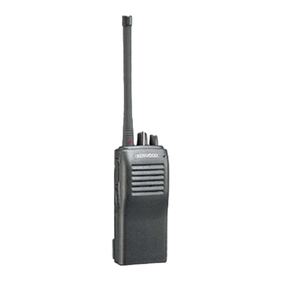
GETTING ACQUAINTED Antenna Speaker Microphone used The transceiver is shown with the optional KNB-14 battery pack installed. - Page 15 1 ANTENNA connector Connect the supplied antenna to this connector. 2 LED indicator Lights red while transmitting. Flashes red while transmitting if the battery pack voltage is low. Recharge or replace the battery pack at this time. The LED lights green while receiving a station. The LED flashes orange if, while a channel programmed with 2-Tone signaling is selected, the same 2-Tone signaling is received as is programmed or you press...
- Page 16 6 MONI button Press to monitor activity on your selected channel. Also used with 2-Tone Signaling to mute the speaker after this function has opened squelch. 7 Speaker-microphone jacks If desired, connect a speaker-microphone here.
-
Page 17: Receiving
RECEIVING Your dealer may have programmed QT, DQT, or 2-Tone signaling for the channel that you select. If so programmed, you will hear transmissions from other transceivers IN YOUR SYSTEM ONLY! Otherwise, you will hear ALL TRANSMISSIONS made by ANY stations using the same channel. -
Page 18: Calling
Note: Your dealer selects one of four methods of operation for [MONI]: Hold down the button to open the squelch; release the button to • close the squelch, or • Hold down the button to deactivate QT, DQT, or 2-Tone decoding;... -
Page 19: Time-Out Timer (Tot)
Time-Out Timer (TOT) The purpose of the time-out timer is to automatically interrupt continuous transmissions after a specified time elapses. Holding down [PTT] for longer than the programmed time causes the transceiver to stop transmitting and generate a warning tone. Releasing [PTT] cancels the warning tone. -
Page 20: Battery Voltage Level
Battery Voltage Level While holding down [PTT], the battery voltage level is checked. When the voltage level drops to the predetermined value, the LED flashes red. When the voltage level drops further, the transceiver stops transmitting and generates an alarm. If this occurs, recharge the battery pack. -
Page 21: Channel Chart
CHANNEL CHART Model TK- Serial No.: Encode Decode Channel RX Freq. TX Freq. Signaling Signaling Dealer Name & Address: Dealer Telephone No.: Date Purchased:...
Need help?
Do you have a question about the TK-260G and is the answer not in the manual?
Questions and answers