
Related Manuals for MSI 651M


Summary of Contents for MSI 651M
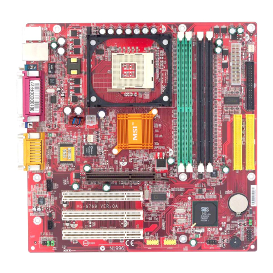
- Page 1 651M/650GXM Combo Series MS-6769 (v1.X) Micro ATX Mainboard Version 1.0 G52-M6769X1-K01...
-
Page 2: Fcc-B Radio Frequency Interference Statement
Manual Rev: 1.0 Release Date: March 2003 FCC-B Radio Frequency Interference Statement This equipment has been tested and found to comply with the limits for a class B digital device, pursuant to part 15 of the FCC rules. These limits are designed to provide reasonable protection against harmful interference when the equip- ment is operated in a commercial environment. -
Page 3: Copyright Notice
Copyright Notice The material in this document is the intellectual property of MICRO-STAR INTERNATIONAL. We take every care in the preparation of this document, but no guarantee is given as to the correctness of its contents. Our products are under continual improvement and we reserve the right to make changes without notice. -
Page 4: Safety Instructions
Safety Instructions Always read the safety instructions carefully. Keep this User’s Manual for future reference. Keep this equipment away from humidity. Lay this equipment on a reliable flat surface before setting it up. The openings on the enclosure are for air convection hence protects the equipment from overheating. -
Page 5: Table Of Contents
Safety Instructions ..................v Chapter 1. Getting Started ................ 1-1 Mainboard Specifications ..............1-2 Mainboard Layout ................1-5 MSI Special Features ................1-6 PC Alert™ 4 ................... 1-6 Live BIOS™/Live Driver™ ............1-8 Live Monitor™ ................1-9 Chapter 2. Hardware Setup ............... 2-1 Quick Components Guide .............. - Page 6 USB Connector ................2-12 Serial Port Connectors: COMA ........... 2-13 VGA Connector (Optional) ............2-13 RJ-45 LAN Jack (Optional) ............2-14 Audio Port Connectors ............... 2-14 Midi/Joystick Connector ............. 2-15 Parallel Port Connectors: LPT1 ............ 2-15 Connectors ..................2-16 Front Disk Drive Connector: FDD1 ..........2-16 CD-In Connector: JCD1 ...............
- Page 7 Advanced Chipset Features ............... 3-12 Integrated Peripherals ................ 3-14 Power Management Setup ..............3-18 PNP/PCI Configurations ..............3-22 PC Health Status ................3-24 Frequency/Voltage Control ..............3-25 Load Fail-Safe/Optimized Defaults ............. 3-27 Set Supervisor/User Password ............3-28 Appendix: Using 4- or 6-Channel Audio Function ........A-1 Installing the Audio Driver ..............
-
Page 8: Chapter 1. Getting Started
651/650GX (702 pin BGA) ® & SiS 962L MuTIOL Media I/O (371 BGA) chipsets and provides 6 USB 2.0 ports for high-speed data transmission. With all these special designs, the 651M/650GXM Combo delivers a high performance and professional desktop platform solution. -
Page 9: Mainboard Specifications
MS-6769 Micro ATX Mainboard Mainboard Specifications Core frequency from 1.7GHz to 2.8 GHz Socket 478 for P4 processors (Williamette 478 / Northwood 478 / Celeron 478) at 400 MHz (SiS 650GX) / 533 MHz (SiS 651) Chipset SiS 651/650GX (702 pin BGA) - High performance host interface 533 MHz (SiS 651) - High performance host interface 400 MHz (SiS 650GX) - 64 Bit high performance PC133/266 memory controller... - Page 10 Hardware Setup On-Board IDE Dual IDE controllers integrated in SiS 962L. Support Bus Master, Ultra DMA 66/100/133 operation modes. Can connect up to four IDE devices. On-Board Peripherals On-Board Peripherals include: - 1 floppy port supports 2 FDDs with 360K, 720K, 1.2M, 1.44M and 2. 88 Mbytes.
- Page 11 MS-6769 Micro ATX Mainboard Mounting 6 mounting holes. Others ® Support Intel Pentium4 /Celeron Socket 478 processor at 400/533 MHz System Bus frequencies Live BIOS/Live Driver Update PC2001 Compliant Suspends to RAM/Disk...
-
Page 12: Mainboard Layout
Top : Game port BIOS Bottom: Winbond Line-Out W83697HF Line-In AG P Slot JCD1 PCI Slot 1 BATT Codec PCI Slot 2 962L JSP1 JBAT1 PCI Slot 3 JFP1 JAUD1 JFP2 JUSB2 JUSB1 651M/650GXM Combo Series (MS-6769) v1.X Micro ATX Mainboard... -
Page 13: Msi Special Features
MS-6769 Micro ATX Mainboard MSI Special Features PC Alert™ 4 The PC Alert 4 is a utility you can find in the CD-ROM disk. The utility is just like your PC doctor that can detect the following PC hardware status during real time operation: monitor CPU &... - Page 14 (as shown below) with information about the CPU and chipset. Right-click the mouse to select the skin you want to switch to. Cute MSI Reminds You... The new feature COOLER XP will work only if your mainboard supports AMD Athlon XP CPU.
-
Page 15: Live Bios™/Live Driver
BIOS/drivers online so that you don’t need to search for the correct BIOS/driver version throughout the Web site. To use the function, you need to install the “MSI Live Update 2” application. After the installation, the “MSI Live Update 2”... -
Page 16: Live Monitor
Live Monitor™ The Live Monitor™ is a tool used to schedule the search for the latest BIOS/drivers version on the MSI Web site. To use the function, you need to install the “MSI Live Update 2” application. After the installation, the “MSI Live Monitor” icon (as shown on the right) will appear on the screen. -
Page 17: Chapter 2. Hardware Setup
Hardware Setup Chapter 2. Hardware Setup Hardware Setup This chapter tells you how to install the CPU, memory modules, and expansion cards, as well as how to setup the jump- ers on the mainboard. It also provides the instructions on con- necting the peripheral devices, such as the mouse, keyboard, etc. -
Page 18: Quick Components Guide
MS-6769 Micro ATX Mainboard Quick Components Guide DDR DIMMs, p.2-7 ATX1, p.2-9 SDR DIMMs, p.2-7 CPU, p.2-3 SYSFAN1, p.2-18 CONN1, p.2-10 Back Panel I/O, p.2-11 FDD1, p.2-16 CPUFAN1, p.2-18 IDE1, IDE2, JCD1, p.2-23 p.2-17 PCI Slots, p.2-25 JBAT1, p.2-24 JSP1, p.2-22 JFP1, p.2-19 JFP2, p.2-23 JAUD1, p.2-20... -
Page 19: Central Processing Unit: Cpu
CPU core speed Host Clock x Core/Bus ratio 100MHz x 17 1.7 GHz MSI Reminds You... Overheating Overheating will seriously damage the CPU and system, al- ways make sure the cooling fan can work properly to protect the CPU from overheating. -
Page 20: Cpu Installation Procedures For Socket 478
MS-6769 Micro ATX Mainboard CPU Installation Procedures for Socket 478 1. Please turn off the power and unplug the power cord before Open Lever installing the CPU. 2. Pull the lever sideways away Sliding 90 degree Plate from the socket. Make sure to raise the lever up to a 90- degree angle. -
Page 21: Installing The Cpu Fan
Hardware Setup Installing the CPU Fan As processor technology pushes to faster speeds and higher performance, thermal management becomes increasingly important. To dissipate heat, you need to attach the CPU cooling fan and heatsink on top of the CPU. Follow the instructions below to install the Heatsink/Fan: 1. - Page 22 MS-6769 Micro ATX Mainboard 5. Connect the fan power cable from the mounted fan to the 3-pin fan power connector on the board. fan power cable NOTES...
-
Page 23: Memory
(DIMM 1~2) DDR DIMM Slots (DDR 1~2) MSI Reminds You... Make sure that you install only one type of memory modules (either SDR or DDR) at one time. DO NOT install both types at the same time. For security reason, the system will automati- cally power off if you simultaneously install SDR &... -
Page 24: Ddr Module Combination
3. The plastic clip at each side of the DIMM slot will automatically close. Volt Notch MSI Reminds You... You can barely see the golden finger if the module is properly inserted in the socket. -
Page 25: Sdr Module Combination
2. Insert the DIMM memory module vertically into the DIMM slot. Then push it in. 3. The plastic clip at each side of the DIMM slot will automatically close. Volt Notch MSI Reminds You... You can barely see the golden finger if the module is properly inserted in the socket. -
Page 26: Power Supply
MS-6769 Micro ATX Mainboard Power Supply The mainboard supports ATX power supply for the power system. Be- fore inserting the power supply connector, always make sure that all compo- nents are installed properly to ensure that no damage will be caused. ATX 20-Pin Power Connector: CONN1 This connector allows you to connect to an ATX power supply. -
Page 27: Back Panel
Hardware Setup Back Panel The back panel provides the following connectors: Parallel Midi/Joystick Mouse (Optional) Keyboard USB Ports COMA VGA Port L-out L-in MIC Mouse Connector The mainboard provides a standard PS/2 ® mouse mini DIN connector ® ® for attaching a PS/2 mouse. -
Page 28: Keyboard Connector
MS-6769 Micro ATX Mainboard Keyboard Connector ® The mainboard provides a standard PS/2 keyboard mini DIN connec- ® ® tor for attaching a PS/2 keyboard. You can plug a PS/2 keyboard directly into this connector. Pin Definition SIGNAL DESCRIPTION Keyboard DATA Keyboard DATA No connection Ground... -
Page 29: Vga Monitor
Hardware Setup Serial Port Connectors: COMA The mainboard offers one 9-pin male DIN connector as serial port COM A. This port is 16550A high speed communication ports that send/receive 16 bytes FIFOs. You can attach a serial mouse or other serial device directly to it. Pin Definition SIGNAL DESCRIPTION... -
Page 30: Lan Jack (Optional)
1/8” Stereo Audio Connectors Line Out Line In MSI Reminds You... For advanced audio application, Realtek ALC 650 is provided to offer support for 6-channel audio operation and can turn rear audio connectors from 2-channel to 4-/6-channel audio. -
Page 31: Midi/Joystick Connector
Hardware Setup Midi/Joystick Connector You can connect a joystick or game pad to this connector. Parallel Port Connector: LPT1 The mainboard provides a 25-pin female centronic connector as LPT. A parallel port is a standard printer port that supports Enhanced Parallel Port (EPP) and Extended Capabilities Parallel Port (ECP) mode. -
Page 32: Connectors
MS-6769 Micro ATX Mainboard Connectors The mainboard provides connectors to connect to FDD, IDE HDD, case, modem, LAN, USB Ports, IR module and CPU/System/Power Supply FAN. Floppy Disk Drive Connector: FDD1 The mainboard provides a standard floppy disk drive connector that supports 360K, 720K, 1.2M, 1.44M and 2.88M floppy disk types. -
Page 33: Hard Disk Connectors: Ide1 & Ide2
IDE2 (Secondary IDE Connector) IDE2 can also connect a Master and a Slave drive. MSI Reminds You... If you install two hard disks on cable, you must configure the second drive to Slave mode by setting its jumper. Refer to the hard disk documentation supplied by hard disk vendors for jumper setting instructions. -
Page 34: Fan Power Connectors: Cpufan1/Sysfan1
SYSFAN1 +12V SENSOR CPUFAN1 MSI Reminds You... 1. Always consult the vendors for proper CPU cooling fan. 2. CPUFAN1 supports the fan control. You can install the PC Alert utility that will automatically control the CPU fan speed according to the actual CPU temperature. -
Page 35: Front Panel Connectors: Jfp1 & Jfp2
Hardware Setup Front Panel Connectors: JFP1 & JFP2 The mainboard provides two front panel connectors for electrical ® connection to the front panel switches and LEDs. JFP1 is compliant with Intel Front Panel I/O Connectivity Design Guide. JFP1 – Power Reset Power Switch... -
Page 36: Front Panel Audio Connector: Jaud1
Left channel audio signal to front panel AUD_RET_L Left channel audio signal return from front panel MSI Reminds You... If you don’t want to connect to the front audio header, pins 5 & 6, 9 & 10 have to be jumpered in order to have signal output directed to the rear audio ports. -
Page 37: Front Usb Connectors: Jusb1/Jusb2
Hardware Setup Front USB Connectors: JUSB1/JUSB2 The mainboard provides one USB 2.0 pin header JUSB1 that is compliant ® with Intel I/O Connectivity Design Guide. USB 2.0 technology increases data transfer rate up to a maximum throughput of 480Mbps, which is 40 times faster than USB 1.1, and is ideal for connecting high-speed USB inter- face peripherals such as USB HDD, digital cameras, MP3 players, printers, modems and the like. -
Page 38: Spdif Connector: Jsp1(Optional)
MS-6769 Micro ATX Mainboard SPDIF Connector: JSP1 (Optional) The connector is used to connect SPDIF (Sony & Philips Digital Inter- connect Format) interface for digital audio transmission. JSP1 Pin Definition SIGNAL SPDIF JSP1 The JSP1 supports SPDIF output only and can be connected to an external SPDIF Bracket for digital audio transmission. -
Page 39: Jumpers
JBAT1 Keep Data Clear Data MSI Reminds You... You can clear CMOS by shorting 2-3 pin while the system is off. Then return to 1-2 pin position. Avoid clearing the CMOS while the system is on; it will damage the mainboard. -
Page 40: Slots
MS-6769 Micro ATX Mainboard Slots The motherboard provides three 32-bit PCI bus slots. AGP Slots PCI Slots AGP (Accelerated Graphics Port) Slot The AGP slot allows you to insert the AGP graphics card. AGP is an interface specification designed for the throughput demands of 3D graphics. It introduces a 66MHz, 32-bit channel for the graphics controller to directly access main memory. -
Page 41: Pci Interrupt Request Routing
Hardware Setup PCI Interrupt Request Routing The IRQ, abbreviation of interrupt request line and pronounced I-R-Q, are hardware lines over which devices can send interrupt signals to the microprocessor. The PCI IRQ pins are typically connected to the PCI bus INT A# ~ INT D# pins as follows: Order 1 Order 2... -
Page 42: Chapter 3. Bios Setup
BIOS Setup Chapter 3. BIOS Setup BIOS Setup This chapter provides information on the BIOS Setup program and allows you to configure the system for optimum use. You may need to run the Setup program when: An error message appears on the screen during the system booting up, and requests you to run SETUP. -
Page 43: Entering Setup
MS-6769 Micro ATX Mainboard Entering Setup Power on the computer and the system will start POST (Power On Self Test) process. When the message below appears on the screen, press <DEL> key to enter Setup. Press DEL to enter SETUP If the message disappears before you respond and you still wish to enter Setup, restart the system by turning it OFF and On or pressing the RESET button. -
Page 44: Getting Help
Press <Esc> to exit the Help screen. MSI Reminds You... The items under each BIOS category described in this chapter are under continuous update for better system performance. -
Page 45: The Main Menu
MS-6769 Micro ATX Mainboard The Main Menu ® Once you enter Award BIOS CMOS Setup Utility, the Main Menu (Figure 1) will appear on the screen. The Main Menu allows you to select from twelve setup functions and two exit choices. Use arrow keys to select among the items and press <Enter>... - Page 46 BIOS Setup Frequency/Voltage Control Use this menu to specify your settings for frequency/voltage control. Load Fail-Safe Defaults Use this menu to load the BIOS values for the best system performance, but the system stability may be affected. Load Optimized Defaults Use this menu to load factory default settings into the BIOS for stable system performance operations.
-
Page 47: Standard Cmos Features
MS-6769 Micro ATX Mainboard Standard CMOS Features The items in Standard CMOS Features Menu are divided into 11 categories. Each category includes no, one or more than one setup items. Use the arrow keys to highlight the item and then use the <PgUp> or <PgDn> keys to select the value you want in each item. - Page 48 BIOS Setup ing items. Enter the information directly from the keyboard. This information should be provided in the documentation from your hard disk vendor or the system manufacturer. Access Mode The settings are CHS, LBA, Large, Auto. Capacity The formatted size of the storage device. Cylinder Number of cylinders.
-
Page 49: Advanced Bios Features
MS-6769 Micro ATX Mainboard Advanced BIOS Features Quick Boot Setting the item to Enabled allows the system to boot within 5 seconds since it will skip some check items Settings: Disabled, Enabled. Anti-Virus Protection The item is to set the Virus Warning feature for IDE Hard Disk boot sector protection. - Page 50 The system will boot from the Network drive. Disabled Disable this sequence. MSI Reminds You... Available settings for “1st/2nd/3rd Boot Device” vary depend- ing on the bootable devices you have installed. For example, if you did not install a floppy drive, the setting “Floppy” does not show up.
- Page 51 MS-6769 Micro ATX Mainboard Boot Up NumLock Status This setting is to set the Num Lock status when the system is powered on. Setting to On will turn on the Num Lock key when the system is powered on. Setting to Off will allow users to use the arrow keys on the numeric keypad. Setting options: On, Off.
- Page 52 BIOS Setup version supported by your operating system. To find out which version to use, consult the vendor of your operating system. Settings: 1.4, 1.1. HDD S.M.A.R.T. Capability This allows you to activate the S.M.A.R.T. (Self-Monitoring Analysis & Reporting Technology) capability for the hard disks. S.M.A.R.T is a utility that monitors your disk status to predict hard disk failure.
-
Page 53: Advanced Chipset Features
MS-6769 Micro ATX Mainboard Advanced Chipset Features MSI Reminds You... Change these settings only if you are familiar with the chipset. Advanced DRAM Control 1 Press <Enter> and the following sub-menu appears: DRAM Timing Control Selects whether DRAM timing is controlled by the SPD (Serial Presence Detect) EEPROM on the DRAM module. - Page 54 BIOS Setup RAS Active Time (Tras) This item allows you to control the number of DRAM clocks used for DRAM parameters Tras. Tras specifies the minimum clock cycles required for the active command to be transferred to the precharge command. Setting options: 4T, 5T, 6T, 7T. RAS to CAS Delay (Trcd) This field allows you to set the number of cycles for a timing delay between the CAS and RAS strobe signals, used when DRAM is written...
-
Page 55: Integrated Peripherals
MS-6769 Micro ATX Mainboard Integrated Peripherals SiS On-Chip IDE Device Press <Enter> and the following sub-menu appears: Internal PCI/IDE The field specifies the internal primary and secondary PCI/IDE controllers. Settings: Disabled, Primary, Secondary, Both. IDE Primary/Secondary Master/Slave PIO The four IDE PIO (Programmed Input/Output) fields let you set a PIO mode (0-4) for each of the four IDE devices that the onboard IDE interface supports. - Page 56 BIOS Setup driver (Windows ME, XP or a third-party IDE bus master driver). If your hard drive and your system software both support Ultra DMA/33, Ultra DMA/66, Ultra DMA/100 and Ultra DMA/133, select Auto to enable BIOS support. Settings: Auto, Disabled. IDE DMA transfer access Setting to Enabled will open DMA bus master and execute DMA action in DOS, which will make the data transferring faster.
- Page 57 MS-6769 Micro ATX Mainboard SiS S/W Modem This item is used to enable/disable the SiS S/W Modem. Settings: Auto, Disabled. SiS 10/100M Ethernet This item is used to enable/disable the 10/100M Ethernet function. Settings: Enabled, Disabled. Onboard Lan Boot ROM This item is used to decide wheather to invoke the Boot ROM of the Onboard LAN Chip.
- Page 58 BIOS Setup SPP: Standard Parallel Port EPP: Enhanced Parallel Port ECP: Extended Capability Port ECP + EPP: Extended Capability Port + Enhanced Parallel Port Normal: Standard Parallel Port + Bi-Directional Mode. EPP Mode Select This item selects the EPP mode. Settings: EPP1.9, EPP1.7. ECP Mode Use DMA The ECP mode has to use the DMA channel, so choose the onboard parallel port with the ECP feature.
-
Page 59: Power Management Setup
MS-6769 Micro ATX Mainboard Power Management Setup Sleep State This item specifies the power saving modes for ACPI function. Options are: S1/POS The S1 sleep mode is a low power state. In this state, no system context is lost (CPU or chipset) and hardware maintains all system context. - Page 60 BIOS Setup selectable. This setting allows you to select the type of Suspend mode. Setting options: Disabled (default setting), 1 min to 1 hour. MODEM Use IRQ This setting names the interrupt request (IRQ) line assigned to the modem (if any) on your system.
- Page 61 MS-6769 Micro ATX Mainboard PM Wake Up Events Press <Enter> and the following sub-menu appears: MSI Reminds You... S3-related functions described in this section are available only when your BIOS supports S3 sleep mode. IRQ [3-7, 9-15], NMI These fields specify whether the system will be awakened from power saving modes when activity or input signal of the specified hardware peripheral or component is detected.
- Page 62 BIOS Setup PS2KB Wakeup From S3/S4/S5 This setting allows you to wake up the system from S3/S4/S5 states with the options of Any Key, Hot Key and Password (max. 8 numbers). PS2MS Wake Up From S3/S4/S5 This controls how the PS/2 mouse can power on the system. Settings: Click, Move &...
-
Page 63: Pnp/Pci Configurations
MS-6769 Micro ATX Mainboard PNP/PCI Configurations This section describes configuring the PCI bus system and PnP (Plug & Play) feature. PCI, or Peripheral Component Interconnect, is a system which allows I/O devices to operate at speeds nearing the speed the CPU itself uses when communicating with its special components. - Page 64 BIOS Setup IRQ Resources The items are adjustable only when Resources Controlled By is set to Manual. Press <Enter> and you will enter the sub-menu of the items. IRQ Resources list IRQ 3/4/5/7/9/10/11/12/14/15 for users to set each IRQ a type depending on the type of device using the IRQ.
-
Page 65: Pc Health Status
MS-6769 Micro ATX Mainboard PC Health Status This section shows the status of your CPU, fan, overall system status, etc. Monitor function is available only if there is hardware monitoring mechanism onboard. Case Open Warning The field enables or disables the feature of recording the chassis intrusion status and issuing a warning message if the chassis is once opened. -
Page 66: Frequency/Voltage Control
BIOS Setup Frequency/Voltage Control Use this menu to specify your settings for frequency/voltage control. CPU Clock Ratio End users can overclock the processor (only if the processor supports so) by specifying the CPU ratio (clock multiplier) in this field. Auto Detect DIMM/PCI Clk This item is used to auto detect the PCI slots. - Page 67 MS-6769 Micro ATX Mainboard DRAM Frequency Use this item to select the appropriate frequency for your DDR SDRAM modules. Options are: 200MHz, 266MHz, 333MHz and By SPD. 3-26...
-
Page 68: Load Fail-Safe/Optimized Defaults
BIOS Setup Load Fail-Safe/Optimized Defaults The two options on the main menu allow users to restore all of the BIOS settings to the default Fail-Safe or Optimized values. The Optimized Defaults are the default values set by the mainboard manufacturer specifically for optimal performance of the mainboard. -
Page 69: Set Supervisor/User Password
Security Option is set to System, the password is required both at boot and at entry to Setup. If set to Setup, password prompt only occurs when you try to enter Setup. MSI Reminds You... About Supervisor Password & User Password: Supervisor password: Can enter and change the settings of the setup menu. -
Page 70: Appendix: Using 4- Or 6-Channel Audio Function
Using 4- or 6-Channel Audio Function Appendix: Using 4- or 6-Channel Audio Function The motherboard is equipped with Realtek ALC650 chip, which pro- vides support for 6-channel audio output, including 2 Front, 2 Rear, 1 Center and 1 Subwoofer channel. ALC650 allows the board to attach 4 or 6 speakers for better surround sound effect. -
Page 71: Installing The Audio Driver
1. Insert the companion CD into the CD-ROM drive. The setup screen will automatically appear. 2. Click Avance ALC650 Sound Drivers. Click here MSI Reminds You... The AC97 Audio Configuration software utility is under con- tinuous update to enhance audio applications. Hence, the program screens shown here in this appendix may be slightly different from the latest software utility and shall be held for reference only. - Page 72 Using 4- or 6-Channel Audio Function 3 . 3 . 3 . 3 . C l i c k C l i c k N e x t N e x t to start installing files into the system. to start installing files into the system. C l i c k N e x t to start installing files into the system.
-
Page 73: Using 4- Or 6-Channel Audio Function
MS-6769 Micro ATX Mainboard Using 4- or 6-Channel Audio Function After installing the audio driver, you are now able to use the 4-/6-chan- nel audio feature. To enable 4- or 6-channel audio operation, first connect 4 or 6 speakers to the appropriate audio connectors, and then select 4- or 6- channel audio setting in the software utility. - Page 74 Using 4- or 6-Channel Audio Function...
- Page 75 MS-6769 Micro ATX Mainboard Connecting the Speakers When you have set the Multi-Channel Audio Function mode properly in the software utility, connect your speakers to the correct phonejacks in accordance with the setting in software utility. 2-Channel Mode for Stereo-Speaker Output Refer to the following diagram and caption for the function of each phonejack on the back panel when 2-Channel mode is selected.
- Page 76 * Both Line In and MIC function are converted to Line Out function when 4- Channel Mode for 6-Speaker Output is selected. MSI Reminds You... If the Center and Subwoofer speaker exchange their audio chan- nels when you play video or music on the computer, a converter may be required to exchange center and subwoofer audio signals.
-
Page 77: Testing The Connected Speakers
Rear Right Rear Left Center MSI Reminds You... 6 speakers appear on the “Speaker Test” window only when you select “6 channels mode” in the “No. of Speakers” column. If you select “4 channels mode”, only 4 speakers appear on the window. - Page 78 Using 4- or 6-Channel Audio Function 4. While you are testing the speakers in 6-Channel mode, if the sound com- ing from the center speaker and subwoofer is swapped, you should select Swap Center/Subwoofer Output to readjust these two channels. Select this function...
-
Page 79: Playing Karaok
MS-6769 Micro ATX Mainboard Playing KaraOK The KaraOK function will automatically remove human voice (lyrics) and leave melody for you to sing the song. Note that this function applies only to 2-channel audio operation. Playing KaraOK 1. Click the audio icon from the window tray at the lower-right cornerof the screen. -
Page 80: Troubleshooting
Q: How do I know what MSI D-LED or D-bracket light mean? A: Please follow the special tech issue, http://www.msi.com.tw/support/ techexpress/special_tech/smartled.htm Q: I have got MSI Motherboard and when it says detecting drives, it detects them but says an error saying "Primary IDE Channel no 80 Conductor Cable Installed"... - Page 81 2. Try to clear the CMOS. If problem still persists, ask your reseller for new BIOS chip or contact one of MSI office near your place for new BIOS chip (http:/ /www.msi.com.tw/contact/main.htm). Q: Should I update my BIOS, once a new BIOS is released? A: A new BIOS is usually released due to the following reasons: 1.
- Page 82 BIOS, unless you really have to. Q: How do I update the BIOS? A: Please refer to http://www.msi.com.tw/support/bios/note.htm for details. Q: How do I identify the BIOS version? A: Upon boot-up, the 1st line appearing after the memory count is the BIOS version.
- Page 83 MS-6769 Micro ATX Mainboard Q: After flashing the bios and rebooting the system, the screen went blank. A: For AMI BIOS Rename the desired AMI BIOS file to AMIBOOT.ROM and save it on a floppy disk. e.g. Rename A569MS23.ROM to AMIBOOT.ROM Insert this floppy disk in the floppy drive.
-
Page 84: Glossary
Glossary Glossary Glossary ACPI (Advanced Configuration & Power Interface) This power management specification enables the OS (operating system) to control the amount of power given to each device attached to the computer. Windows 98/98SE, Windows 2000 and Windows ME can fully support ACPI to allow users managing the system power flexibly. - Page 85 MS-6769 Micro ATX Mainboard contents of frequently accessed RAM locations and the addresses where these data items are stored. Chipset A collection of integrated chips designed to perform one or more related functions. For example, a modem chipset contains all the primary circuits for transmitting and receiv- ing data;...
- Page 86 Glossary ECC Memory (Error Correcting Code Memory) A type of memory that contains special circuitry for testing the accuracy of data and correcting the errors on the fly. EEPROM Acronym for Electrically Erasable Programmable Read-Only Memory. An EEPROM is a special type of PROM that can be erased by exposing it to an electrical charge. Like other types of PROM, EEPROM retains its contents even when the power is turned off.
- Page 87 MS-6769 Micro ATX Mainboard IDE (Integrated Drive Electronics) A type of disk-drive interface widely used to connect hard disks, CD-ROMs and tape drives to a PC, in which the controller electronics is integrated into the drive itself, eliminating the need for a separate adapter card. The IDE interface is known as the ATA (AT Attachment) specification.
- Page 88 Glossary LBA (Logical Block Addressing) Logical block addressing is a technique that allows a computer to address a hard disk larger than 528 megabytes. A logical block address is a 28-bit value that maps to a specific cylinder-head-sector address on the disk. 28 bits allows sufficient variation to specify addresses on a hard disk up to 8.4 gigabytes in data storage capacity.
- Page 89 MS-6769 Micro ATX Mainboard PS/2 Port A type of port developed by IBM for connecting a mouse or keyboard to a PC. The PS/2 port supports a mini DIN plug containing just 6 pins. Most modern PCs equipped with PS/2 ports so that the special port can be used by another device, such as a modem.
Need help?
Do you have a question about the 651M and is the answer not in the manual?
Questions and answers