Table of Contents
Advertisement
Quick Links
Advertisement
Table of Contents

Related Manuals for MSI 648F Neo


Summary of Contents for MSI 648F Neo
- Page 1 648F Neo MS-6585 (v5.X) ATX Mainboard Version 5.0 G52-M6585X8-K01...
-
Page 2: Fcc-B Radio Frequency Interference Statement
Manual Rev: 5.0 Release Date: June 2003 FCC-B Radio Frequency Interference Statement This equipment has been tested and found to comply with the limits for a class B digital device, pursuant to part 15 of the FCC rules. These limits are designed to provide reasonable protection against harmful interference when the equipment is operated in a commercial environment. -
Page 3: Copyright Notice
Copyright Notice The material in this document is the intellectual property of MICRO-STAR INTERNATIONAL. We take every care in the preparation of this document, but no guarantee is given as to the correctness of its contents. Our products are under continual improvement and we reserve the right to make changes without notice. -
Page 4: Safety Instructions
Safety Instructions Always read the safety instructions carefully. Keep this User’s Manual for future reference. Keep this equipment away from humidity. Lay this equipment on a reliable flat surface before setting it up. The openings on the enclosure are for air convection hence protects the equipment from overheating. -
Page 5: Table Of Contents
Safety Instructions ..................iv Chapter 1. Getting Started ................ 1-1 Mainboard Specifications ..............1-2 Mainboard Layout ................1-4 MSI Special Features ................1-5 S-Bracket (Optional) ..............1-5 Core Center ..................1-6 Live BIOS™/Live Driver™ ............1-8 Live Monitor™ ................1-9 D-Bracket™... - Page 6 Mouse Connector ............... 2-10 Keyboard Connector ..............2-11 USB 2.0 Connectors ..............2-11 Serial Port Connectors: COM A & COM B ........2-12 RJ-45 LAN Jack (Optional) ............2-12 Parallel Port Connector: LPT1 ............2-13 Audio Port Connectors ............... 2-14 Connectors ..................
- Page 7 Getting Help .................. 3-3 The Main Menu ................... 3-4 Standard CMOS Features ..............3-6 Advanced BIOS Features ..............3-8 Advanced Chipset Features ............... 3-13 Power Management Features ............. 3-15 PNP/PCI Configurations ..............3-18 Integrated Peripherals ................ 3-21 PC Health Status ................3-24 Frequency/Voltage Control ..............
-
Page 8: Chapter 1. Getting Started
ATX mainboards. The 648F Neo is a superior computer motherboard based on SiS648FX and SiS963L chipsets for optimal system efficiency. Designed to fit the advanced Intel ® Pentium 4 processors in the 478 pin package, the 648F Neo ® delivers a high performance and professional desktop platform solution. -
Page 9: Mainboard Specifications
MS-6585 ATX Mainboard Mainboard Specifications Supports Socket 478 for P4 processor with 400/533/800 MHz (100/133/200 MHz QDIR). Core frequency up to 3.2GHz. Chipset 648FX chipset (830 pin BGA) ® - Supports Intel Pentium 4 processors with data transfer rate up to 800MHz - Supports 64-bit high performance DDR400/DDR333/DDR266 memory controller - Supports AGP 8X/4X interface at 0.8v or 4x at 1.5v with fast write transaction... - Page 10 Getting Started On-Board Peripherals On-Board Peripherals include: - 1 floppy port supports 2 FDDs with 360K, 720K, 1.2M, 1.44M and 2.88Mbytes - 2 serial ports (COM A + COM B) - 1 parallel port supports SPP/EPP/ECP mode - 1 audio port (Line-in, Line-out, Mic-in). - 6 high speed USB 2.0 ports (Rear * 4/ Front * 2) - 1 IrDA connector for SIR.
-
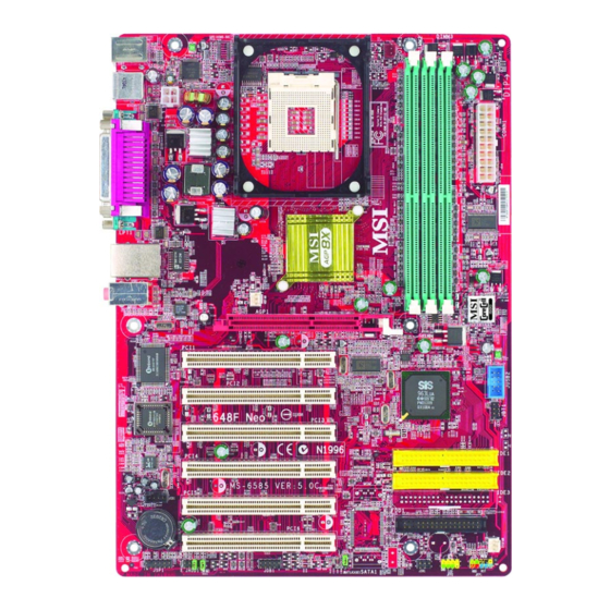
Page 11: Mainboard Layout
W83697HF PCI Slot 2 963L JBT1 PCI Slot 3 PCI Slot 4 IDE 1 Codec IDE 2 JCD1 PCI Slot 5 PCI Slot 6 BATT FDD1 SYSFAN JSP1 JAUD1 JDB1 JIR1 JBAT1 JFP2 JFP1 648F Neo (MS-6585 v5.X) ATX Mainboard... -
Page 12: Msi Special Features
Getting Started MSI Special Features S-Bracket (Optional) S-Bracket is a bracket which provides 2 SPDIF jacks for digital audio transmission and 2 analog Line-Out connectors for additional 4-channel ana- log audio output. With the S-Bracket, your system will be able to perform 6- channel audio operation for wonderful surround sound effect, or connect to Sony &... -
Page 13: Core Center
MS-6585 ATX Mainboard Core Center The Core Center is a new utility you can find in the CD-ROM disk. The utility is just like your PC doctor that can detect, view and adjust the PC hardware and system status during real time operation. In the left side it shows the current system status including the Vcore, 3.3V, +5V and 12V. - Page 14 Getting Started Left-side: Current system status In the left sub-menu, you can configure the settings of FSB, Vcore, Memory Voltage and AGP Voltage by clicking the radio button in front of each item and make it available (the radio button will be lit as yellow when selected), use the “+”...
-
Page 15: Live Bios™/Live Driver
BIOS/drivers online so that you don’t need to search for the correct BIOS/driver version throughout the Web site. To use the function, you need to install the “MSI Live Update 2” application. After installation, the “MSI Live Update 2” icon (as shown on the right) will appear on the screen. -
Page 16: Live Monitor
Live Monitor™ The Live Monitor™ is a tool used to schedule the search for the latest BIOS/drivers version on the MSI Web site. To use the function, you need to install the “MSI Live Update 2” application. After installation, the “MSI Live Monitor” icon (as shown on the right) will appear on the screen. -
Page 17: D-Bracket™ 2 (Optional)
MS-6585 ATX Mainboard D-Bracket™ 2 (Optional) D-Bracket™ 2 is a USB bracket integrating four Diagnostic LEDs, which use graphic signal display to help users understand their system. The LEDs provide up to 16 combinations of signals to debug the system. The 4 LEDs can detect all problems that fail the system, such as VGA, RAM or other failures. - Page 18 Getting Started D-Bracket™ 2 Description Processor Initialization - This will show information regarding the processor (like brand name, system bus, etc…) Testing RTC (Real Time Clock) Initializing Video Interface - This will start detecting CPU clock, checking type of video onboard.
-
Page 19: Color Management
MS-6585 ATX Mainboard Color Management MSI has an unified color management rule for some connectors on the mainboards, which helps you to install the memory modules, expansion cards and other peripherals devices more easily and conveniently. Memory DDR DIMMs: light green... -
Page 20: Chapter 2. Hardware Setup
Hardware Setup Chapter 2. Hardware Setup Hardware Setup This chapter tells you how to install the CPU, memory modules, and expansion cards, as well as how to setup the jumpers on the mainboard. Also, it provides the instructions on connecting the peripheral devices, such as the mouse, keyboard, etc. -
Page 21: Quick Components Guide
MS-6585 ATX Mainboard Quick Components Guide JPW1, p.2-9 CPU, p.2-3 CPUFAN, p.2-16 CONN1, p.2-9 Back Panel I/O, p.2-10 NBFAN, p.2-16 DDR DIMMs, p.2-7 AGP Slot, p.2-27 JUSB2, p.2-22 JBT1, p.2-23 PCI Slots, p.2-27 IDE1, IDE2, p.2-18 JCD1, p.2-20 FDD1, p.2-15 SYSFAN, p.2-16 JSP1, p.2-20 JFP1, p.2-17... -
Page 22: Central Processing Unit: Cpu
DDR 266 DDR 333 DDR 400 400 MHz 533 MHz 800 MHz MSI Reminds You... Overheating Overheating will seriously damage the CPU and system, always make sure the cooling fan can work properly to protect the CPU from overheating. Overclocking This motherboard is designed to support overclocking. -
Page 23: Cpu Installation Procedures For Socket 478
MS-6585 ATX Mainboard CPU Installation Procedures for Socket 478 Please turn off the power and unplug the power cord before Open Lever installing the CPU. Pull the lever sideways away Sliding 90 degree Plate from the socket. Make sure to raise the lever up to a 90- degree angle. -
Page 24: Installing The Cpu Fan
Hardware Setup Installing the CPU Fan As processor technology pushes to faster speeds and higher performance, thermal management becomes increasingly important. To dissipate heat, you need to attach the CPU cooling fan and heatsink on top of the CPU. Follow the instructions below to install the Heatsink/Fan: Locate the CPU and its retention Position the heatsink onto the reten- mechanism on the motherboard. - Page 25 MS-6585 ATX Mainboard Connect the fan power cable from the mounted fan to the 3-pin fan power connector on the board. fan power cable NOTES...
-
Page 26: Memory
168-pin DIMM modules used by SDR SDRAM. High memory bandwidth makes DDR an ideal solution for high performance PC, workstations and servers. MSI Reminds You... If you want to install PC3200/DDR400 module, you can only install 2 DIMMs at the most, no matter you install single-side or double-... -
Page 27: Ddr Dimm Module Combination
2. Insert the DIMM memory module vertically into the DIMM slot. Then push it in until the golden finger on the memory module is deeply inserted in the socket. MSI Reminds You... You can barely see the golden finger if the module is properly inserted in the socket. -
Page 28: Power Supply
This 12V power connector is used to provide power to the CPU. JPW1 CONN1 CONN1 Pin Definition JPW1 Pin Definition SIGNAL SIGNAL SIGNAL 3.3V 3.3V 3.3V -12V PS_ON PW_OK 5V_SB MSI Reminds You... Power supply of 300 (and up) watt is highly recommended for system stability. -
Page 29: Back Panel
MS-6585 ATX Mainboard Back Panel The back panel provides the following connectors: Parallel (Optional) Mouse USB Ports L-in Keyboard USB Ports COM B COM A L-out Mouse Connector The mainboard provides a standard PS/2 ® mouse mini DIN connector ® ®... -
Page 30: Keyboard Connector
Hardware Setup Keyboard Connector ® The mainboard provides a standard PS/2 keyboard mini DIN connector ® ® for attaching a PS/2 keyboard. You can plug a PS/2 keyboard directly into this connector. Pin Definition SIGNAL DESCRIPTION Keyboard DATA Keyboard DATA No connection Ground Keyboard Clock... -
Page 31: Serial Port Connectors: Com A & Com B
MS-6585 ATX Mainboard Serial Port Connectors: COM A & COM B The mainboard offers two 9-pin male DIN connectors as serial port COM A & COM B. The ports are 16550A high speed communication ports that send/receive 16 bytes FIFOs. You can attach a serial mouse or other serial devices directly to the connectors. -
Page 32: Parallel Port Connector: Lpt1
Hardware Setup Parallel Port Connector: LPT1 The mainboard provides a 25-pin female centronic connector as LPT. A parallel port is a standard printer port that supports Enhanced Parallel Port (EPP) and Extended Capabilities Parallel Port (ECP) mode. Pin Definition SIGNAL DESCRIPTION STROBE Strobe... -
Page 33: Audio Port Connectors
1/8” Stereo Audio Connectors Line In Line Out MSI Reminds You... The mainboard offers 6-channel audio operation and can turn rear audio connectors from 2-channel to 4-/6-channel audio. For more information on 6-channel audio operation, please refer to Appendix A: Using 4- or 6-Channel Audio Function. -
Page 34: Connectors
Hardware Setup Connectors The mainboard provides connectors to connect to FDD, IDE HDD, case, LAN, USB Ports, IR module and CPU/System/Power Supply FAN. Floppy Disk Drive Connector: FDD1 The mainboard provides a standard floppy disk drive connector that supports 360K, 720K, 1.2M, 1.44M and 2.88M floppy disk types. FDD1 2-15... -
Page 35: Fan Power Connectors: Cpufan/Sysfan/Nbfan
NBFAN SENSOR +12V SYSFAN MSI Reminds You... 1. Always consult the vendors for proper CPU cooling fan. 2. CPUFAN supports the fan control. You can install the Core Center utility that will automatically control the CPU fan speed according to the actual CPU temperature. -
Page 36: Front Panel Connectors: Jfp1 & Jfp2
Hardware Setup Front Panel Connectors: JFP1 & JFP2 The mainboard provides two front panel connectors for electrical ® connection to the front panel switches and LEDs. JFP1 is compliant with Intel Front Panel I/O Connectivity Design Guide. Power Power Switch JFP1 Reset Switch... -
Page 37: Hard Disk Connectors: Ide1 & Ide2
IDE2 (Secondary IDE Connector) IDE2 can also connect a Master and a Slave drive. MSI Reminds You... If you install two hard disks on cable, you must configure the second drive to Slave mode by setting its jumper. Refer to the hard disk documentation supplied by hard disk vendors for jumper setting instructions. -
Page 38: Front Panel Audio Connector: Jaud1
Left channel audio signal to front panel AUD_RET_L Left channel audio signal return from front panel MSI Reminds You... If you don’t want to connect to the front audio header, pins 5 & 6, 9 & 10 have to be jumpered in order to have signal output directed to the rear audio ports. -
Page 39: Cd-In Connector: Jcd1
MS-6585 ATX Mainboard CD-In Connector: JCD1 The connector is for CD-ROM audio connector. S-Bracket (SPDIF) Connector: JSP1 (Optional) The connector allows you to connect a S-Bracket for Sony & Philips Digital Interface (SPDIF). The S-Bracket offers 2 SPDIF jacks for digital audio transmission (one for optical fiber connection and the other for coaxial), and 2 analog Line-Out jacks for 4-channel audio output. - Page 40 Hardware Setup JSP1 Pin Definition SIGNAL DESCRIPTION SIGNAL DESCRIPTION VCC5 VCC 5V VDD3 VDD 3.3V SPDFO S/PDIF output (No Pin) Ground SPDFI S/PDIF input LFE-OUT Audio bass output SOUT-R Audio right surrounding output CET-OUT Audio center output 10 SOUT-L Audio left surrounding output Ground Ground Optional S-Bracket...
-
Page 41: Front Usb Connector: Jusb2
MS-6585 ATX Mainboard Front USB Connector: JUSB2 The mainboard provides one USB 2.0 pin headers JUSB2 that is compliant ® with Intel I/O Connectivity Design Guide. USB 2.0 technology increases data transfer rate up to a maximum throughput of 480Mbps, which is 40 times faster than USB 1.1, and is ideal for connecting high-speed USB interface peripherals such as USB HDD, digital cameras, MP3 players, printers, modems and the like. -
Page 42: Bluetooth Connector: Jbt1 (Optional)
D- (USB signal) Do not remove, when using bluetooth MSI Reminds You... Because the bluetooth connector shares the USB interface with blue-colored USB2.0 connector, one of the USB2.0 port (see instruction on the cable) will not function when you attach a bluetooth module to this connector. -
Page 43: D-Bracket™ 2 Connector: Jdb1 (Optional)
MS-6585 ATX Mainboard D-Bracket™ 2 Connector: JDB1 (Optional) The mainboard comes with a JDB1 connector for you to connect to D- Bracket™ 2. D-Bracket™ 2 is a USB Bracket that supports both USB1.1 & 2.0 spec. It integrates four LEDs and allows users to identify system problem through 16 various combinations of LED signals. -
Page 44: Irda Infrared Module Header: Jir1
Hardware Setup IrDA Infrared Module Header: JIR1 The connector allows you to connect to IrDA Infrared module. You must configure the setting through the BIOS setup to use the IR function. JIR1 is ® compliant with Intel Front Panel I/O Connectivity Design Guide. JIR1 Pin Definition Signal VCC5... -
Page 45: Jumpers
JBAT1 Clear Data Keep Data MSI Reminds You... You can clear CMOS by shorting 2-3 pin while the system is off. Then return to 1-2 pin position. Avoid clearing the CMOS while the system is on; it will damage the mainboard. -
Page 46: Slots
Hardware Setup Slots The motherboard provides one AGP slot, and five 32-bit PCI bus slots. AGP Slot PCI Slots AGP (Accelerated Graphics Port) Slot The AGP slot allows you to insert the AGP graphics card. AGP is an interface specification designed for the throughput demands of 3D graphics. It introduces a 66MHz, 32-bit channel for the graphics controller to directly access main memory. -
Page 47: Pci Interrupt Request Routing
MS-6585 ATX Mainboard PCI Interrupt Request Routing The IRQ, acronym of interrupt request line and pronounced I-R-Q, are hardware lines over which devices can send interrupt signals to the microprocessor. The PCI IRQ pins are typically connected to the PCI bus INT A# ~ INT D# pins as follows: Order 1 Order 2... -
Page 48: Chapter 3. Bios Setup
BIOS Setup Chapter 3. BIOS Setup BIOS Setup This chapter provides information on the BIOS Setup program and allows you to configure the system for optimum use. You may need to run the Setup program when: An error message appears on the screen during the system booting up, and requests you to run SETUP. -
Page 49: Entering Setup
MS-6585 ATX Mainboard Entering Setup Power on the computer and the system will start POST (Power On Self Test) process. When the message below appears on the screen, press <DEL> key to enter Setup. DEL:Setup F11:Boot Menu F12:Network boot TAB:Logo If the message disappears before you respond and you still wish to enter Setup, restart the system by turning it OFF and On or pressing the RESET button. -
Page 50: Control Keys
BIOS Setup Control Keys <↑> Move to the previous item <↓> Move to the next item <←> Move to the item in the left hand <→> Move to the item in the right hand <Enter> Select the item <Esc> Jumps to the Exit menu or returns to the main menu from a submenu <+/PU>... -
Page 51: The Main Menu
MS-6585 ATX Mainboard The Main Menu Once you enter AMIBIOS NEW SETUP UTILITY, the Main Menu will appear on the screen. The Main Menu displays twelve configurable functions and two exit choices. Use arrow keys to move among the items and press <Enter>... - Page 52 BIOS Setup Integrated Peripherals Use this menu to specify your settings for integrated peripherals. PC Health Status This entry shows your PC health status. Frequency/Voltage Control Use this menu to specify your settings for frequency/voltage control. Set Supervisor Password Use this menu to set Supervisor Password. Set User Password Use this menu to set User Password.
-
Page 53: Standard Cmos Features
MS-6585 ATX Mainboard Standard CMOS Features The items inside STANDARD CMOS SETUP menu are divided into 9 categories. Each category includes none, one or more setup items. Use the arrow keys to highlight the item you want to modify and use the <PgUp> or <PgDn>... - Page 54 BIOS Setup Primary/Secondary IDE Master/Slave Press PgUp/<+> or PgDn/<-> to select the hard disk drive type. The specification of hard disk drive will show up on the right hand according to your selection. Type Select how to define the HDD parameters Cylinders Enter cylinder number Heads...
-
Page 55: Advanced Bios Features
MS-6585 ATX Mainboard Advanced BIOS Features Quick Boot Setting the item to Enabled allows the system to boot within 5 seconds since it will skip some check items. Available options: Enabled, Disabled. Full Screen LOGO Show This item enables you to show the company logo on the bootup screen. Settings are: Enabled Shows a still image (logo) on the full screen at boot. - Page 56 BIOS Setup 1st/2nd/3rd Boot Device The items allow you to set the sequence of boot devices where AMIBIOS attempts to load the operating system. The settings are: IDE-0 The system will boot from the first HDD. IDE-1 The system will boot from the second HDD. IDE-2 The system will boot from the third HDD.
- Page 57 Disabled Disable this sequence. MSI Reminds You... Available settings for “1st/2nd/3rd Boot Device” vary depend- ing on the bootable devices you have installed. For example, if you did not install a floppy drive, the setting “Floppy” does not show up.
- Page 58 BIOS Setup Seek Floopy This setting causes the BIOS to search for floppy disk drives at boot time. When enabled, the BIOS will activate the floppy disk drives during the boot process: the drive activity light will come on and the head will move back and forth once.
- Page 59 MS-6585 ATX Mainboard MSI Reminds You... Enabling the functionality of Hyper-Threading Technology for your computer system requires ALL of the following platform Components: ® ® *CPU: An Intel Pentium 4 Processor with HT Technology; *Chipset: A chipset that supports HT Technology;...
-
Page 60: Advanced Chipset Features
BIOS Setup Advanced Chipset Features MSI Reminds You... Change these settings only if you are familiar with the chipset. CAS Latency The field controls the CAS latency, which determines the timing delay before SDRAM starts a read command after receiving it. Setting options: By SPD, 3T, 2.5T, 2T. - Page 61 MS-6585 ATX Mainboard System Performance This setting particularly provided by SiS gives the proper suggestion for user for timing setting. Setting options: Enabled, Disabled. Enhance DDR400 Timing This setting enables you to enhance the DDR 400 timing performance, which is available when the System Performance is set to Enabled. Setting options: Enabled, Disabled.
-
Page 62: Power Management Features
BIOS Setup Power Management Features MSI Reminds You... S3-related functions described in this section are available only when your BIOS supports S3 sleep mode. APCI Standby State This item secifies the power saving modes for ACPI function. If your operating... - Page 63 MS-6585 ATX Mainboard Initalize VGA BIOS By S3 Selecting Enabled will make BIOS call VGA BIOS to initialize the VGA card when system wakes up (resume) from S3 state. The system resume time is shortened if you disable the function, but system will need AGP driver to initialize the card.
- Page 64 00 ~ 23 Alarm Minute 00 ~ 59 Alarm Second 00 ~ 59 MSI Reminds You... If you have changed this setting, you must let the system boot up until it enters the operating system, before this function will work. 3-17...
-
Page 65: Pnp/Pci Configurations
MS-6585 ATX Mainboard PNP/PCI Configurations This section describes configuring the PCI bus system and PnP (Plug & Play) feature. PCI, or Peripheral Component Interconnect, is a system which allows I/O devices to operate at speeds nearing the speed the CPU itself uses when communicating with its special components. - Page 66 BIOS Setup Primary Graphics Adaptor This setting specifies which VGA card is your primary graphics adapter. Setting options are: The system initializes the installed AGP card first. If the AGP card is not available, it will initialize the PCI VGA card.
- Page 67 MS-6585 ATX Mainboard Set IRQs to PCI or ISA Press <Enter> to enter the sub-menu and the following screen appears: IRQ 3/4/5/7/9/10/11/14/15 These items specify the bus where the specified IRQ line is used. The settings determine if AMIBIOS should remove an IRQ from the pool of available IRQs passed to devices that are configurable by the system BIOS.
-
Page 68: Integrated Peripherals
BIOS Setup Integrated Peripherals Please note that the options showed on your BIOS might be different depending on the motherboard you buy. OnBoard PCI IDE This setting controls the onboard PCI IDE controllers. Setting options: Disabled, Primiary, Secondary, Both. USB Function This setting is used to enable/disable the onboard USB function. - Page 69 MS-6585 ATX Mainboard AC97 Audio This item is used to enable or disable the onboard AC’97 (Audio Codec’97) feature. Selecting Auto allows the mainboard to detect whether an audio device is used. If an audio device is detected, the onboard AC’97 controller will be enabled;...
- Page 70 BIOS Setup Parallel Port These items specify the base I/O port addresses of the onboard parallel port. Selecting Auto allows AMIBIOS to automatically determine the correct base I/O port address. Settings: Auto, 378h, 278h, 3BCh and Disabled. Parallel Port Mode This item selects the operation mode for the onboard parallel port: ECP, Normal, Bi-Dir or EPP.
-
Page 71: Pc Health Status
MS-6585 ATX Mainboard PC Health Status This section shows the status of your CPU, fan, overall system status, etc. Monitor function is available only if there is hardware monitoring mechanism onboard. CPU/SYSTEM Temperature, CPU FAN Speed, Vcore, +3.3V, +5.0V, +12V, -12V, -5.0V, Battery These items display the current status of all of the monitored hardware devices/ components such as CPU voltages, temperatures and all fans’... -
Page 72: Frequency/Voltage Control
BIOS Setup Frequency/Voltage Control Use this menu to specify your settings for frequency/voltage control. Auto Detect CPU and DRAM Freq This item is used to auto detect the frequency of CPU and DRAM. Settings: Enabled and Disabled. CPU Frequency This setting shows the current CPU Front Side Bus clock frequency. CPU/DRAM Frequency Ratio This setting controls the ratio of CPU FSB Clock &... - Page 73 MS-6585 ATX Mainboard CPU Ratio This setting controls the multiplier that is used to determine the internal clock speed of the processor relative to the external or motherboard clock speed. Spread Spectrum When the motherboard’s clock generator pulses, the extreme values (spikes) of the pulses creates EMI (Electromagnetic Interference).
- Page 74 BIOS Setup MSI Reminds You... The settings shown in different color in CPU Vcore Adjust (V), DRAM Vcore Adjust (V) and AGP Voltage Adjust (V) helps to verify if your setting is proper for your system. White: Safe setting. Yellow: High performance setting.
-
Page 75: Set Supervisor/User Password
FEATURES menu. If the PASSWORD CHECK option is set to Always, the password is required both at boot and at entry to Setup. If set to Setup, password prompt only occurs when you try to enter Setup. MSI Reminds You... About Supervisor Password & User Password: Supervisor password: Can enter and change the settings of the setup menu. -
Page 76: Load Optimal/High Performance Defaults
Pressing ‘Enter’ loads the default values that are factory settings for stable system performance. MSI Reminds You... The option is for power or overclocking users only. Use of high performance defaults will tighten most timings to increase the system performance. Therefore, a high-end system configuration is a must, which means you need high-quality VGA adapter, RAM and so on. -
Page 77: Appendix: Using 4- Or 6-Channel Audio Function
Using 4- or 6-Channel Audio Function Appendix: Using 4- or 6-Channel Audio Function The motherboard is equipped with Realtek ALC655 chip, which provides support for 6-channel audio output, including 2 Front, 2 Rear, 1 Center and 1 Subwoofer channel. ALC655 allows the board to attach 4 or 6 speakers for better surround sound effect. -
Page 78: Installing The Audio Driver
1. Insert the companion CD into the CD-ROM drive. The setup screen will automatically appear. 2. Click Realtek AC97 Audio Driver. Click here MSI Reminds You... The AC97 Audio Configuration software utility is under continuous update to enhance audio applications. Hence, the... - Page 79 Using 4- or 6-Channel Audio Function 3. Click Next to start installing files into the system. Click here 4. Click Finish to restart the system. Select this option Click here...
-
Page 80: Using 4- Or 6-Channel Audio Function
MS-6585 ATX Mainboard Using 4- or 6-Channel Audio Function After installing the audio driver, you are able to use the 4-/6-channel audio feature now. To enable 4- or 6-channel audio operation, first connect 4 or 6 speakers to the appropriate audio connectors, and then select 4- or 6- channel audio setting in the software utility. - Page 81 Using 4- or 6-Channel Audio Function audio devices you wish to use for audio outputs. The instructions shown on the Speaker Configuration screen may vary depending on how you set the options of No. of Speaker and Default Phonejack. To ensure proper hardware installation, connect your speakers to the correct phonejacks in accordance with the setting in software utility.
- Page 82 MS-6585 ATX Mainboard 7. On the S/PDIF-In tab, it shows the current status. Since this mainboard does not support the S/PDIF-in function, no selection is available. 8. On the S/PDIF-Out tab, you may slelect the format of SPDIF out.
- Page 83 Using 4- or 6-Channel Audio Function 9. On the Equalizer tab, you can adjust each volume of the speaker for current playing digital sound sources.
- Page 84 Coaxial SPDIF jack Coaxial SPDIF jack Back Panel S-Bracket MSI Reminds You... When any Multi-Channel Audio Mode is selected, you may also connect your speakers to the Optical or Coaxial SPDIF phone jack on the S-Bracket to exprience digital surround sound effect.
- Page 85 Using 4- or 6-Channel Audio Function 4-Channel Mode for 4-Speaker Output When this mode is selected, plug the two front speakers to the Line Out connector on the back panel, and the other two rear speakers to the Line Out connector on the S-Bracket. Refer to the following diagram and caption for the function of each phone jack on the back panel and S-Bracket when 4-Channel mode is selected.
- Page 86 Line Out (Rear channels) Back Panel S-Bracket MSI Reminds You... If the Center and Subwoofer speaker exchange their audio channels when you play video or music on the computer, a converter may be required to exchange center and subwoofer audio signals.
- Page 87 Using 4- or 6-Channel Audio Function Digital Audio Output When any Multi-Channel Audio Function mode is selected, you may also connect your speakers to the Optical or Coaxial SPDIF phone jack on the S-Bracket to exprience digital surround sound effect. Remove the plug from the optical SPIDF phone jack before inserting the fiber-optic cable, and read the following diagram and captions for the function of each phone jack on the S-Bracket.
-
Page 88: Using The Back Panel Only
MS-6585 ATX Mainboard Using the Back Panel only In addition to a default 2-channel analog audio output function, the audio connectors on the Back Panel also provide 4- or 6-channel analog audio output function if a proper setting is made in the software utility. Read the following steps to have the Multi-Channel Audio Function properly set in the software utility, and have your speakers correctly connected to the Back Panel. - Page 89 Using 4- or 6-Channel Audio Function Connecting the Speakers When you have set the Multi-Channel Audio Function mode properly in the software utility, connect your speakers to the correct phone jacks in accordance with the setting in software utility. 2-Channel Mode for Stereo-Speaker Output Refer to the following diagram and caption for the function of each phone jack on the back panel when 2-Channel Mode is selected.
- Page 90 MS-6585 ATX Mainboard 4-Channel Mode for 4-Speaker Output The audio jacks on the back panel always provide 2-channel analog audio output function, however these audio jacks can be transformed to 4- or 6- channel analog audio jacks by selecting the corresponding multi-channel operation from No.
- Page 91 * Both Line In and MIC function are converted to Line Out function when 4- Channel Mode for 6-Speaker Output is selected. MSI Reminds You... If the Center and Subwoofer speaker exchange their audio channels when you play video or music on the computer, a converter may be required to exchange center and subwoofer audio signals.
-
Page 92: Testing The Connected Speakers
Rear Left Subwoofer Select this function MSI Reminds You... 6 speakers appear on the “Speaker Test” window only when you select “6-Channel Mode” in the “No. of Speakers” column. If you select “4-Channel Mode”, only 4 speakers appear on the window. - Page 93 Using 4- or 6-Channel Audio Function 4. While you are testing the speakers in 6-Channel Mode, if the sound coming from the center speaker and subwoofer is swapped, you should select Swap Center/Subwoofer Output to readjust these two channels. A-17...
-
Page 94: Playing Karaok
MS-6585 ATX Mainboard Playing KaraOK The KaraOK function will automatically remove human voice (lyrics) and leave melody for you to sing the song. Note that this function applies only for 2-channel audio operation. Playing KaraOK 1. Click the audio icon from the window tray at the lower-right corner of the screen. -
Page 95: Troubleshooting
Troubleshooting Troubleshooting Troubleshooting How do I know that the product that I have is from MSI? All MSI product starts with the character MS-XXXX or Marketing Name (MS-XXXX) wherein XXXX refers to numbers. You should be able to find the Model number in between the PCI slots. For Example: MS-6368... - Page 96 If problem still persists, you would need to purchase new BIOS chip from Websites like www.flashbios.org where you can order a new BIOS or you can also contact MSI office near your place to purchase new BIOS chip. Please refer to http://www.msi.com.tw/html/contact/contact.htm My motherboard BIOS sticker is "Phoenix BIOS", but when I boot up...
- Page 97 CPU type 3. For Optical product firmware, refer to http://www.msi.com.tw/program/ support/driver/dvr/spt_dvr_list.php?part=4 Where can I find MSI developed software such as Fuzzy Logic or PC Alert? Refer to http://www.msi.com.tw/program/support/software/swr/ spt_swr_list.php Where can I find the manual? 1.
- Page 98 2. Try to clear the CMOS. If problem still persists, ask your reseller for new BIOS chip or contact one of MSI office near your place for new BIOS chip. Please refer to http://www.msi.com.tw/contact/main.htm Should I update my BIOS, once a new BIOS is released? 1.
- Page 99 3. For Server motherboard, refer to http://www.msi.com.tw/program/sup- port/driver/dvr/spt_dvr_list.php?part=3 4. For Optical product firmware, refer to http://www.msi.com.tw/program/ support/driver/dvr/spt_dvr_list.php?part=4 5. For MSI special product like bluetooth or TV tuner, refer to http:// www.msi.com.tw/program/support/driver/dvr/spt_dvr_list.php? part=5 How can I know what CPU does my motherboard support? 1.
- Page 100 How can I find MSI distributor in my country? Refer to http://www.msi.com.tw/program/contact/where2buy/. Select the country & you will find MSI distributor in that country. If in case you cannot find the country listed, then it means MSI still don’t have dis-...
- Page 101 - Move the PCI card to different PCI slots - Update the card BIOS or drivers - Update the motherboard BIOS What should I do if my MSI VGA card have compatibility issue with another brand of motherboard? Update the video driver...
-
Page 102: Glossary
Glossary Glossary Glossary ACPI (Advanced Configuration & Power Interface) This power management specification enables the OS (operating system) to control the amount of power given to each device attached to the computer. Windows 98/98SE, Windows 2000 and Windows ME can fully support ACPI to allow users managing the system power flexibly. - Page 103 MS-6585 ATX Mainboard contents of frequently accessed RAM locations and the addresses where these data items are stored. Chipset A collection of integrated chips designed to perform one or more related functions. For example, a modem chipset contains all the primary circuits for transmitting and receiv- ing data;...
- Page 104 Glossary ECC Memory (Error Correcting Code Memory) A type of memory that contains special circuitry for testing the accuracy of data and correcting the errors on the fly. EEPROM Acronym for Electrically Erasable Programmable Read-Only Memory. An EEPROM is a special type of PROM that can be erased by exposing it to an electrical charge. Like other types of PROM, EEPROM retains its contents even when the power is turned off.
- Page 105 MS-6585 ATX Mainboard IDE (Integrated Drive Electronics) A type of disk-drive interface widely used to connect hard disks, CD-ROMs and tape drives to a PC, in which the controller electronics is integrated into the drive itself, eliminating the need for a separate adapter card. The IDE interface is known as the ATA (AT Attachment) specification.
- Page 106 Glossary LBA (Logical Block Addressing) Logical block addressing is a technique that allows a computer to address a hard disk larger than 528 megabytes. A logical block address is a 28-bit value that maps to a specific cylinder-head-sector address on the disk. 28 bits allows sufficient variation to specify addresses on a hard disk up to 8.4 gigabytes in data storage capacity.
- Page 107 MS-6585 ATX Mainboard PS/2 Port A type of port developed by IBM for connecting a mouse or keyboard to a PC. The PS/2 port supports a mini DIN plug containing just 6 pins. Most modern PCs equipped with PS/2 ports so that the special port can be used by another device, such as a modem.
Need help?
Do you have a question about the 648F Neo and is the answer not in the manual?
Questions and answers