
Related Manuals for Bosch TSTBM3H2CPH6W-A


Summary of Contents for Bosch TSTBM3H2CPH6W-A
-
Page 1: Installation Manual
Installation Manual Series ttStBM3H2CPH6W-A tHerMoStAt And WireleSS CoMMuniCAting BASe Module TSTBM3H2CPH6W-A 6 720 220 376 Revised 02-13... -
Page 2: Table Of Contents
Understanding Swing And Staging ..............22 HUM Terminal ...................... 22 DHM Terminal ...................... 22 Humidification / Dehumidification Recommendation for Bosch Heat Pump ..23 Setting Target Humidity Setpoint ................ 23 Ambient Humidity Display ................... 23 Recommended Cooling Settings: ................ 24 Set Time ...................... -
Page 3: Thermostat Applications Guide
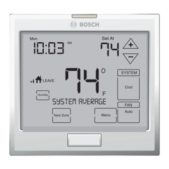
TSTBM3H2CPH6W-A thermostat Quick reference the tStBM3H2CPH6W-A offers the tHerMoStAt QuiCK referenCe following: getting to know your thermostat • 3 stages of heating • 2 stages of cooling • Temperature averaging with remote sensors • Wireless control • 5+1+1 & 7 Day Programmable... -
Page 4: Installation Tips
All Bosch thermostats use the same • Close to hot or cold air ducts universal magnetic badge. Contact your local Bosch distributor to learn more about our Pick an installation location that is easy for free private label program. the user to access. The temperature of the... -
Page 5: Base Module-Basement Installation
Wireless range the terminal connections on the thermostat that is being replaced. In some cases the wiring Range between the TSTBM3H2CPH6W-A and the connections will not be color coded. For base module is up to 100 feet with no obstructions... -
Page 6: Thermostat Installation And Wiring
Caution flat wall with the drywall anchors flush to the wall. Using the screws and drywall anchors that were provided with the thermostat. The TSTBM3H2CPH6W-A can be battery powered only if used as a stand-alone Caution thermostat solution. The TSTBM3H2CPH6W-A... -
Page 7: Mount Thermostat And Base Module
Mount thermostat And Base Module TSTBM3H2CPH6W-A Mount tHerMoStAt And BASe Module Align the 4 tabs on the subbase with corresponding slots on the back of the thermostat or base module. Then push gently until the thermostat or base module. To insure a solid fit between the thermostat and the subbase: 1. -
Page 8: Wiring Schematicss
TSTBM3H2CPH6W-A Wiring Schematics tyPiCAl Wiring SCHeMAtiCS WireleSS WitH BASe Module tStBM3H2CPH6W-A 3H/2C HEAT PUMP TSTBM3H2CPH6W-A THERMOSTAT PACKAGED BASE MODULE HEAT PUMP W2/E W1/E 2H/1C HEAT PUMP TSTBM3H2CPH6W-A THERMOSTAT PACKAGED BASE MODULE HEAT PUMP W2/E W1/E 6 720 220 376 Subject to change without prior notice... - Page 9 Wiring Schematics TSTBM3H2CPH6W-A 3H/2C SPLIT HEAT PUMP FAN COIL / AIR COMPRESSOR BASE MODULE HANDLER SECTION W2/E TSTBM3H2CPH6W-A THERMOSTAT W1/E 3H/2C HEAT PUMP WITH GAS/OIL FURNACE HEAT BACKUP BASE MODULE FAN COIL / FURNACE COMPRESSOR SECTION Y/Y1 W/W1 TSTBM3H2CPH6W-A THERMOSTAT...
- Page 10 10 TSTBM3H2CPH6W-A Wiring Schematics JUMP "E" & "W2" AT THE TSTBM3H2CPH6W-A THERMOSTAT WHEN THE HEAT PUMP EQUIPMENT DOES NOT HAVE AN EMERGENCY HEAT TERMINAL TSTBM3H2CPH6W-A THERMOSTAT PACKAGED BASE MODULE HEAT PUMP W1/E 2H/2C AIR CONDITIONING W/ ELECTRIC HEAT BACKUP BASE MODULE...
- Page 11 Wiring Schematics TSTBM3H2CPH6W-A UNIT WITH ACTIVE OR PASSIVE DEHUMIDIFICATION AND HUMIDIFICATION RELAY COMMON FROM HVAC EQUIPMENT BASE MODULE HVAC EQUIPMENT PASSIVE / ACTIVE DEHUMIDIFICATION HUMIDIFIER EQUIPMENT HUMIDIFIER SOLENOID Revised 02-13 Subject to change without prior notice 6 720 220 376...
-
Page 12: Terminal Designations On Base Module
- Bosch Water Source Heat Pumps utilize “O” type reversing valve operation. If your heat pump utilizes “B” type reversing valve operation, substitute the wiring for the “O”... -
Page 13: Establishing Communication Between Tstbm3H2Cph6W-A
(Base module must be powered by 24V. Blue led will be continuously on when 24V power is present.) 2. Hold the light key of the TSTBM3H2CPH6W-A for 10 seconds, the Blue led on the base module will stop flashing after communication... -
Page 14: Technician Setup Menu
NEXT STEP or PREV STEP key to DO NOT hold the light button on the move from one option to another. TSTBM3H2CPH6W-A for more than 10 seconds after Step 2 above has been completed. Only press DONE key when you want to exit Caution the Technician Setup options. - Page 15 Setup Menu TSTBM3H2CPH6W-A tech Setup Steps factory lCd will show Adjustment options default Settings filter This feature will flash filt in You can adjust the filter change the display after the elapsed reminder from off to 2000 hours of...
- Page 16 Setup Menu 16 TSTBM3H2CPH6W-A To lock the keypad, hold down the keys for 3 seconds. You will see a lock in the display. To unlock the keypad hold down the keys for 3 seconds. tech Setup Step (Continued from the previous page)
- Page 17 Setup Menu TSTBM3H2CPH6W-A tech Setup Step (Continued from the previous page) factory lCd will show Adjustment options default Settings Program You can configure this Use the – keys to select 7d thermostat to have a 7 day options for 7 day, 5d for 5+1+1, or 0d for program, a 5+1+1 program or nonprogammable.
- Page 18 TSTBM3H2CPH6W-A thermostat. enable the balance point tech setup option. This allows for 5 sensing points (zones). For Example: The local ( TSTBM3H2CPH6W-A) plus four TSTBM- RRS--TW-A sensors enables 5 sensing points. See the tech setup menu below to activate this feature.
- Page 19 Sensor TW-A. Selecting yeS requires an indoor remote sensor TSTBM- the TSTBM3H2CPH6W-A master RRS--TW-A. When yeS is selected thermostat to be powered with the thermostat is able to connect 24v on C and r terminals.
-
Page 20: Balance Point
20 TSTBM3H2CPH6W-A technician Setup Menu Balance Point: chooses either the heat pump or gas furnace. For Example: The system operates differently when a balance A balance point setting of 30ºF will turn on only the heat point is used on a dual fuel system. The balance pump above 30ºF and only the gas furnace below 30ºF. - Page 21 Setup Menu TSTBM3H2CPH6W-A tech Setup Step (Continued from the previous page) factory lCd will show Adjustment options default Settings dehumidify This feature forces the A/C to run Use the – keys select yeS or longer to remove humidity when with AC needed.
-
Page 22: Understanding Swing And Staging
HuM and dHM terminals underStAnding SWing And StAging Temp Actions 71°F 1st Stage Off All Bosch thermostats have adjustable swings. Cycling your HVAC system is a balance between user 70°F Set point comfort and equipment efficiency. Equipment wear 69°F 1st Stage On / 2nd Stage Off and tear is also a consideration. -
Page 23: Humidification / Dehumidification Recommendation For Bosch Heat Pump
“D” terminal, the fan motor will slow down to better dehumidify the air by over cooling. Humidification 1. Select HUM Terminal #1. This will work with Bosch Humidifier Series and replace the manual humidistat. Dehumidification 1. Enable Cool-to-dehumidify feature from the Tech Menu Setup 2. -
Page 24: Recommended Cooling Settings
All other sensors will be ProgrAMMing ignored. All programmable Bosch thermostats are shipped with 4. Time is flashing. Use the [+] or [–] key to make an energy saving pre-program. You can customize this your time selection for the weekday WAKe time default program by following the Set Program Schedule period. - Page 25 HuM and dHM terminals TSTBM3H2CPH6W-A factory default Program Day of the Events Time Setpoint Setpoint Zone (TSTBM-RRS--TW-A Week Events Time Temperature (Cool) Temperature Sensor is Temperature (Heat) connected) 6 a.m. 70° F (21° C) 75° F (24° C) System Average Wake 8 a.m.
- Page 26 Caution indoor remote sensor is connected. programmed to be on. This is the best way to The TSTBM3H2CPH6W-A master thermostat will keep the air circulated and to eliminate hot and cold spots in your building. either average all sensors (system average) or only use one sensor for the system ambient temperature (priority).
-
Page 27: Specifications
Specifications TSTBM3H2CPH6W-A SPeCifiCAtionS tStBM3H2CPH6W-A thermostat The display range of temperature 41ºF to 95ºF (5ºC to 35ºC) The control range of temperature 44ºF to 90ºF (7ºC to 32ºC) Load rating 1 amp per terminal, 1.5 amp maximum all terminals combined Display accuracy ±... -
Page 28: Contact Your Local Bosch Dealer
28 TSTBM3H2CPH6W-A Contact informaiton ContACt your loCAl BoSCH deAler or inStAlling ContrACtor for ProduCt SuPPort. field technical Support: (954) 776-5471 Bosch 601 N.W. 65th Ct. Ft. Lauderdale, FL 33309 www.bosch-climate.us 6 720 220 376 Subject to change without prior notice... -
Page 29: Limited Warranty
8. Damage caused by excessive temperatures or Manufacturing Company (“FHP”) and covers the pressures, fuel or gas explosion, electrochemical Bosch TST Thermostat (hereinafter referred to as reaction, water and air impurities, electrical “Product”). This warranty is provided to the original... -
Page 30: Warranty Claims Process
Warranty 30 TSTBM3H2CPH6W-A noteS WArrAnty ClAiMS ProCeSS 4. Failure or malfunction due to misapplication or faulty building design or construction, including inadequate If you have a warranty claim you should notify the refrigerant levels, condensate drain, duct work design contractor who installed your Product and ask or installation. - Page 31 TSTBM3H2CPH6W-A noteS Revised 02-13 Subject to change without prior notice 6 720 220 376...
- Page 32 601 N.W. 65th Court, Ft. Lauderdale, FL 33309 Phone: 954-776-5471 | Fax: 954-776-5529 www.bosch-climate.us...
Need help?
Do you have a question about the TSTBM3H2CPH6W-A and is the answer not in the manual?
Questions and answers