Table of Contents
Advertisement
Quick Links
Download this manual
See also:
Installation Manual
Advertisement
Table of Contents
Troubleshooting

Subscribe to Our Youtube Channel
Related Manuals for Sun Microsystems Sun Fire X2100 M2


Summary of Contents for Sun Microsystems Sun Fire X2100 M2
- Page 1 Sun Fire X2100 M2 Server ™ Service Manual Sun Microsystems, Inc. www.sun.com Part No. 819-6591-11 December 2006, Revision A Submit comments about this document at: http://www.sun.com/hwdocs/feedback...
- Page 2 Copyright 2006 Sun Microsystems, Inc., 4150 Network Circle, Santa Clara, Californie 95054, Etats-Unis. Tous droits réservés. Sun Microsystems, Inc. a les droits de propriété intellectuels relatants à la technologie qui est décrit dans ce document. En particulier, et sans la limitation, ces droits de propriété...
-
Page 3: Table Of Contents
Contents Preface vii Sun Fire X2100 M2 Server Overview 1–1 Features 1–2 Operating System and Software 1–3 1.2.1 Preinstalled Software 1–3 1.2.2 Supported Operating Systems 1–3 1.2.3 Tools and Drivers CD Software 1–4 1.2.4 System Management 1–4 Hardware System Overview 1–5 1.3.1... - Page 4 Accessing the Diagnostic Partition on the Windows Server 2003 Operating System 3–16 Show Results Summary 3–17 Print Results Report 3–18 About Pc-Check 3–18 3.10 Exit to DOS 3–19 Maintaining the Sun Fire X2100 M2 Server 4–1 Sun Fire X2100 M2 Server Service Manual • December 2006...
- Page 5 Tools and Supplies Needed 4–1 Installation Precautions 4–2 4.2.1 ESD Precautions 4–2 4.2.2 Preinstallation Instructions 4–2 4.2.3 Postinstallation Instructions 4–3 Powering Off the Server and Removing the Cover 4–3 Locations of Server Components 4–5 Component Replacement Procedures 4–6 4.5.1 Replacing the I/O Board 4–7 4.5.1.1 Removing the I/O Board 4–7 4.5.1.2...
- Page 6 Removing the Motherboard 4–45 4.5.14.2 Installing the Motherboard 4–46 A. System Specifications A–1 B. Using the Tools and Drivers CD B–1 C. Installing the Server Into a Rack With Optional Slide Rails C–1 Sun Fire X2100 M2 Server Service Manual • December 2006...
-
Page 7: Preface
Preface The Sun Fire X2100 M2 Server Service Manual provides a detailed description of the hardware and software applications that support the Sun Fire X2100 M2 Server. This book is intended for system administrators, network administrators, and service technicians who have an understanding of server hardware and software. -
Page 8: Typographic Conventions
1 The settings on your browser might differ from these settings. Related Documentation For a description of the document set for the Sun Fire X2100 M2 server, see the Where To Find Documentation sheet that is packed with your system and also posted at the product's documentation site. - Page 9 Documentation, Support, and Training Sun Function Description Documentation Download PDF and HTML documents, http://www.sun.com/documentation/ and order printed documents. Support and Obtain technical support, download http://www.sun.com/support/ training patches, and learn about Sun courses. http://www.sun.com/training/ Third-Party Web Sites Sun is not responsible for the availability of third-party web sites mentioned in this document.
-
Page 10: Sun Welcomes Your Comments
You can submit your comments by going to: http://www.sun.com/hwdocs/feedback/ Please include the title and part number of your document with your feedback. The part number of this Sun Fire X2100 M2 Server Service Manual is 819-6591-11. x Sun Fire X2100 M2 Server Service Manual • December 2006... - Page 11 C H A P T E R Sun Fire X2100 M2 Server Overview This chapter provides an overview of the Sun Fire X2100 M2 server, as well as power-on and power-off procedures and information about installing components. The following sections are included in this chapter: Section 1.1, “Features”...
-
Page 12: Features
• Onboard 2D/3D graphics controller with HD15 connector • One serial RS232 port with DB9 connector System management Onboard IPMI 2.0 compliant service processor with Embedded Lights Out Manager Sun Fire X2100 M2 Server Service Manual • December 2006... -
Page 13: Sun Fire X2100 M2 Server Overview
If you want to run Red Hat Enterprise Linux 3 or 4 or SUSE Linux Enterprise System 9 on the Sun Fire X2100 M2 server, you can order it from the from the following web site: http://wwws.sun.com/software/linux/index.html... -
Page 14: Tools And Drivers Cd Software
Support for additional operating systems will be available after the initial release of the Sun Fire X2100 M2 servers. Go to the following URL for information about the operating systems currently supported: http://sun.com/servers/entry/x2100/ After installing the operating system, refer to the Sun Fire X2100 M2 Server Operating Server Installation Guide, 819-6592, for further information on updates and drivers that need to be installed. -
Page 15: Hardware System Overview
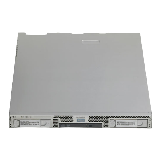
The following sections describe the hardware orientation and features of your Sun Fire X2100 M2 server. 1.3.1 Front and Back Panels shows the front panel of the Sun Fire X2100 M2 server. FIGURE 1-1 Front Panel FIGURE 1-1 Front Panel... - Page 16 Sun Fire X2100 M2 server. FIGURE 1-2 Back Panel FIGURE 1-2 Back Panel TABLE 1-3 Label Connector/Slot Label Connector/Slot Power connector NVIDIA Ethernet connectors (LAN-2 left, LAN-3 right) Broadcom Ethernet connectors (LAN-0 top, Serial management/DB9 RS-232 serial port...
-
Page 17: Internal Components
1.3.2 Internal Components shows the locations of the components inside the Sun Fire X2100 M2 FIGURE 1-3 server. Sun Fire X2100 M2 Server System Components FIGURE 1-3 Sun Fire X2100 M2 Server Internal Components TABLE 1-4 Label Component Label Component... -
Page 18: Powering On And Powering Off The Server
Do not apply main power to the rest of the server until you are ready to install a platform operating system. 2. Continue with initial software setup tasks, as described in Sun Fire X2100 M2 Server Installation Guide. Sun Fire X2100 M2 Server Service Manual • December 2006... -
Page 19: Powering On Main Power Mode
Power/OK LED on the front panel will begin flashing, indicating that the server is in standby power mode. Caution – To completely power off the server, you must disconnect the AC power cords from the back panel of the server. Chapter 1 Sun Fire X2100 M2 Server Overview... -
Page 20: Clearing The Cmos
You can order additional components and replacement parts for the Leo server. Contact your local Sun sales representative for more information. For the most up- to-date component information, see the components list on one of the following web sites: http://sunsolve.sun.com/handbook_pub/Systems/ 1-10 Sun Fire X2100 M2 Server Service Manual • December 2006... -
Page 21: Troubleshooting
C H A P T E R Troubleshooting This chapter contains information on troubleshooting procedures and technical support contacts. The following sections are included in this chapter: Section 2.1, “Troubleshooting Overview” on page 2-2 ■ Section 2.2, “Performing Visual Inspections” on page 2-2 ■... -
Page 22: Troubleshooting Overview
If this does not resolve your problem, then visually inspect the system’s interior hardware for problems, such as a loose card, cable connector, or mounting screw. See Section 2.2.2, “Performing an Internal Visual Inspection” on page 2-3. Sun Fire X2100 M2 Server Service Manual • December 2006... -
Page 23: Performing An External Visual Inspection
2.2.1 Performing an External Visual Inspection 1. Turn off the system and any attached peripherals (if applicable). 2. Verify that all power cables are properly connected to the system, the monitor, and the peripherals, and check their power sources. 3. Inspect connections to any attached devices, including network cables, keyboard, monitor, and mouse, as well as any devices attached to the serial port. -
Page 24: Troubleshooting Procedures
• Reduce the number of external devices connected to a USB hub. connected to a USB • Refer to the documentation that comes with the device. connector does not work. Sun Fire X2100 M2 Server Service Manual • December 2006... - Page 25 10.Stop any processes that look unresponsive or should not be running, by using the kill process_ID command. 11.Check the responsiveness of the Sun Fire X2100 M2 server after each process is stopped. If the above procedure does not work, power cycle the server: 1.
- Page 26 • Move the memory to the other DIMM socket to determine whether the socket is defective. • Make sure that you are using 512 MB, 1 GB, or 2 GB registered DDR2 modules with 3.05 cm max. height. Sun Fire X2100 M2 Server Service Manual • December 2006...
-
Page 27: Performing Diagnostics
C H A P T E R Performing Diagnostics This chapter assists you with using the Diagnostics application on the Sun Fire X2100 M2 Server Tools and Drivers CD that is packaged with your system. Diagnostic output is accessible on systems that are running supported Linux or Solaris operating systems. -
Page 28: Pc-Check Diagnostics Overview
1. Do one of the following, depending on which method you are using to access the Pc-Check diagnostics software: If your server has a DVD drive installed: Insert the Sun Fire X2100 M2 Server Tools ■ and Drivers CD into your DVD drive and reboot the system. -
Page 29: System Information Menu Options
IDE Bus Information Shows the master/slave devices on the primary and secondary IDE controllers. PCMCIA/CardBus Info Not relevant to the Sun Fire X2100 M2 server. Interrupt Vectors Lists and details device interrupt vector information. IRQ Information Shows hardware interrupt assignments. -
Page 30: Advanced Diagnostics Tests Menu Options
Also lists each type of memory in the system, such as system, cache, or video memory. Motherboard Details information about the motherboard, and includes a Motherboard Tests menu to test the motherboard on the system. Sun Fire X2100 M2 Server Service Manual • December 2006... - Page 31 Video Test Options menu that enables you to perform various video tests. Printers Printers are not available for the Sun Fire X2100 M2 server. Firmware - ACPI Details information about Advanced Configurable Power Interface (ACPI), and includes an ACPI Tests menu to test ACPI.
-
Page 32: Testing The Hard Disk
Device Test Settings ■ Enables you to select the test time durations of the devices and the test level. Sun Fire X2100 M2 Server Service Manual • December 2006... -
Page 33: Immediate Burn-In Testing
Number of Retries ■ Enables you to select the number of times to retry testing a device before terminating the test. Maximum Errors ■ Enables you to select the number of errors allowed before terminating the test. Check SMART First ■... - Page 34 Pause on Error Y or N Screen Display Control Panel Control Panel Control Panel or Running Tests POST Card Y or N Beep Codes Y or N Maximum Fails Disabled Disabled 1-9999 Sun Fire X2100 M2 Server Service Manual • December 2006...
-
Page 35: Deferred Burn-In Testing
To load one of the scripts available to test the devices on your system, do the following: ● From the main menu, choose Immediate Burn-in Testing. The top portion of the window lists the options described in , and the TABLE 3-3 bottom portion of the window lists the following Burn-in menu options: Load Burn-in Script... -
Page 36: Create Diagnostic Partition Option
Drivers CD preserves the diagnostic partition. The Create Diagnostic Partition option installs a diagnostic partition on the first bootable disk seen by the Sun Fire X2100 M2 server. The first bootable disk is on the primary/master SATA device. Note – If you are running the Pc-Check Diagnostics software from a PXE server, you do not need to follow the instructions in these procedures for inserting the Tools and Drivers CD into the DVD tray. -
Page 37: Removing Existing Partitions From A Hard Disk
3.6.1 Removing Existing Partitions From a Hard Disk The Create Diagnostic Partition option creates a diagnostic partition on a hard disk only if that hard disk is completely free of any partitions. You need to delete any existing partitions from a hard disk if you plan to use the hard disk to create a diagnostic partition on it. -
Page 38: Adding A Diagnostic Partition To The First Bootable Disk
3. At the Tools and Drivers CD main menu, type 1 to run Hardware Diagnostics. 4. From the main menu, choose Create Diagnostic Partition. If the first bootable disk is clear of partitions, the Sun Microsystems Partitioning ■ Utility window appears. It states: “Your primary hard disk is not partitioned. -
Page 39: Accessing The Diagnostic Partition On A Red Hat Linux System
3. From the Tools and Drivers CD main menu, choose 1 to run Hardware Diagnostics. 4. From the Hardware Diagnostics main menu, choose Immediate Burn-In Testing. 5. Select Load Burn-in Script. 6. Type noinput.tst and press Enter. If you are using a test you have created yourself, you need to enter d:\testname.tst into the Load Burn-in Script field, where testname is the name of the test you have created. - Page 40 8. Type the following to install the diagnostic partition: # ./install.sh 9. Press Enter. The following lines appear if the diagnostic partition is mounted successfully: Mounting Diagnostic Partition Installation Successful 3-14 Sun Fire X2100 M2 Server Service Manual • December 2006...
-
Page 41: Accessing The Diagnostic Partition On The Solaris 10 Operating System
10. Type the following command: # ls /diagpart The contents of the diagnostic partition are listed. 3.6.5 Accessing the Diagnostic Partition on the Solaris 10 Operating System To access the diagnostic partition on a system running the Solaris 10 Operating System: 1. -
Page 42: Accessing The Diagnostic Partition On The Windows Server 2003 Operating System
USB diskette drive to the Sun Fire X2100 M2 server and complete the following procedure. 1. Connect the USB diskette drive to any USB port on the Sun Fire X2100 M2 server. 2. Insert the Tools and Drivers CD into the DVD tray. -
Page 43: Show Results Summary
6. Copy the log file to the diskette. For example, to copy a file named noinput.jrl to the diskette, type: D:> copy d:\noinput.jrl a:\ The journal file is now saved to the diskette in the USB diskette drive. Show Results Summary The summary lists the tests run and shows the results. -
Page 44: Print Results Report
Ensure that your server is connected to a printer, and then enter the required information to print the results. About Pc-Check The About Pc-Check window includes general information about Pc-Check software, including resident and nonresident components, such as mouse devices. 3-18 Sun Fire X2100 M2 Server Service Manual • December 2006... -
Page 45: Exit To Dos
3.10 Exit to DOS You use the Exit to DOS option to exit Pc-Check and return to the DOS prompt. Chapter 3 Performing Diagnostics 3-19... - Page 46 3-20 Sun Fire X2100 M2 Server Service Manual • December 2006...
-
Page 47: Tools And Supplies Needed
If necessary, clean systems by brushing or blowing contaminants from the system or by carefully vacuuming contaminants from the system. Tools and Supplies Needed You need the following tools and supplies for performing Sun Fire X2100 M2 server maintenance procedures. #2 Phillips screwdriver ■... -
Page 48: Installation Precautions
4-2 when handling a system component. 2. Open the server. Section 4.3, “Powering Off the Server and Removing the Cover” on page 4-3 the appropriate procedure for opening the server. Sun Fire X2100 M2 Server Service Manual • December 2006... -
Page 49: Postinstallation Instructions
3. Disconnect the AC power on the back panel of the server (see FIGURE 1-2 4. Label and disconnect all peripheral cables and all telecommunication lines connected to I/O connectors or ports on the back panel of the system. Chapter 4 Maintaining the Sun Fire X2100 M2 Server... - Page 50 7. Pull the cover slightly toward the back of the server and then straight up to remove it. 8. Lift the cover and remove it. Removing the Server Cover FIGURE 4-1 Sun Fire X2100 M2 Server Service Manual • December 2006...
-
Page 51: Locations Of Server Components
PCI-Express riser and cards I/O board Power supply Single fan module Optional hard drive 1 Air duct Dual blower module CPU/heatsink Optional DVD drive DIMM slots (4) Optional hard drive 0 Battery Chapter 4 Maintaining the Sun Fire X2100 M2 Server... -
Page 52: Component Replacement Procedures
The following components should be replaced only by trained field service technicians: CPU - replacement (see Section 4.5.12, “Replacing a CPU and Heatsink” on ■ page 4-38) Motherboard (see Section 4.5.14, “Replacing the Motherboard” on page 4-44) ■ Sun Fire X2100 M2 Server Service Manual • December 2006... -
Page 53: Replacing The I/O Board
3. Remove the screws securing the I/O board to the DVD cage. Removing the I/O Board FIGURE 4-3 4. Pull the I/O board back slightly, then upwards to disengage the board from the guides on top of the HDD cage. Chapter 4 Maintaining the Sun Fire X2100 M2 Server... -
Page 54: Installing The I/O Board
3. Fasten the screws to secure the I/O board to the mounting bracket. 4. Reconnect the cables. 5. Before reinstalling the cover on the server, check the routing of all cables for obstructions. Sun Fire X2100 M2 Server Service Manual • December 2006... -
Page 55: Replacing The Pcie Card And Riser Assembly
2. Placing your fingers on the two green areas on the riser card, pull the assembly upward and out of the chassis. 3. Unlatch the PCIe card and remove the card from the PCIe card riser assembly connector. Chapter 4 Maintaining the Sun Fire X2100 M2 Server... -
Page 56: Installing The Pcie Card And Riser Card Assembly
Installing the PCIe Card and Riser Card Assembly To install the PCIe card and riser card assembly: 1. If necessary, remove the riser card filler panel. Removing the PCIe Riser Card Filler Panels FIGURE 4-7 4-10 Sun Fire X2100 M2 Server Service Manual • December 2006... - Page 57 2. Connect the new PCIe in the riser assembly and fasten the latch to secure it. Installing a PCIe Card FIGURE 4-8 3. Reinstall the riser assembly and card in the connector on the motherboard. Installing the PCIe Card Riser Assembly FIGURE 4-9 Chapter 4 Maintaining the Sun Fire X2100 M2 Server 4-11...
-
Page 58: Replacing A Hard Disk Drive And Carrier
If you are using an IM configuration, start with Step 2. Squeeze the release latch and carefully swing the arm to the left as far as it will Removing a Hard Disk Drive FIGURE 4-10 4-12 Sun Fire X2100 M2 Server Service Manual • December 2006... -
Page 59: Installing An Hdd And Carrier
To install the HDD and carrier: 1. Squeeze the release latch and carefully swing the arm to the left as far as it will Installing the Hard Disk Drive FIGURE 4-11 Chapter 4 Maintaining the Sun Fire X2100 M2 Server 4-13... -
Page 60: Installing A Lsi Pcie Card And Cables
4.5.4 Installing an LSI PCIe Card and Cables This section contains instructions on installing and LSI PCIe card. This card enables the following added functionality for the Sun Fire X2100 M2 server: Standalone SAS hard drive support ■ RAID support using SAS hard drives ■... - Page 61 Make sure to route the blue cable through the dual blower routing clips. ■ SAS Drive Cable Routing FIGURE 4-12 4. Remove the riser assembly from the server. See Section 4.5.2.1, “Removing the Riser Assembly and PCIe Card” on page 4-9. Chapter 4 Maintaining the Sun Fire X2100 M2 Server 4-15...
- Page 62 FIGURE 4-13 7. Install the riser assembly into the server. See Section 4.5.2.2, “Installing the PCIe Card and Riser Card Assembly” on page 4-10. 8. Replace the system cover. 4-16 Sun Fire X2100 M2 Server Service Manual • December 2006...
-
Page 63: Installing The Lsi Card To Support Sata Raid
Disconnect the blue cable from the hard drive backplane and the motherboard ■ connector, then connect the blue cable to the HDD 1 backplane. Make sure to route the blue cable through the dual blower routing clips. ■ Chapter 4 Maintaining the Sun Fire X2100 M2 Server 4-17... - Page 64 5. Connect the SATA cables to the LSI PCIe card connectors. See FIGURE 4-13 Connect the red cable to PHY 0. ■ Connect the blue cable to PHY 1. ■ 4-18 Sun Fire X2100 M2 Server Service Manual • December 2006...
-
Page 65: Removing And Installing An Odd Drive Assembly
The following procedure describes how to replace the optical disk drive (ODD) assembly. If you are not replacing a DVD drive, go straight to Section 4.5.5.2, “Installing the ODD Drive Assembly” on page 4-21. Chapter 4 Maintaining the Sun Fire X2100 M2 Server 4-19... -
Page 66: Removing An Odd Drive Assembly
4. Pull the ODD drive out the front of the chassis. Caution – Move the assembly by grasping it by its sides. Do not push on the DVD-ROM tray. 4-20 Sun Fire X2100 M2 Server Service Manual • December 2006... -
Page 67: Installing The Odd Drive Assembly
2. Position the ODD drive in front of the ODD drive slot on the front panel. 3. Push the ODD drive into the drive slot until the drive clicks into place. Chapter 4 Maintaining the Sun Fire X2100 M2 Server 4-21... -
Page 68: Replacing An Air Duct
1. Power off the system and remove the cover as described in Section 4.3, “Powering Off the Server and Removing the Cover” on page 4-3. 2. Remove the screw fastening the air duct to the chassis divider. 4-22 Sun Fire X2100 M2 Server Service Manual • December 2006... -
Page 69: Installing The Air Duct
1. Position the air duct as shown in , aligning the baffle with the screw FIGURE 4-20 hole and opening in chassis divider. 2. Fasten the screw that attaches the air duct to the chassis divider. Chapter 4 Maintaining the Sun Fire X2100 M2 Server 4-23... -
Page 70: Replacing The Power Supply
2. Disconnect the two power-supply cables from the motherboard and power supply connections to the hard drives. 3. Remove the bracket with the captive screw. 4. Remove the power supply. 4-24 Sun Fire X2100 M2 Server Service Manual • December 2006... -
Page 71: Installing A Power Supply
2. Insert the power supply into the chassis and push it forward so that it is flush with the back panel. 3. Install the power supply bracket on top of the power supply tab and fasten the captive screw. Chapter 4 Maintaining the Sun Fire X2100 M2 Server 4-25... -
Page 72: Replacing The Single Fan
1. Power off the system and remove the cover as described in Off the Server and Removing the Cover” on page 4-3. 2. Pull the fan upward to remove it. 4-26 Sun Fire X2100 M2 Server Service Manual • December 2006... -
Page 73: Installing The Fan
1. Position the fan so that the arrow on top of the fan casing is facing the middle chassis divider. 2. Place the fan in the chassis so that it fits over the small guideposts. Chapter 4 Maintaining the Sun Fire X2100 M2 Server 4-27... -
Page 74: Replacing The Dual Blower Module
5. Check the routing of all cables for obstructions, and then reinstall the cover. 4.5.9 Replacing the Dual Blower Module The following procedures describe how to replace a dual blower module. 4-28 Sun Fire X2100 M2 Server Service Manual • December 2006... -
Page 75: Removing The Dual Blower Module
To install the dual blower module: 1. Position the dual fan module so that it fits over the guideposts and the duct opening fits into the cutouts in the chassis divider. Chapter 4 Maintaining the Sun Fire X2100 M2 Server 4-29... - Page 76 3. Connect the blower connectors to the appropriate connectors on the motherboard. 4. Connect each of the single fan connectors to the corresponding fan harness connector. 5. Check the routing of all cables for obstructions, and then reinstall the cover. 4-30 Sun Fire X2100 M2 Server Service Manual • December 2006...
-
Page 77: Replacing Memory Modules
1. Power off the system and remove the cover as described in Section 4.3, “Powering Off the Server and Removing the Cover” on page 4-3. 2. Locate the DIMM connector in which you will install or replace a memory module. Chapter 4 Maintaining the Sun Fire X2100 M2 Server 4-31... - Page 78 Bank DIMM Slot Locations FIGURE 4-27 3. Remove a DIMM by pressing down on the ejector bars at both ends of the memory module’s socket (see FIGURE 4-28 4-32 Sun Fire X2100 M2 Server Service Manual • December 2006...
-
Page 79: Installing A Dimm
2. Ensure that the DIMM socket’s ejectors are open (rotated outward) to allow the new module to be inserted. 3. Align the DIMM’s edge connector with the alignment key and insert the memory module into the connector. Chapter 4 Maintaining the Sun Fire X2100 M2 Server 4-33... - Page 80 The DIMMs must be inserted evenly, straight down along the DIMM slot until ■ locked into place. The DIMM is seated when you hear a click and the DIMM ejector levers are in the ■ vertical position. 4-34 Sun Fire X2100 M2 Server Service Manual • December 2006...
-
Page 81: Replacing The System Battery
To remove a system battery: 1. Power off the system and remove the cover as described in Section 4.3, “Powering Off the Server and Removing the Cover” on page 4-3. Chapter 4 Maintaining the Sun Fire X2100 M2 Server 4-35... - Page 82 Caution – Do not dispose of the battery with regular waste. Discard used batteries according to the manufacturer’s instructions or contact your local waste-disposal agency for the location of the nearest battery deposit site. 4-36 Sun Fire X2100 M2 Server Service Manual • December 2006...
-
Page 83: Installing The System Battery
Installing the System Battery FIGURE 4-31 Note – Replace the battery only with the identical model. 2. Check the routing of all cables for obstructions. 3. Replace the cover. Chapter 4 Maintaining the Sun Fire X2100 M2 Server 4-37... -
Page 84: Replacing A Cpu And Heatsink
2. Remove the air duct as shown in Section 4.5.6, “Replacing an Air Duct” on page 4-22. 3. Unfasten the four screws securing the heatsink to the board (see FIGURE 4-32 Removing the Heatsink FIGURE 4-32 4-38 Sun Fire X2100 M2 Server Service Manual • December 2006... - Page 85 9. Lift the CPU out of the socket, leaving the release lever in the open position. Note – Ensure that no thermal grease that might be left from the heatsink comes into contact with the CPU socket or underside of the CPU chip. Chapter 4 Maintaining the Sun Fire X2100 M2 Server 4-39...
-
Page 86: Installing A Cpu And Heatsink
Caution – If the CPU is correctly aligned, you should be able to easily insert the CPU into the socket. If you feel more than minimal resistance, stop and recheck the alignment. Forcing a misaligned CPU into the socket can permanently damage the device. 4-40 Sun Fire X2100 M2 Server Service Manual • December 2006... - Page 87 12. Fasten the four screws attaching the heatsink to the motherboard. See FIGURE 4-35 13. Replace the air duct. See Section 4.5.6, “Replacing an Air Duct” on page 4-22. Chapter 4 Maintaining the Sun Fire X2100 M2 Server 4-41...
- Page 88 Installing the Heatsink FIGURE 4-35 14. Reinstall the cover. 4-42 Sun Fire X2100 M2 Server Service Manual • December 2006...
-
Page 89: Replacing Cables
Component Kit Cables Included Cable kit ODD signal, hard drive power, I/O board signal Dual blower kit Fan harness SATA cable kit SATA signal cable Power supply kit Power supply cable Chapter 4 Maintaining the Sun Fire X2100 M2 Server 4-43... -
Page 90: Replacing The Motherboard
J13 - power supply 4.5.14 Replacing the Motherboard The following procedures describe how to remove and install the Sun Fire X2100 M2 server system motherboard. Note – The motherboard is not a CRU and should be replaced only by trained field service technicians. -
Page 91: Removing The Motherboard
5. Remove the five Phillips screws that fasten the motherboard to the chassis. 6. Remove the screws attaching the serial connector to the chassis with a 5 mm nut driver. Removing the Motherboard FIGURE 4-38 Chapter 4 Maintaining the Sun Fire X2100 M2 Server 4-45... -
Page 92: Installing The Motherboard
2. Secure the five Phillips screws that fasten the motherboard to the chassis. Torque screws to 8- to 9-inch pounds. 3. Secure the screws attaching the serial connector to the chassis with a 5 mm nut driver. 4-46 Sun Fire X2100 M2 Server Service Manual • December 2006... - Page 93 Section 4.5.6, “Replacing an Air Duct” on page 4-22 ■ 6. Reconnect all internal system cables. Section 4.5.13, “Replacing Cables” on page 4-43. 7. Replace the system cover. 8. Replace any external cables and power on the server. Chapter 4 Maintaining the Sun Fire X2100 M2 Server 4-47...
- Page 94 4-48 Sun Fire X2100 M2 Server Service Manual • December 2006...
-
Page 95: System Specifications
A P P E N D I X System Specifications This Appendix contains physical, power, and environmental specifications for the Sun Fire X2100 M2 server, as well as pinout information for the serial connector. Physical Specifications lists the physical specifications for the Sun Fire X2100 M2 server... - Page 96 UL maximum (AC input) 6.5 amps ■ Power supply rating (max. DC output) 345 W ■ Environmental Specifications Environmental specifications for the Sun Fire X2100 M2 server are shown in TABLE A-2 Sun Fire X2100 M2 Server Environmental Specifications TABLE A-2 Specification...
- Page 97 Serial Connector Pinout The serial port connector is a DB-9 type connector located on the back panel. Serial Port Connector Pin Configuration FIGURE A-1 Serial Port Connector Pin Assignments TABLE A-3 Signal Description Carrier detect Receive data Transmit data Data terminal ready Ground Data set ready Request to send...
- Page 98 Sun Fire X2100 M2 Server Service Manual • December 2006...
-
Page 99: Using The Tools And Drivers Cd
A P P E N D I X Using the Tools and Drivers CD This chapter contains information on the Sun Fire X2100 M2 Server Tools and Driver CD. It contains information on the following topics: Section B.1, “Tools and Drivers CD Contents” on page B-1 ■... - Page 100 Local Sun Fire X2100 M2 Server DVD Drive To update the BIOS and BMC from the local Sun Fire X2100 M2 server DVD drive: 1. Insert the Tools and Drivers CD into the Sun Fire X2100 M2 server DVD drive.
- Page 101 For example: /remoteflash/1.0/90_3A02 3. Ensure that the OS on the platform is shut down. 4. Log onto the Sun Fire X2100 M2 Embedded LOM CLI and cd into the Tftpupdate: /SP -> cd TftpUpdate 5. Run the following commands from TftpUpdate: /SP/TftpUpdate ->set ServerIPAddress=IP address of tftp server...
- Page 102 6. If an OS is running on the Sun Fire X2100 M2 server that has been updated, reboot the Sun Fire X2100 M2 server in order for the BIOS and BMC updates to take effect. The tftp download will start and you will see the following output.
- Page 103 The Firmware Update screen is displayed. 5. Click Browse and navigate to the location of the flash file. 6. Click Update. The BIOS and BMC firmware on the Sun Fire X2100 M2 server will be updated. Appendix B Using the Tools and Drivers CD...
-
Page 104: Pxe Server
Booting the Tools and Drivers CD from a PXE Server If you have a Sun Fire X2100 M2 server that does not have a DVD drive, you can run the Pc-Check diagnostics and flash the BIOS from a Preboot Execution Environment (PXE) server. - Page 105 Note – If your PXE files are not installed in the /tftpboot/linux-install directory, modify the procedure as necessary. 3. Make a directory for the Sun Fire X2100 M2 Server Tools and Drivers CD contents. # mkdir /tftpboot/linux-install/suppl_leo 4. Insert the Sun Fire X2100 M2 Server Tools and Drivers CD into the PXE server, and copy the boot.img file located in the root directory of the CD to the new...
- Page 106 8. Copy the memdisk kernel to the new Sun Fire X2100 M2 Server Tools and Drivers Directory created in Step For example: cp /syslinux-3.09/memdisk/memdisk /tftpboot/linux-install/suppl_ 9. Edit the Boot Message Screen as follows. a. Open the boot.msg file in a text editor.
- Page 107 Accessing the Tools and Drivers CD From the Target Sun Fire X2100 M2 Server You will need the following to run diagnostics on a target Sun Fire X2100 M2 server: PXE server configured as shown in Section B.3.1, “Setting up the Tools and ■...
- Page 108 One of the broadcom NICs is shared with the SP. Including two broadcom NICs ■ as a team will disrupt the SP management feature. For more information, refer to the users guide included with the broadcom software. B-10 Sun Fire X2100 M2 Server Service Manual • December 2006...
-
Page 109: Installing The Server Into A Rack With Optional Slide Rails
A P P E N D I X Installing the Server Into a Rack With Optional Slide Rails Perform the procedures in this chapter to install your server into a four-post rack using the orderable slide rail and cable management arm options. These slide rails are compatible with a wide range of equipment racks that meet the following standards: Four-post structure (mounting at both front and rear). - Page 110 , and simultaneously withdraw the mounting FIGURE C-1 bracket from the slide-rail assembly. 5. Repeat for the remaining slide-rail assembly. Mounting bracket release button Slide-rail lock Disassembling the Slide Rail Before Installation FIGURE C-1 Sun Fire X2100 M2 Server Service Manual • December 2006...
-
Page 111: The Server
Installing the Mounting Brackets Onto the Server Use this procedure to install the mounting brackets onto the sides of the server. 1. Position a mounting bracket against the chassis so that the slide-rail lock is at the server front, and the three keyed openings on the mounting bracket are aligned with the three locating pins on the side of the chassis. - Page 112 Slide-rail assembly Rack post Slide-rail assembly bracket on outside of rack post Slide-Rail Assembly Mounting to Rack Post FIGURE C-3 Sun Fire X2100 M2 Server Service Manual • December 2006...
- Page 113 3. Repeat Step 1 Step 2 for the remaining slide-rail assembly. 4. From the front of the rack, set the proper width of the rails with the spacer. (See FIGURE C-4 Rail-width spacer Setting the Rail Width FIGURE C-4 5. Tighten the screws on the brackets. 6.
- Page 114 Caution – Always load equipment into a rack from the bottom up so that it will not become top-heavy and tip over. Deploy your rack’s anti-tilt bar to prevent the rack from tipping during equipment installation. Sun Fire X2100 M2 Server Service Manual • December 2006...
- Page 115 1. Push the slide rails into the slide-rail assemblies in the rack as far as possible. 2. Raise the server so that the rear ends of the mounting brackets are aligned with the slide-rail assemblies that are mounted in the equipment rack. (See FIGURE C-6 3.
- Page 116 The CMA rail extension might be taped to the CMA assembly. Left slide-rail CMA rail extension Inserting the CMA Rail Extension Into the Back of the Left Slide Rail FIGURE C-7 Sun Fire X2100 M2 Server Service Manual • December 2006...
- Page 117 4. Verify that the CMA rail extension engages the slide rail, as shown in FIGURE C-8 CMA rail extension Left slide rail Detail of CMA Rail Extension Inserted Into the Left Slide Rail FIGURE C-8 Note – Support the CMA in the remaining installation steps. Do not allow the assembly to hang by its own weight until it is secured by all three of the attachment points.
- Page 118 (See FIGURE C-9 Right slide rail CMA mounting bracket Inserting the CMA Mounting Bracket Into the Back of the Right Slide Rail FIGURE C-9 C-10 Sun Fire X2100 M2 Server Service Manual • December 2006...
- Page 119 6. Insert the right CMA slide-rail connector into the right slide-rail assembly until the connector locks into place with an audible click. (See FIGURE C-10 Right slide- rail assembly CMA slide-rail connector Inserting CMA Slide-Rail Connector Into Back of Right Slide-Rail Assembly FIGURE C-10 Appendix C Installing the Server Into a Rack With Optional Slide Rails C-11...
- Page 120 (See FIGURE C-11 CMA arm connector CMA extension (on left slide rail) Connecting the CMA Arm to Rail Extension Connector FIGURE C-11 C-12 Sun Fire X2100 M2 Server Service Manual • December 2006...
- Page 121 8. Position the cable hangers in the appropriate mounting holes in the CMA and snap them into place. (See FIGURE C-12 For best results, place three hangers, evenly spaced, on the rear-facing side of the CMA and three on the side facing the server. CMA arm CMA cable hanger Installing CMA Cable Hangers...
- Page 122 . Simultaneously push or pull both of FIGURE C-6 the slide-rail release buttons and push the server completely into the rack until both slide-rail locks engage. 5. Adjust the cable hangers and CMA as required. C-14 Sun Fire X2100 M2 Server Service Manual • December 2006...
- Page 123 Appendix C Installing the Server Into a Rack With Optional Slide Rails C-15...
- Page 124 C-16 Sun Fire X2100 M2 Server Service Manual • December 2006...
- Page 125 Index orderable, 1-10 replacement procedures, 4-6 air duct cover removal, 4-3 location, 1-7, 4-5 replacing, 4-22 location, 1-7, 4-5 altitude specifications, A-2 replacing, 4-38 specifications, 1-2 customer orderable components, 1-10 battery customer replaceable unit replacement location, 1-7, 4-5 procedures, 4-6 replacing, 4-35 BIOS fimware updating with Embedded LOM WebGUI, B-4...
- Page 126 4-2 physical system specifications, A-1 preinstallation instructions, 4-2 power button, 1-5 installing to a rack, C-1 power button LED, troubleshooting, 2-5 internal components, 1-7, 4-5 power connector, 1-6 Index-2 Sun Fire X2100 M2 Server Service Manual • December 2006...
- Page 127 power LED, 1-5, 1-6 booting from a PXE server, B-6 Broadcom NetXtreme software, B-9 power problems software overview, 1-4 troubleshooting, 2-4 tools for maintenance procedures, 4-1 power supply location, 1-7, 4-5 troubleshooting replacing, 4-24 CD or DVD media, 2-5 CD or DVD problems, 2-4 power system specifications, A-2 external device, 2-6 powering off for service, 4-3...
- Page 128 Index-4 Sun Fire X2100 M2 Server Service Manual • December 2006...
Need help?
Do you have a question about the Sun Fire X2100 M2 and is the answer not in the manual?
Questions and answers